ControlNet Coax Cable System Planning and Installation_RN
同轴线质量控制计划

同轴线质量控制计划英文回答:Coaxial cable is widely used in various industries for transmitting signals and data. As a quality control engineer, it is crucial to have a well-defined andeffective quality control plan for coaxial cable production. In this plan, I will outline the key steps and methods to ensure the quality of coaxial cables.Firstly, it is important to establish clear quality standards and specifications for the coaxial cables. These standards should cover various aspects such as the dimensions, electrical properties, and mechanical strengthof the cables. For example, the cable should have aspecific impedance value, a certain level of shielding effectiveness, and meet the required tensile strength.Secondly, a comprehensive inspection process should be implemented throughout the production line. This includesboth visual inspection and testing of the cables. Visual inspection can identify any visible defects such as physical damages or improper connectors. Testing can be done using specialized equipment to measure the electrical properties of the cables, such as impedance, capacitance, and attenuation. Any cables that fail to meet the specified standards should be rejected and not proceed to the next stage of production.Additionally, it is crucial to conduct regular sampling and testing of the finished coaxial cables. This can be done by randomly selecting a certain number of cables from each batch and subjecting them to thorough testing. This ensures that the quality of the cables is consistent and meets the required standards. For example, I can randomly select 10 cables from a batch of 100 and test them for various parameters. If all 10 cables pass the tests, it indicates that the batch meets the quality standards.Furthermore, it is important to have a feedback system in place to address any quality issues that arise during production. This includes collecting data on any defects orfailures encountered and analyzing the root causes. By identifying the root causes, appropriate corrective actions can be taken to prevent similar issues from occurring in the future. For example, if there is a recurring issue of poor shielding effectiveness, I can investigate the manufacturing process and make necessary adjustments to improve the shielding quality.In conclusion, a robust quality control plan for coaxial cable production is essential to ensure thedelivery of high-quality cables to customers. By establishing clear standards, implementing thorough inspections and testing, conducting regular sampling, and addressing any quality issues, we can maintain the quality and reliability of coaxial cables.中文回答:同轴电缆被广泛应用于各个行业,用于传输信号和数据。
ControlNet培训教程
ControlNet培训教程ControlNet是一种高速的、可靠的工业通信协议,广泛应用于工业自动化领域。
ControlNet网络可以连接多种工业设备,包括控制器、传感器、执行器等,实现设备之间高速、可靠的数据交换和控制指令传输。
ControlNet培训教程是指教授ControlNet网络基础知识、原理、配置和调试等方面的培训课程。
下面将详细介绍ControlNet培训教程的主要内容。
一、ControlNet网络基础知识ControlNet培训教程的第一部分是ControlNet网络基础知识,包括ControlNet网络的概念、基本组成、特点和应用场景等。
学习者需要了解ControlNet网络的工作原理、网络拓扑、通信协议和数据传输速率等基本概念。
此外,还需要了解ControlNet网络的优点和局限性,以及与其他工业通信协议的对比等方面的知识。
二、ControlNet网络硬件配置ControlNet培训教程的第二部分是ControlNet网络硬件配置,包括ControlNet网络组成设备的选型、安装和连接等方面的知识。
学习者需要了解不同类型的ControlNet设备,例如控制器、I/O模块、驱动器和传感器等的功能和特点,以及如何正确安装和连接这些设备。
此外,还需要了解ControlNet网络的电源、地线、终端电阻和信号放大器等方面的知识。
三、ControlNet网络软件配置ControlNet培训教程的第三部分是ControlNet网络软件配置,包括ControlNet网络软件的安装、配置和调试等方面的知识。
学习者需要了解ControlNet网络软件的不同组件、驱动程序和插件等,以及如何正确配置和使用这些软件。
此外,还需要了解如何使用ControlNet网络工具进行网络诊断、故障排除和性能优化等方面的知识。
四、ControlNet网络应用实例ControlNet培训教程的第四部分是ControlNet网络应用实例,包括实际工业自动化场景下的ControlNet网络设计和应用案例。
ControlNet现场总线

• 维护时段:所有节点停止发送数据 • 协调节点:MAC ID最小 • 发送维护报文(协调帧)完成NUT定时器 的同步,发布重要网络参数 • 协调节点发送重同步协调帧→重启NUT→ 节点接收协调帧→比较→不一致→节点失 效 • 在两个连续的NUT中未收到协调帧→最低 MAC ID节点承担协调节点→第三个NUT维 护时段发送协调帧→遇到比其低的MAC ID 节点→停止协调角色 • 协调帧在每个NUT都要发送,以调整参数, 并为新加入的节点提供参数。
• -中继器:工作在物理层的设备,其功能 是双向接收、处理并重发物理信号。 • 用途:1、用于网络拓展 • 2、用于传输介质或拓扑结构的切换 • 分类: • 普通中继器:两个网络接口 • 环中继器:3个网络接口,支持介质冗余
MAC协议
• 数据链路层协议以NUT的固定而重复的时间周期 为基准。 • 功能:负责整个网络仲裁,确定信息发送的优先 权。 • 隐性令牌传递:并非真正的令牌 • 规则:一个节点一个MAC地址(惟一) • 每个节点监视收到的数据帧的源节点地址→结束 →隐性令牌寄存器的值置为收到的源MAC地址+ 1→等于某节点MAC地址→该节点发送数据 • 避免冲突:所有节点的隐性令牌寄存器值相同, 节点本身的MAC地址不同 • 隐性令牌传递逻辑是由CTDMA算法控制的。
• 网络刷新时间(NUT)分配 • NUT分为3个部分:预定时段、非预定时段和网络 维护时段。 • 预定时段:传送对时间有苛刻要求的控制信息。 • MAC ID:0~SMAX • 节点访问媒体的机会是相同的,有且仅有一次发 送预定数据的机会,保证网络在预定时段内发送 的数据是可预测的、确定的。 • 不同的数据不同的发送速率。ControlNet支持8种 不同的速率,是NUT的二进制倍数。 • 用户选择请求数据包间隔,网络组态工具设置实 际数据包间隔。
controlnet原理

controlnet原理ControlNet是一种用于工业自动化的高速、可靠的通信网络。
它被广泛应用于汽车制造、食品加工、石油化工等领域。
ControlNet的原理基于CAN(Controller Area Network)总线技术,但是在速度、可靠性和数据传输距离上有所提升。
ControlNet的拓扑结构包括主站、从站和媒体。
主站负责控制整个网络,从站则是执行命令和传输数据的设备。
媒体是网络中传输数据的介质,通常采用同轴电缆或光纤。
ControlNet使用了一种称为CIP(Common Industrial Protocol)的通信协议。
CIP定义了数据传输格式和命令协议,确保了不同设备之间的互操作性。
CIP还支持多种安全机制,例如身份验证和加密。
ControlNet具有以下特点:1. 高速:ControlNet最高可以达到5Mbps的数据传输速度,比CAN总线快得多。
2. 可靠性高:ControlNet采用了分布式控制结构,即每个节点都可以独立运行,在某个节点故障时不会影响整个系统运行。
3. 数据传输距离远:ControlNet可以支持长达1000米以上的数据传输距离,这使得它适用于大型工厂和生产线。
4. 支持多种拓扑结构:ControlNet支持星形、环形、总线等多种拓扑结构,可以根据实际应用需求进行选择。
ControlNet的数据传输过程如下:1. 主站向从站发送命令或请求数据。
2. 从站接收到命令或请求后,执行相应的操作并将结果返回给主站。
3. 主站收到从站返回的数据后,进行相应的处理并向其他节点广播结果。
4. 其他节点收到广播后,更新自己的状态并继续执行任务。
ControlNet还可以与其他网络进行互联,例如以太网和无线网络。
这样可以实现不同设备之间的数据交换和协同控制。
同时,ControlNet 也支持远程监控和故障诊断功能,可以帮助用户快速定位问题并采取相应措施。
总之,ControlNet是一种高速、可靠、灵活的工业自动化通信网络。
ControlNet培训教程

ControlNet培训教程ControlNet培训教程一、介绍ControlNet是一种用于工业自动化控制系统的网络通信协议,它确保了高性能、高可靠性和实时性。
它主要用于传输控制系统中的实时数据和命令,并提供了高带宽和可靠的通信连接。
ControlNet培训教程旨在帮助用户快速了解ControlNet的基本原理和操作,从而更好地理解和应用ControlNet网络。
二、基本概念1. ControlNet网络拓扑结构:ControlNet 网络由主站(scanner)和从站(adapter)组成。
主站负责发送命令和控制信息,从站负责接收和执行命令。
ControlNet网络可以支持多个主站和从站,形成多站式拓扑结构,也可以支持多个主站共享一个从站的方式,形成共享式拓扑结构。
2. ControlNet网络传输媒介:ControlNet可以使用双绞线或光纤作为物理传输媒介。
双绞线适用于短距离通信,光纤适用于长距离通信。
双绞线的传输速率为5Mbps,光纤的传输速率可高达100Mbps。
3. ControlNet网络数据通信:ControlNet使用了一种被称为CIP(ControlNet Industrial Protocol)的通信协议,它定义了主站和从站之间数据的传输格式和协议规则。
CIP采用了面向连接的通信方式,并使用轮询方式实现数据的传输。
主站周期性地轮询每个从站,并向其发送命令和控制信息。
三、ControlNet网络配置1. ControlNet网络硬件配置:ControlNet网络的硬件配置包括主站、从站和网络传输媒介等。
主站负责控制整个网络的操作和管理,从站负责执行主站发送的命令和控制信息。
主站和从站之间的连接通过网络传输媒介实现。
2. ControlNet网络地址分配:ControlNet网络中的每个从站都需要有一个唯一的节点地址,以便主站能够识别和与之通信。
通常,节点地址通过从站的硬件开关或软件设置来配置。
controlnet 参数

controlnet 参数
ControlNet是一种使用在工业自动化应用中的网络。
它采用了一种双绞线的硬件接口,可以提供高速、可靠的数据传输。
以下是ControlNet的一些参数:
1. 传输速度:ControlNet可以支持最高5 Mbps的数据传输速度,这使得它适用于需要快速、实时的数据传输的应用。
2. 最大网络长度:ControlNet支持最大网络长度为1000米。
这样的长度允许在大型工厂环境中连接多个设备。
3. 最大节点数量:ControlNet网络可以支持最多99个节点。
每个节点可以是PLC、HMI、IO模块或其他控制设备。
4. 网络拓扑:ControlNet网络支持多种拓扑结构,包括线性、星形和树状。
这使得它可以适应不同的工厂布局和设备连接需求。
5. 通讯协议:ControlNet使用了CIP(Common Industrial Protocol)作为其通讯协议。
CIP是一种开放、标准化的通讯协议,可以实现设备之间的互操作性和数据交换。
6. 安全功能:ControlNet提供了诸如数据加密、数据完整性验证和身份认证等安全功能,以确保网络通讯的安全性。
7. 故障恢复:ControlNet拥有自动故障检测和恢复功能,当网络中的某个节点失效时,它可以自动重新路由数据,以保证数
据传输的连续性。
需要注意的是,ControlNet是一种专有的网络技术,它是罗克韦尔自动化(Rockwell Automation)开发和推广的。
在选择使用ControlNet网络时,需要确保所使用的设备和系统支持该技术。
controlnet 原理
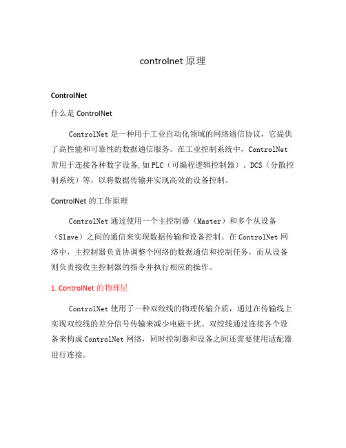
controlnet 原理ControlNet什么是ControlNetControlNet是一种用于工业自动化领域的网络通信协议,它提供了高性能和可靠性的数据通信服务。
在工业控制系统中,ControlNet 常用于连接各种数字设备,如PLC(可编程逻辑控制器)、DCS(分散控制系统)等,以将数据传输并实现高效的设备控制。
ControlNet的工作原理ControlNet通过使用一个主控制器(Master)和多个从设备(Slave)之间的通信来实现数据传输和设备控制。
在ControlNet网络中,主控制器负责协调整个网络的数据通信和控制任务,而从设备则负责接收主控制器的指令并执行相应的操作。
1. ControlNet的物理层ControlNet使用了一种双绞线的物理传输介质,通过在传输线上实现双绞线的差分信号传输来减少电磁干扰。
双绞线通过连接各个设备来构成ControlNet网络,同时控制器和设备之间还需要使用适配器进行连接。
2. ControlNet的数据链路层ControlNet的数据链路层采用了开放式主从结构,主控制器使用Token来控制网络中的数据传输。
主控制器通过向下一个设备传递Token的方式来控制数据传输的顺序,从而保证数据传输的高效性和可靠性。
3. ControlNet的网络层ControlNet的网络层负责处理数据的路由和转发,保障数据的准确传输。
网络层使用了一种基于CIP(Common Industrial Protocol)的协议栈,该协议栈提供了各种功能,如地址解析、错误检测和纠错等。
ControlNet的优势和应用1. 优势•高性能和可靠性:ControlNet具有高速传输和低延迟的特点,可以满足工业控制系统对实时性要求较高的场景。
•强大的网络管理能力:ControlNet支持多主控制器,可以灵活地管理和控制网络中的各个设备。
•易于维护和扩展:ControlNet提供了诊断和监控功能,可以方便地进行网络故障排除和设备管理。
ControlNet概述及其介质

如果系统在这个区域 存在信号衰减,并不需 要中继器
单独网段 的图表
2
16
32
48
10
(Confidential – For Internal Use Only) Copyright © 2007 Rockwell Automation, Inc. All rights reserved.
设备数量
同轴电缆干线网段技术规范
备用分接器
虚拟负载终端 (1786-TCAP)
可以安装一个BNC连接器来代替分 接器 。这能够减少进入系统的噪声 ,但是当增加设备时,不得不破坏 网络,然后安装分接器 。
9
(Confidential – For Internal Use Only) Copyright © 2007 Rockwell Automation, Inc. All rights reserved.
电缆长度
如果系统在这个区域内 存在信号衰减,并不需 要中继器
单独网段 的图表
2
16
32
48
11
设备数量
(Confidential – For Internal Use Only) Copyright © 2007 Rockwell Automation, Inc. All rights reserved.
网络连接
网络上的所有固定节点都应该使用分接器连接 。也可以使用网络端口、或NAP找到临近设备 分接器的NBC连接器,暂时连接到网络。
Prog
BATT
NAP是耳机塞孔样式的连接器,允许使用现有 的设备连接到网络。NAP与使用分接器连接一 样,提供网络的全部访问权,而不仅限于连接 的设备。
R E M
PROC
- 1、下载文档前请自行甄别文档内容的完整性,平台不提供额外的编辑、内容补充、找答案等附加服务。
- 2、"仅部分预览"的文档,不可在线预览部分如存在完整性等问题,可反馈申请退款(可完整预览的文档不适用该条件!)。
- 3、如文档侵犯您的权益,请联系客服反馈,我们会尽快为您处理(人工客服工作时间:9:00-18:30)。
1786-6.2.1-RN1 - June 1999Release NoteControlNet Coax Media Planning and Installation ManualUsing the Flare Tool Use this release note with the ControlNet Coax Media Planning andInstallation Manual, publication 1786-6.2.1.The flare tool replaces the calibration tool in the ControlNet Coax Toolkit, catalog number 1786-CTK. The flare tool is a combination calibration tool and cable shield expander.1786-6.2.1-RN1 - June 19992ControlNet Coax Media Planning and Installation Manual Release NoteCollect Your Tools To install the cable connectors, we recommend that you use the tools in theControlNet Coax Toolkit, catalog number 1786-CTK.Important:This page replaces page 3-9 in the ControlNet Coax MediaPlanning and Installation Manual, 1786-6.2.1.41902!ATTENTION: Be certain to perform the calibrationprocedure the first time you use the tool and every timeyou change the blade for both memory cartridges. Referto Appendix B of the ControlNet Coax Media Planningand Installation Manual, publication 1786-6.2.1, for theproper calibration procedure. Due to slight differencesbetween COAX cables, calibration should be performedwhen changing:–part numbers–from one cable manufacturer to another1786-6.2.1-RN1 - June 1999ControlNet Coax Media Planning and Installation Manual Release Note 3Strip the Cable Important:Pages 3 through 7 replace pages 3-10 through 3-13 in theControlNet Coax Media Planning and Installation Manual,publication 1786-6.2.1.When cutting cable sections, make them long enough to route from one tap to the next with sufficient length so that the bend radius is not less than:•76.2mm (3”) for wiring external to enclosures•38.1mm (1.5”) for wiring inside enclosures1.Verify that you have the proper memory blade holder installed for the type of cable you are using (PVC-CL2 or FEP-CL2P). If you need to change the memory blade holder, see Appendix B of the ControlNet Coax Media Planning and Installation Manual, publication 1786-6.2.1.2.Straighten out the end of the cable.3.Insert the cable into the cable strip tool’s cutting chamber so that extra cable, approximately 25.4mm (1”), extends beyond the edge of the tool.!ATTENTION: Be certain to perform the calibrationprocedure the first time you use the tool and every timeyou change the blade or both memory cartridges. Referto Appendix B of the ControlNet Coax Media Planningand Installation Manual, publication 1786-6.2.1, for theproper calibration procedure.1786-6.2.1-RN1 - June 19994ControlNet Coax Media Planning and Installation Manual Release Note4.Lock the cable into place by moving the chamber-gauge ring forward until it meets the cable with slight resistance.5.Holding the cable in one hand, place the index finger of your other hand inside the chamber-gauge ring and turn the strip tool 360° around the cable. Turn four or five full rotations until the strip tool glides easily around the cable. Important:On your last repetition of steps 4 and 5, apply sufficient pressure on the chamber gauge ring to make sure the ring has reached the last stage. The chamber gauge read ‘stop’ for thelast repetition.20073notch, the strip tool makes a deeper cut into the cable.200741786-6.2.1-RN1 - June 1999ControlNet Coax Media Planning and Installation Manual Release Note 56.After you have moved the chamber gauge ring to the last position and turned the strip tool the final time:a.Move the chamber-gauge ring backward to release the strip tool andremove it from the cable.b.Slip the crimp ferrule onto the cable. Push it back to the sheath areaof the cable to keep it out of the way for the moment.c.Strip away the appropriate portion of the cable without using thestrip tool.d.Clean the remaining cable parts from the strip chamber after eachuse.This procedure should appropriately strip the cable, exposing these layers of the cable:Important:If you do not see the three distinct layers of cable or if the outerbraid has been scored or cut, snip off the exposed end with thewire cutters and repeat the entire cable-stripping process. It isvery important that the outer braid be intact before crimpingconnector.all 4 shield layerswhite foam electriccenterconductor4.0 mm20076a1786-6.2.1-RN1 - June 19996ControlNet Coax Media Planning and Installation Manual Release NoteIf stripping problems persist, the strip tool may need adjustment. See Appendix B of the ControlNet Coax Media Planning and InstallationManual, publication 1786-6.2.1, for instructions on how to adjust the strip tool.7.If you are using plenum FEP cable, cut off an additional 3.1mm(approximately 1/8”) of the outer sheath with the knife from the toolkit.8.Be certain that the center conductor is 4.0 mm. Use the imprint guide on the back of the ControlNet tap or the calibration tool to verify this. If you are using:Go to step:FEP cable 7PVC cable 84.0 mm20076atool to verify proper measurements for FEP cable.The center conductor should be 4.0 mm exactly. If thecenter conductor is too long, cut off the excess with thewire cutter from the cable kit. If it is too short, repeat theentire cable stripping process.41952ControlNet Coax Media Planning and Installation Manual Release Note7!ATTENTION: Check for any braid stranding that may not have been cut at the proper length. If one strand comes in contact with the center conductor, it could short out the cable. If you find any such strands, cut them to the correct length.!ATTENTION: Check the outer braid of cable for cut or scored braid wire after you strip the cable. If the braid is damaged, cut off the end and strip the cable again. Youmay need to adjust the appropriate striper blade bybacking the set screw out 1/8 of a turn. Do not crimp theBNC to a damaged braid. This type of mistake accountsfor most of the connectivity problems that can occur. Precise, clean connections will reduce network errors.1786-6.2.1-RN1 - June 19991786-6.2.1-RN1 - June 19998ControlNet Coax Media Planning and Installation Manual Release NoteAttach the Connectorsto the CableImportant:Pages 8 through 10 replace pages 3-15 through 3-16 in the ControlNet Coax Media Planning and Installation Manual, publication 1786-6.2.1.1.Push the flare tool onto the cable and with a slight twisting motion (with sufficient inward pressure ) to expand the braid.2.Place the center pin over the center conductor. Important:Be certain that the center pin slips onto the center conductor completely. The back shoulder of the center pin should be up against the white insulation. If it is not, recheck the length of the center conductor.ControlNet Coax Media Planning and Installation Manual Release Note9 3.With the center pin in place, use the crimp tool to crimp the pin intoplace.4.Slide the ControlNet connector onto the cable.braid and tape shields1786-6.2.1-RN1 - June 19991786-6.2.1-RN1 - June 199910ControlNet Coax Media Planning and Installation Manual Release Note 5.Slide the crimp ferrule over the three outer shields and connector base until it meets the shoulder on the connector. ing the crimp tool, crimp the ferrule. Position the crimp tool on the ferrule as close as possible to the connector base and ferrule meeting line. Press the tool tightly around the ferrule until the crimp tool allows release. Important:Many network problems are due to improperly installed connectors. You should have tight-fitting connectors on the ends of all your cables. Pull the connector to verify that it is attached. If it is loose or comes off, snip off the connector and install a new one. The connector should withstand a minimum75lbs pull force if properly installed.20077e crimp ferrule The larger hexagonal crimping notch is for crimping the ferrule which holds the connector to the cable.1786-6.2.1-RN1 - June 1999ControlNet Coax Media Planning and Installation Manual Release Note 11Adjust the Cable Strip Tool Calibrate The Cutting BladesImportant:Pages 11 and 12 replace pages B-1 and B-2 in the ControlNetCoax Media Planning and Installation Manual, publication1786-6.2.1.Use the following procedure to calibrate your cable strip tool to cut FEP orPVC cable.1.Turn the three screws outward to back the blades out. This prevents thecalibration tool from bottoming out.2.Place the calibration tool into the cable strip tool with the narrow endinstalled and facing forward for FEP cable (use the wider end for PVC).3.Tighten the chamber gauge ring so that the calibration tool is locked inplace. Close all the way to the chamber gauge stop.Important:When aligned properly, the grooves of the calibration toolshould align with the blades.4.Adjust the screws of the memory clip so that the blades just touch thecalibration tool.5.Retract the handle of the cable strip tool.6.Remove the calibration tool from the cable strip tool.!ATTENTION: Do not over-tighten the screws of thecable strip tool. The blades should not bend, shift, orpenetrate the calibration tool.Publication 1786-6.2.1-RN1 - June 1999PN 957208-01Copyright 1999 of Rockwell International Corporation. Printed in the U.S.A.12ControlNet Coax Media Planning and Installation Manual Release NoteWhen finished, the blade should make a cut of the following dimensions inyour cable.Important:The first and second cut adjustments need to be precise.Adjustments as small as 1/12 to 1/8 of a turn can make thedifference between a perfect and an imperfect cut.The first cut should cut theouter sheath without cuttingthe outer wire braid. If thebraid is frayed, scored, or cutby the blade, adjust the bladeoutward slightly to eliminatethe fraying.The second cut should cut the sheath, three outer shields, and possibly the inner tape shield. The insulation can be scored slightly, but should not have a deep cut.The third cut should cut all layers of the cable down to the center conductor. This cut should not score the center conductor. If the blade leaves a mark on the conductor, adjust the blade slightly so to eliminate markingthe conductor.30030-m!ATTENTION: Check the outer braid of cable for cut orscored braid wire after stripping the cable. If the braid isdamaged, strip the cable again. If needed, adjust theappropriate striper blade by backing the set screw out 1/8of a turn. Do not crimp the BNC to a damaged braid.This type of mistake accounts for most of theconnectivity problems that occur. Precise, cleanconnections will reduce network errors.。