CJTKC说明书-G1
冠景电动工具产品说明书

OWNER’S MANUAL & OPERATING INSTRUCTIONS12039 Smith Ave.Santa Fe Springs CA 90670USA / 1-877-338-0999SAVE THESE INSTRUCTIONS Important Safety Instructions are included in this manual.MADE IN CHINAREV 14001-20180821ATV/UTV Winch Kit4000 lb.WARNING: Cancer and Reproductive Harm – *We are always working to improve our products. Therefore, the enclosed product may differ slightly from the image on the cover.ENGLISH14001 INTRODUCTIONIntroductionCongratulations on your purchase of a Champion Power Equipment winch. CPE designs and builds winches to strict specifications. With proper use and maintenance, this winch will bring years of satisfying service.This BookletEvery effort has been made to ensure the accuracy and completeness of the information in this manual. We reserve the right to change, alter and/or improve the product and this document at any time without prior notice. AccessoriesChampion Power Equipment manufactures and sells accessories designed to help you get the most from your purchase. To find out more about our covers, tree savers, hooks, fairleads, etc., please visit our web site at:Record the model and serial numbers as well as date and place of purchase for future reference. Have this information available when ordering parts and when making technical or warranty inquiries.114001ENGLISHThis manual uses the following symbols to help differentiate between different kinds of information. The safety symbol is used with a key word to alert you to potential hazards in operating and owning power equipment.Follow all safety messages to avoid or reduce the risk of serious injury or death.MANUAL CONVENTIONS23ENGLISH 14001SAFETY RULES14001ENGLISHSAFETY RULES4ENGLISH14001Read this owner’s manual before operating your winch. Familiarize yourself with the location and function of the controls and features. Save this manual for future reference.(1) Motor – 1.4 HP 12V DC motor providespower to the planetary gear mechanism. (2) Braking System – Braking action isautomatically applied to the winch drumwhen the winch motor is stopped andthere is a load on the wire rope.(3) Winch Drum – The winch drum is thecylinder on which the wire rope is stored.It can feed or wind the rope depending onthe remote winch switch.(4) Planetary Gear System – The reductiongears convert the winch motor power intoextreme pulling forces. This system allowshigh torque while maintaining compactsize and light weight.(5) Free spooling Clutch – The clutch allowsthe operator to manually disengage “Out”the spooling drum from the gear train, freespool. Engaging the clutch “In” locks thewinch into the gear system.(6) Mount Assembly – Flatbed mountingchannel. (7) Roller Fairlead – When using the winch atan angle the roller fairlead acts to guidethe wire rope onto the drum and minimizesdamage to the wire rope from abrasion onthe winch mount or bumper.(8) Wire Rope – 7/32 in. x 49 ft. galvanizedaircraft cable designed specifically for loadcapacity of 4000 lb. (1814 kg).(9) Winch Connection Cables – Used toconnect the contactor to the winch motor. (10) Battery Connection Cables – Used toconnect the battery to the contactor. (11) Clevis Hook – Provides a means forconnecting the looped ends of cables toan anchor.(12) Strap – Used to assist cable feed.(13) Contactor/solenoid – Power from thevehicle battery flows through the weathersealed contactor/solenoid switch beforebeing directed to the winch motor.(14) Rocker Switch – Rocker switch withhandlebar mount for powering the rope inor out of your winch drum.CONTROLS AND FEATURES5614001 ENGLISHASSEMBLYAssembling the WinchThis CPE 4000 lb. (1814 kg) winch is designed with a bolt pattern that is standard in this class of winch. Many winch mounting kits are available that utilize this bolt pattern for the most popular UTVs and ATVs. If you cannot find a kit locally, contact CPE and we will provide you with the name of a dealer.1. Insert M10x20 bolts through the mountingchannel holes and attach the roller fairlead to the mounting channel with the M10 lockwashers and M10 nuts provided.2. Turn the winch upside down. Place themounting channel on the winch, making sure the winch is centered in the middle of it.3. Thread the M8x25 bolts through the M8 flatand lockers washers, and then thread through the mounting channel. Tighten the bolts. DO NOT over tighten.4. Turn winch right side up. Disengage theclutch by moving the Cam Ring to the “Out” position. Release the wire rope and pull through the roller fairlead.5. Attach the clevis hook to the cable, and thenhand strap to the clevis hook.Assembling the Winch Cont’d.Contactor/solenoid LocationFind a location for the contactor/solenoid. It is recommended that the contactor/solenoid be mounted close to the battery in a clean, drylocation. Make sure the location chosen allows for sufficient clearance from all metal components. Drill mounting holes if required. Once a location is found, DO NOT install the unit until all wiring is completed (see wiring section).Installing the Rocker Switch1. Decide which handlebar the rocker switch willbe mounted on. (The rocker switch is usually installed on the left handlebar).2. Use a piece of electrical tape (not provided)around the handlebar to help prevent rotation of the mount.3. Tighten the rocker switch in place. DO NOTover tighten or tighten/clamp over any hoses or cables.4. Once the rocker switch is mounted, the wirescan be routed back to where the contactor/solenoid is located.5. Make sure the handlebars have full range ofmotion and then secure the rocker switch’scable with the supplied cable ties.7ENGLISH 14001ASSEMBLYLeads default position.Leads rotated 90º7. Once all wiring is connected to the contactor/solenoid it can then be mounted using the supplied M6 hardware.8. Tighten the contactor/solenoid terminal nuts.DO NOT over tighten.9. Connect the black lead to the negative (–)terminal of the vehicle’s 12 volt battery.10. Place all terminal boots over terminals andsecure all cables with cable ties or electrical tape (not included).11. Check for proper drum rotation. Pull and turnthe clutch knob to the “OUT” position (free spooling). Pull out some cable from the drum, and then turn the clutch knob to the “IN” position to engage the gears. Press the cable out button on the rocker switch. If the drum is turning and releasing more cable, then your connections are accurate. If the drum is turning and collecting more cable then reverse the leads on the motor. Repeat and check rotation.1. Connect the yellow and blue cables to themotor terminals on the winch. (Yellow to the positive (+) terminal of the motor. Blue to the negative (-) terminal of the motor). Tighten the terminal nuts on the motor. DO NOT over tighten. Route the other ends to the contactor/solenoid location.2. Connect the yellow and blue cables to thecontactor/solenoid (yellow to yellow and blue to blue). DO NOT tighten nuts.3. Connect the red and black cables to thecontactor/solenoid (red to red andblack to black). DO NOT tighten nuts. Route the other ends to the vehicle’s battery.4. Connect the red lead to the positive (+)terminal of the vehicle’s 12 volt battery. 5. Connect the rocker switch to the contactor/solenoid (black to black and green to green).6. Splice the end of the red wire on the rockerswitch, to an ignition (keyed) controlled power source using the supplied wire tap.Wiring the Winch Cont’d.Wiring the WinchTest Winch OperationWhen testing the winch for correct connections and operation.1. Make sure there are no exposed terminals orwiring.2. Wiring to all components is correct.3. All loose wires are secured.4. Turn the vehicle ignition switch to the ONposition, but DO NOT start the vehicle.5. Check the winch for proper operation usingthe rocker switch. The wire rope should spool in and out in the direction indicated on the switch.With some applications the motor leads may need to be rotated to avoid interference with other components.14001ENGLISHASSEMBLY Wiring Diagram8ENGLISH14001 OPERATIONGeneral Tips for Safe OperationYour 14001 winch is rated at a 4000 lb. capacity in first layer (max) when spooling the first rope layer on the drum. Overloads can damage the winch, motor and/or wire rope. For loads over2,000 lb. (907 kg.) we recommend the use of the pulley block/snatch block to double the wire rope line. This will aid in two ways:(a) reduce the number or rope layers on the drum,as well as,(b) reduce the load on the wire rope by as muchas 50%.When doubling the line back to the vehicle,attach to the tow hook, frame or other load bearing part. The vehicle engine should be kept running during operation of the winch to minimize battery drain and maximize power and speed of the winch. If the winch is used for a considerable time with the engine off the battery may be drained and too weak to restart the engine.Get to know your winch before you actually need to use it. We recommend that you set up a few test runs to familiarize yourself with rigging techniques, the sounds your winch makes under various loads, the way the cable spools on the drum, etc. Inspect the wire rope and equipment before each use. A frayed or damaged rope shall be replaced immediately. Use only manufacturer’s identical replacement rope with the exact specifications. Inspect the winch installation and bolts to ensure that all bolts are tight before each operation. Store the remote control inside your vehicle in a place that it will not be damaged.Any winch that appears to be damaged in any way, is found to be worn, or operates abnormally MUST BE REMOVED FROM SERVICE UNTIL REPAIRED. It is recommended that the necessary repairsbe made by a manufacturer’s authorized repair facility.Pull only on areas of the vehicle as specified by the vehicle manufacturer. Only attachments and/ or adapters supplied by the manufacturer are to be used.Self RecoveryLocate a suitable anchor such as a strong tree trunkA roller fairlead (not included) will help guide the wire rope and to reduce binding on short side pulls. Do not winch from an acute angle as the wire rope will pile up on one side of the drumthe vehicle. Long pulls should be done with the wire rope at a 90° angle to the winch/vehicle.When pulling a heavy load, place a blanket or jacket In the event of a broken cable it will dampen the snap back. For additional protection open the hood of the vehicle. For pulls over 2,000 lb. (907 kg.), we recommend the use of the snatch block/ pulley block to double line the wire rope.914001ENGLISHOPERATIONWinching Techniques A-Z(a) Take time to assess your situation and planyour pull.(b) Put on gloves to protect your hands.(c) Disengage the clutch to allow free- spoolingand also save battery power.(d) Attach the hook strap to the clevis hook.(e) Pull out the wire rope to your desired anchorpoint using the hook strap.(f) Secure the clevis hook to the anchor point:Sling, chain or snatch block. Do not attachthe hook back onto the wire rope.(g) Engage the clutch.(h) Connect the remote control to the winch. Ifyou are going to control the winch from inside your vehicle then pass the remote through an open window to avoid the wires being pinched in the door.(i) Start your engine to ensure power is beingreplenished to the battery.(j) Power in the wire rope guiding the wire under tension to draw up the slack in the wire. Once the wire is under tension, stand clear. Neverstep over the wire rope.(k) Double check your anchors and make sure all connections are secure.(l) Inspect the wire rope. Make sure there are at least 5 wraps of wire rope around the winchdrum.(m) Drape a blanket or jacket over the wire rope approximately 5 to 6 feet from the hook.Open the hood for added protection.(n) Clear the area. Make sure all spectators stand clear and that no one is directly in front orbehind the vehicle or anchor point.(o) Begin winching. Be sure that the wire rope is winding evenly and tightly around thedrum. The vehicle that is being winched canbe slowly driven to add assistance to thewinching process. Avoid shock loads; keepthe wire rope under tension.Winching Techniques A-Z Cont’d.(p) The vehicle to be winched should be placed in neutral and the emergency brake released.Only release the brake pedal when under fulltension. Avoid shock loads to the winch. Thiscan damage the winch, rope and vehicle.(q) The winch is meant for intermittent use.Under full load with a single line rig do notpower in for more than a minute withoutletting the motor cool down for a few minutesand then resume the winching operation.(r) The winching operation is complete once the vehicle is on stable ground and is able todrive under its own power.(s) Secure the vehicle. Be sure to set the brakes and place the vehicle in park.(t) Release the tension on the wire rope. The winch is not meant to hold the vehicle forlong periods of time.(u) Disconnect the wire rope from the anchor. (v) Rewind the wire rope. Make sure that any wire already on the drum has spooled tightly andneatly. If not, draw out the wire and re-spoolfrom the point where the rope is tight.(w) Keep your hands clear of the winch drum and fairlead as the wire rope is being drawn in. (x) Secure the hook and hook strap.(y) Disconnect the remote control and store in a clean, dry place.(z) Clean and inspect connections and mounting hardware for next winching operation.1011ENGLISH 14001MAINTENANCEThe owner/operator is responsible for all periodic maintenance.LubricationAll moving parts within the Electric Winch having been Lubricated using high temperature lithium grease at the factory. No internal lubrication is required. Lubricate Cable Assembly periodically using a light penetrating oil.Cable Assembly ReplacementIt is recommended that any modifications be performed by a manufacturer’s authorized repair facility, and that only manufacturer-supplied parts be used.1. Move the clutch to the “Out” position.2. Extend Cable Assembly to its full length.Note how the existing cable is connected to the inside of the drum.3. Remove old Cable Assembly and attach newone.4. Retract Cable Assembly onto drum beingcareful not to allow kinking.Complete all scheduled maintenance in a timely manner. Correct any issue before operating the winch.1214001 ENGLISHSPECIFICATIONS– –– – – – – – – ––*If the motor becomes uncomfortably hot to the touch, stop winching immediately and let it cool down for 5 minutes. Do not pull for more than one minute at or near the rated load.**Electric winches are designed and made for intermittent use and should not be used in constant duty applications.ENGLISH14001 SPECIFICATIONSParts Diagram1314001ENGLISH14ENGLISH14001TROUBLESHOOTINGFor further technical support:Technical ServiceMon – Fri 8:30 AM – 5:00 PM (PST/PDT)Toll Free: 1-877-338-0999*******************************15WARRANTY*CHAMPION POWER EQUIPMENT2 YEAR LIMITED WARRANTYWarranty QualificationsTo register your product for warranty and FREE lifetime call center technical support please visit:https:///registerTo complete registration you will need to include a copy of the purchase receipt as proof of original purchase. Proof of purchase is required for warranty service. Please register within ten (10) days from date of purchase.Repair/Replacement WarrantyCPE warrants to the original purchaser that the mechanical and electrical components will be free of defects in material and workmanship for a period of two years (parts and labor) fromthe original date of purchase and 180 days (parts and labor) for commercial and industrial use. Transportation charges on product submitted for repair or replacement under this warranty are the sole responsibility of the purchaser. This warranty only applies to the original purchaser and is not transferable.Do Not Return The Unit To The Place Of PurchaseContact CPE’s Technical Service and CPE will troubleshoot any issue via phone or e-mail. If the problem is not corrected by this method, CPE will, at its option, authorize evaluation, repair or replacementof the defective part or component at a CPE Service Center. CPEwill provide you with a case number for warranty service. Please keep it for future reference. Repairs or replacements without prior authorization, or at an unauthorized repair facility, will not be covered by this warranty.Warranty ExclusionsThis warranty does not cover the following repairs and equipment: Normal WearProducts with mechanical and electrical components need periodic parts and service to perform well. This warranty does not cover repair when normal use has exhausted the life of a part or the equipment as a whole.Installation, Use and MaintenanceThis warranty will not apply to parts and/or labor if the product is deemed to have been misused, neglected, involved in an accident, abused, loaded beyond the product’s limits, modified, installed improperly or connected incorrectly to any electrical component. Normal maintenance is not covered by this warranty and is not required to be performed at a facility or by a person authorized by CPE.Other ExclusionsThis warranty excludes:–Cosmetic defects such as paint, decals, etc.–Wear items such as filter elements, o-rings, etc.–Accessory parts such as starting batteries, and storage covers.–Failures due to acts of God and other force majeure events beyond the manufacturer’s control.–Problems caused by parts that are not original Champion Power Equipment parts.When applicable, this warranty does not apply to products used for prime power in place of a utility.Limits of Implied Warranty and Consequential Damage Champion Power Equipment disclaims any obligation to coverany loss of time, use of this product, freight, or any incidentalor consequential claim by anyone from using this product. THIS WARRANTY AND THE ATTACHED U.S. EPA, CARB and/or ECCC EMISSION CONTROL SYSTEM WARRANTIES (WHEN APPLICABLE) ARE IN LIEU OF ALL OTHER WARRANTIES, EXPRESS OR IMPLIED, INCLUDING WARRANTIES OF MERCHANTABILITY OR FITNESS FOR A PARTICULAR PURPOSE.A unit provided as an exchange will be subject to the warranty of the original unit. The length of the warranty governing the exchanged unit will remain calculated by reference to the purchase date of the original unit.This warranty gives you certain legal rights which may change from state to state or province to province. Your state or province may also have other rights you may be entitled to that are not listed within this warranty.Contact InformationAddressChampion Power Equipment, Inc.Customer Service12039 Smith Ave.Santa Fe Springs, CA 90670 USACustomer ServiceMon – Fri 8:30 AM – 5:00 PM (PST/PDT)Toll Free: 1-877-338-0999*******************************Fax no.: 1-562-236-9429Technical ServiceMon – Fri 8:30 AM – 5:00 PM (PST/PDT)Toll Free: 1-877-338-0999*******************************24/7 Tech Support: 1-562-204-1188* E xcept as otherwise stipulated in any of the following enclosed Emission Control System Warranties (when applicable) for the Emission Control System: U.S. Environment Protection Agency (EPA), California Air Resources Board (CARB) and/or Environment and Climate Change Canada (ECCC).。
品牌C.K的电子塑料切割器产品说明书

C.K ECOTRONIC ESD - PRECISION SIDE CUTTERS
Item No. Description
A B CDE
Length Weight (mm) (g)
T3883 ESD Side Cutters – Micro 8 9.5 16 4 21 132
64
Blade Thickness (mm)
2
Blade Height at Tips (mm)
1.5
T3884
ESD Side Cutters - Micro, Reverse Cut
8
9.5 13 4 48
132
64
2
1.5
T3885 ESD Side Cutters - Slim
9 10 18 5 21 139
76
2.5
1.5
T3886
AB C D
E
mm mm mm mm mm
T3889 ESD Long Snipe Nose Pliers 49 12 6 1
2
T3890 ESD Short Snipe Nose Pliers 31 12 6 1 1.5
T3891 ESD Flat Nose Pliers3
31
3
2
T3892 ESD Snipe Nose Pliers (Bent) 39 12 6 1
• Special tool steel body, hardened for long-term performance
• Black oxidised finish for corrosion resistance and reduced glare
• Electro-static discharging handles - dissipative
高冠系统说明书

VVVF
广州市西奥电梯有限公司
102
JTK
轿顶急停
103 (无机房用)
KSK1
卡梯开关
103A KSK2
卡梯开关
103B
AK
轿厢急停
104
SJK
上极限开关
107
JSK
夹绳器开关
106
XSK
限速器开关
105
QK
安全钳开关
108 XJK
下极限开关
109 PSE
对重缓冲器开关
110
PSF
轿厢缓冲器开关
113
慢下
48 轿厢检修 49 轿顶检修
53
慢上
慢下
50 51
慢上
慢下
P1
上平层感应器
MQK
门区
P2
下平层感应器
SHK 低速上强迫换速开关
SHK1 高速上强迫换速开关
SXW 上限位
XHK 低速下强迫换速开关
XHK1 高速下强迫换速开关
XXW 下限位
YX1
YJ 安全回路检测
MX1
MSJ1
MX2
MSJ2
X16
6RD 3A
+
302
C1
300
EL10
轿顶插座
EN10
底坑插座
2RD 6A L2 3RD 6A L3
Q2
Q1
AC1
输入
AC2 电源 AC220V 应 急 照 明
380V
6RD 7RD 6A
KEG
8RD 3A 24V
0V 202
220VAC
12 3 相序
EL10
BK2 601 9RD 3A
KWG-1型可控硅控温柜使用说明书

KWG-1型可控硅控温柜使用说明书KWG-1型可控硅控温柜是本厂生产的Ltd型履带式加热器的配套产品,用于碳结钢及合金构件的焊前预热及焊后局部热处理,具有灵活、高效、实用、节能等特点。
可广泛用于电站、石油化工、锅炉、机械等行业的现场施工。
本产品还可以用于其它大型加热器(如电阻炉)的无级调压。
一、技术性能及使用条件1、工作环境温度:-20度~+40度相对温度:不大于85%海拔高度:不大于1000米2、电源三相四线交流380V±10%3、频率50HZ4、额定功率120KW5、最大输出电流200A6、输出电压0~220V7、调压方式三相单独无级调压8、温度控制范围0~1100度±0.5%9、控温点6点10、冷却方式风冷11、重量190Kg二、工作原理KWG-1型可控硅控温柜由主机、触发器、控温器三部分组成,主机由六只200A 大功率可控硅组成三相交流开关,触发器根据设定系统指令给出相应的脉冲信号分别触发可控硅,从而得到预想的功率输出。
控温器除了测量并记录六个测温点的温度之外还通过表面定值电接点以及由主控制的继电器对到温的加热器电源予以控制,从而达到控温效果。
设备框图如下:1、主机电源经主开关1ZD、电流互感器1~3LA、快速熔断器1~3RD到达可控硅,每一相正反并接的两只可控硅,依照触发角的不同向下输出0~220V的电压,输出经螺旋熔断器4~15RD接到输出端子上面。
可控硅输入并接的1~3C及1~3R用于吸收输入端的浪涌电压。
1)触发电源:稳压器的比较放大器由两个PNP小功率管组成的差分放大器构成,用以减小环境温度的影响,基准电压取自温度系数较小的标准稳压管2dW7B,取样电路由R7、W、R8组成。
由于负载变化或电源电压波动等缘故,比较放大器拾取输出电压的变化量放大后送至组合调态管基极以控制调态管的内阻,直到输出电压返回起始电位,电位器W可以调节输出电压,正常工作的稳定电源输出电压调态到20V左右。
JCB Access电动剪刀快速入门指南说明书
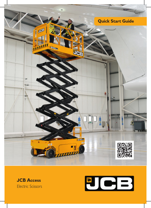
Quick Start Guide JCB AccessElectric Scissors1Operation Transporting the MachineAX – X axis distance Y – Y axis distanceourmeterlatform Raise / Lower Toggle Switchmergency Stopround Controls / Off / Platform Controls Key Switch Please see operator manual for full details./ R Steeringrigger Switch to enable operation attery Level / Fault Code Display latform / Drive Mode Buttonspeed Selectmergency Stoprake Release Lockrake Release PumpHow to Release BrakesEnsure machine can be controlled before releasing brakesPush in brake release lockPump brake release until feels solidCaution – machine is now un-brakedTo reapply pull the brake release lock back out or operate any control on the joystick4Switch Key Left Toggle SwitchTurn the key switch left to enable the ground controls. Use the toggle switch to raise or lower the platform as required.Note: If the platform raise/lower fails to operate, ensure the key switch is in the correct position and all of the emergency stops have been pulled to release.457Trigger & JoystickCradle Release Mode SelectOperate Machine Pull the trigger on the back of the joystick to enable operation.The cradle can be released from the platform by removing the bolt.If CH is shown on the platform controller, the key switch is in the wrong position. The switch must be on platform controls to use them. The machine will Choose from either lift/lower or drive mode. Do not attempt to operate prior to charge status being shown.Pressure SensorsPothole Protection SwitchLimit SwitchesOnly use the original charger installed to the machine with the original batteries. Charge the battery in a well ventilated place. Use an appropriate grounded industrial power supply with correct AC (alternating current) input voltage to charge.If at any time a fault occurs when charging, three battery charge LEDs will blink at the same time. Refer to the operators handbook immediately.AC harge Point C harger Viewing WindowThe flashing LED indicates the charge level. When all three LEDs are solid, the machine is fully charged.Code Description Reaction Instructions 01System intialisation fault Disables all motion Restart the machine 02System communication fault Disables all motion Restart the machine 03Invalid option setting fault Disables all motion Restart the machine 04Load sensing data faultWarning only Contact the dealer 12Chassis up or down switch ON at power-up faultDisable chassis control Contact the dealer 18Pothole guard fault Check pothole protection 31Pressure sensor 1 fault 32Angle sensor fault 36Limp mode42Platform left turn switch ON atpower-up message 43Platform right turn switch on atpower-up message 46Platform joystick enable switch on atpower-up fault 47Platform joystick not in neutral at power-upDiagnostic codes are shown on both the platform controller and through a viewing window on the hydraulic tray door.JCB Sales Limited, Rocester, Staffordshire, United Kingdom ST14 5JP Tel:+441889590312Email:***************** Download the very latest information on this product range at: All rights reserved. No part of this publication may be reproduced, stored in a retrieval system, or transmitted in any form or by any other means, electronic, mechanical, photocopying or otherwise, without prior permission from JCB Sales. All references in this publication to operating weights, sizes, capacities and other performance measurements are provided for guidance only and may vary dependant upon the exact specification of the machine. They should not therefore be relied upon in relation to suitability for a particular application.Guidance and advice should always be sought from your JCB Dealer’. JCB reserves the right to change specifications without notice. Illustrations and specifications shown mayinclude optional equipment and accessories.9818/3000。
CX-TGK01型电脑时间控制开关

CX-TGK01型微电脑时间控制开关使用说明书一、产品简介:CX-TGK01型微电脑时间控制开关,是一个以微电脑为核心,配合电子电路等组成的一个电源开关控制装置。
它可设定每天或一周内20次不同时间的开/关控制,还具有倒计时(延时关机)、随机、夏时制和12/24小时制转换功能。
本机内置一枚可充电镍氢电池作为备用电源,在脱离市电电源的情况下,仍可保持计时显示和储存的各项数据达6个月以上。
它采用输入输出接线形式,可以控制路灯、灯箱、电热水器、烘箱等各种安装位置固定的电器设备。
如和交流接触器串联后可控制大功率电器和三相电器设备。
您使用本产品后,各种电器将会根据您的要求实现自动开启和关闭。
二、技术参数:执行标准:GB/T14536.1-1998 GB/T14536.8-1996额定电压:220V ~50HZ额定电流:20A(阻性)工作温度:-10~55℃计时误差:<±2秒/天动作形式:1.B.S.U三、系统功能介绍:1.液晶全屏字符和外形尺寸,如右图所示:2. 本机在时钟状态下,按“模式”键可将工作状态设定为所需的方式。
设定顺序为:关自动开随机 Z Z(倒计时)关电源输出处于经常关闭状态。
自动电源输出处于执行编写的定时开/关程序状态。
开电源输出处于经常开启状态。
随机电源输出处于随机开启和关闭状态。
间隔时间为40~80分钟,开启时间为1~15分钟。
Z Z电源输出处于倒计时延时关机状态,最长时间为 2小时59分,最短为1分钟。
C按此键后系统将清除所有储存的数据,系统恢复到初始状态。
四、操作方法(一)、校正星期和时间:按“模式”键将定时器工作状态设定为“关”或“开”,在此状态下左手按住“时钟”键不放,右手按“星期”键,将星期调整为当前日期,调整好日期(星期)后再按“时”和“分”键将时钟调整为当前的标准时间。
(二)、设定倒计时(延时关机)工作状态:按“模式”键将工作状态切换至Z Z(倒计时)状态,电源输出即处于开启状态,屏幕显示如右图所示:在此状态下,按“时”或“分”键修改您所需要本机开启通电的时间,每按一次“时”或“分”键,时间将减少1小时或1分钟。
第一部分、TKGK-1产品使用说明

第一部分产品使用说明TKGK-1过程控制实验装置组成和各部分使用说明TKGK-1型过程控制实验装置是根据自动化专业及相关专业教学的特点,吸收了国外同类实验装置的特点和长处,经过精心设计,多次实验和反复论证,向广大师生推出一套全新的实验设备。
该设备可以满足《过程控制》、《自动化仪表》、《工程检测》、《计算机控制系统》等课程的教学实验。
整个系统结构紧凑、功能多样、使用方便,既能进行验证性、研究性实验,又能提供综合性实验。
本实验装置可满足本科、大专及中专等不同层次的教学实验要求,还可为科学研究开发提供实验手段。
本实验装置的控制信号及被控信号均采用IEC标准,即电压0~5V或1~5V,电流0~10mA或4~20mA。
实验系统供电要求为单相交流220V±10%,10A;外型尺寸为:167*164*73,重量:580Kg。
装置特点本实验装置具有以下特点:1、多种被控参数:温度、压力、流量、液位。
2、控制方式多样:位式控制、模拟PID控制、智能仪表控制、单片机控制、PLC控制、计算机控制等。
3、多种计算机控制软件:PROTOOL-CS组态软件、MCGS组态软件、本公司开发的上位机监控软件。
4、丰富的计算机控制算法:P、PI、PID、死区PID、积分分离、不完全积分、模糊控制、神元控制、基于SIMULINK的动态参数自适应补偿控制等。
5、开放的软件平台:在我们提供的软件平台上,学生既可以利用我们所提供的算法程序进行实验,又可以用自己编写的PLC程序、MATLAB算法程序等进行实验。
6、灵活多样的实验组合:可以很方便地对控制方式与被控参数进行不同组合,得到自己需要的单回路、多回路等多种控制系统。
系统组成TKGK-1型过程控制实验装置集多参数闭环控制为一体,它是由被控对象、调节器模块、执行器模块、变送器模块和单片机控制模块等组成,各模块间组合灵活,基本包含了目前所有的工业控制方式,涉及温度、压力、流量和液位等重要的过程控制参数。
KQC-C超载限制器使用说明书

超载限制器KQC-C使用说明书(Ⅵ)2013年2月版●使用前请仔细阅读本产品说明书●请妥善保管本产品说明书,以备查阅宁波柯力传感科技股份有限公司目录第一章概述 (2)第二章技术参数 (2)第三章安装连接 (3)第四章键盘功能介绍 (4)第五章操作方法 (5)第六章操作简要(开机操作即可使用) (6)第七章标定及参数设置 (8)第八章参数设置菜单说明 (11)第九章常见故障及解决方法 (12)附表 1 KQC-C超载限制器装箱清单 (13)第一章概述KQC-C型超载限制器是一种新型智能式重量过载保护器,通过设置的重量传感器测量装载物重量的变化,KQC-C仪表实时显示实际载荷,当载荷达到其额定载荷的设定值时,发出声光报警信号,并可给出开关量输出。
KQC-C型超载限制器体积较小,带有安装卡槽,并可外接小型显示板或大屏幕。
KQC-C型超载限制器具有结构合理、安装方便、调试操作简单、工作可靠、精度高等一系列优点。
采用单个传感器时可用于塔机、卷扬机等;采用两个传感器时可用于施工升降机。
带有标准卡槽,可安装于控制柜中。
第二章技术参数⏹工作电源:AC220V/50Hz;⏹综合误差:≤5%F.S.;⏹供桥电源:DC5V;⏹继电器输出触点容量:10A/250VAC;⏹输入信号范围:0mV--15mV;⏹最大净输入信号:≤15mV;⏹显示位数:4位;⏹大屏幕输出波特率600bps;⏹工作温度:-20℃-60℃;⏹仪表尺寸:115mm*90mm*72mm;⏹仪表重量:0.5kg⏹推荐预热时间:≥10min;第三章安装连接由于KQC-C型超载限制器采用了带有接线端子的工业机箱,因此安装极为简单。
在超载限制器的内部有6个接线端子,他们用来完成超载限制器的外部连接,如下表所示,具体接线如超载限制器上盖前后面贴提示说明所示。
接口编号连接备注1报警器正极报警器2报警器负极3220VAC火线220V电源4未用5220VAC零线6继电器常开端过载开关7继电器公共端8继电器常闭端9外接显示负极外接显示10外接显示信号11外接显示正极12传感器激励正13传感器信号正超载传感器114传感器信号负15传感器激励负16传感器激励正17传感器信号正超载传感器218传感器信号负19传感器激励负注:1、安装仪表时,请严格按照上盖前后面贴提示进行连接;接单个传感器时,另一路传感器接口须信号线短接;2、强制开关在正常情况下禁止使用,如遇特殊情况,超载后仍需继续工作,可打开强制开关。
- 1、下载文档前请自行甄别文档内容的完整性,平台不提供额外的编辑、内容补充、找答案等附加服务。
- 2、"仅部分预览"的文档,不可在线预览部分如存在完整性等问题,可反馈申请退款(可完整预览的文档不适用该条件!)。
- 3、如文档侵犯您的权益,请联系客服反馈,我们会尽快为您处理(人工客服工作时间:9:00-18:30)。
CJTKC电动操作机构安装使用说明书0TK.466.5018泰开集团山东泰开隔离开关有限公司二〇一一年六月目录目录 (1)一、机构的主要特点 (2)二、CJTKC电动机构技术参数表: (3)三、使用环境条件 (3)四、结构和工作原理 (3)1、结构 (3)2、机构安装尺寸及外形尺寸 (4)3、工作原理 (6)五、安装和调试 (6)1、安装前检查 (6)2、调试步骤: (6)3、角度调节: (7)六、常见故障处理: (8)1、电动操作不动作 (8)2、接触器不动作或有异常声音 (8)七、储存: (8)八、注意事项 (8)九、随机文件 (9)十、订货须知 (9)CJTKC电动机构A相二次原理图(非汇控相) (10)CJTKC电动机构A相二次接线图(非汇控相) (11)CJTKC电动机构B相二次原理图(汇控相) (12)CJTKC电动机构B相二次原理图(汇控相) (13)CJTKC电动机构C相二次原理图(非汇控相) (14)CJTKC电动机构C相二次原理图(非汇控相) (15)附录:电动机构投运的条件 (16)CJTKC电动机操动机构是交流380V三相电动机驱动,通过蜗轮、蜗杆两级减速或齿轮及蜗轮、蜗杆三级传动的操动机构,可以用来驱动800kV及1100kV等电压等级的户外隔离开关和接地开关。
一、机构的主要特点1、适用性强:CJTKC电动机构可配用800kV及1100kV户外隔离开关和接地开关;2、CJTKC电动机构可靠性高:2.1传动系统操作平稳,冲击力小、自锁可靠、噪音低;2.2机构的限位装置可有效防止分、合到位后输出轴可能发生的继续转动,保证隔离开关(接地开关)不受损伤;2.3机构的联锁装置可以满足多种联锁及五防闭锁功能,能有效防止误操作;3、机构采用不锈钢板焊接而成,结构合理、外形美观,并具有有效的防锈、防腐功能。
4、箱盖采用凸台式机构,能有效的加固箱体;5、箱体与输出轴的密封采用油封及气体迷宫的双层密封结构,箱门的密封采用的是箱变折弯及气囊密封结构,能起到很好的防水、防尘效果,满足防护等级IP54的要求;凸台式顶盖机构防水机构6、机构整体机构简单,布局合理,零部件具有很强的互换性。
机构的正门和侧门可以在任意时候打开,方便的进行检查维护或更换零件;7、机构与隔离开关(接地开关)联结采用夹板式,不需焊接。
机构与传动杆的连接示意图二、C JTKC电动机构技术参数表:1、周围空气温度:-50℃—+50℃;2、海拔:3000m及以下;3、风压:不超过700Pa;4、地震烈度:不超过8度;5、污秽等级:不大于Ⅳ级;6、不适用于有易燃物质,爆炸危险,化学腐蚀及剧烈震动的场所;7、不适用于非水平安装的场所。
四、结构和工作原理1、结构传递给机构主轴,安装时借助于钢管连接使隔离开关或接地开关分合闸。
机构由电动机、机械减速传动系统、电气控制系统、加热系统、联锁装置及箱体组成。
1.1 电动机为三相交流异步电动机。
1.2根据电动机构所使用的位置不同,机械减速传动系统采用集成的双蜗轮蜗杆结构及齿轮及双蜗轮蜗杆结构进行减速,密封式结构,6007航空润滑脂。
具有操作平稳、冲击力小、噪音低、自锁可靠、外形美观、重量轻等优点。
1.3电气控制系统包括电源开关(低压断路器)、分合停控制按钮、接触器、电机保护器、远方就地选择开关、行程开关、温度湿度控制器、辅助开关、加热器、接线端子、照明灯、汇控分相选择开关(根据实际选择)。
如用户需要还可配置等其他电器元件,只需在合同中注明即可。
(a)辅助开关为F9型,供用户电气联锁及信号指示用,接点对数可按用户要求供应。
常规为10常开10常闭。
(b)为避免电动机因意外故障而过载烧坏,本机构装有低压断路器和电机保护器对电动机进行保护。
(c)为保证手动操作人员安全,本机构在装手柄处设有手动闭锁开关。
1.4 机构通过“联锁”接点,可以满足与其他设备的相互闭锁;1.5 为满足手动操作力的要求,在减速器原手动操作位置增加省力装置,有效降低手动操作力,提高现场调节的可操作性;1.6箱体为不锈钢焊接拉丝,采用三侧开门结构。
其外形美观、结构合理,具有可靠的防水、防尘、防腐及防锈蚀性。
对各种地域均能适应,与传统的铆接和螺栓连接结构相比,更为轻巧和美观。
2、机构安装尺寸及外形尺寸CJTKC电动机构的安装尺寸为250³300,详见外型及安装尺寸图。
3、工作原理CJTKC电动机构的控制原理图附后;3.1单相电气控制操作:首先,将机构手动摇至分合中间位置,将机构中“汇控、分相”旋钮指向“分相”,将“远方、就地”指向“就地”位置,然后接通三相电源,电动操作时,注意机构输出轴运动方向(或开关运动方向)与输入指令是否一致,如机构运动方向与要求相反,应立即按下停止按钮,更换电源进线相序,再次进行电动操作;3.2三相联动电气控制操作:在保证单相电动操作正确的情况下,将三相电动机构按照与单相操作时相同的相序接入电源,将A、B、C三相电动机构中的“汇控、分相”旋钮指向“汇控”,将“远方、就地”指向“就地”位置,接通电源,进行电动操作,如需停止,可直接按下B相机构中的“停止”按钮;在“就地”操作试验后,将“汇控、分相”旋钮指向“汇控”,“远方、就地”指向“远方”位置,然后进行后台汇控操作;五、安装和调试1、安装前检查为确保安全可靠运行,安装前应进行下列检查方可安装。
1.1 拆箱后检查机构外观是否完整,铭牌数据与订货要求是否相符。
1.2 检查机构箱内附件是否齐全,如手柄、合格证、说明书等。
1.3 用手柄进行数次空载分合操作,检查机构传动是否正常,行程开关和辅助开关切换是否正常。
1.4 接通电源,电动操作数次,检查机构动作是否正常。
注意:首次使用新电源进行电动操作前,应先将机构置于合、分中间位置。
再进行电动操作,检查输出轴选择方向是否正确,若不正确应立即按下“停止”按钮,在端子排处调节相序。
2、调试步骤:2.1在隔离开关(或接地开关)安装完毕后,将机构挂装在基础架上,先不要紧固机构背面的四个安装螺栓,然后用铅锤找好机构主轴和隔离开关(或接地开关)传动主轴使之同心,最后将安装螺栓固紧。
2.2 配好隔离开关转动主轴与机构输出轴之间的传动杆,用接头连接。
用手动操作机构,后使隔离开关(或接地开关)和机构都处于合闸终点位置,然后将紧固接头松开,手动将电动机构手动回转6—8圈,然后紧固接头螺栓,再进行操作几次,确保隔离开关(或接地开关)和机构分合正常。
2.3 按相应的接线图连接控制线,检查无误后接通电源进行电动试操作。
在电动操作前,应先将机构手摇至分合闸中间位置,拉下手动闭锁滑板,再按分、合闸按钮检查电动机旋转方向是否正确,若发现隔离开关(或接地开关)运动方向与指令不符,应立即切断电源,将三相电源任意二相互换一下,再重复以上过程,至转向正确。
电动连续操作分合数次,必须保证隔离开关(或接地开关)和机构分合动作正常,控制回路电气联锁、导电接触可靠,各有关连接部分无松动现象,机械传动平稳可靠,无异常声响。
2.4 电动操作完毕,检查各连接部位可靠拧紧,并作紧固标志。
2.5 检查控制回路联锁关系正确,加热、照明回路工作正常。
3、角度调节:当开关要求电动机构输出角度有变化时,可通过移动行程开关在扇形导轨中的位置进行调整,以达到调整电动机构输出角度的目的。
例如:如下图所示此时如需要增大输出角度,可以先将固定螺栓2松至扇形板1能自由转动,然后将扇形板1向行程止挡6处移动少量行程,使之行程止挡3的行程量增加,达到增大输出角度的目的;(注:允许最大调节量分合两侧各±5°)角度调节示意图下几点:4.1 有手柄操作机构,检查传动系统是否灵活,行程开关、辅助开关能否正常切换,分、合闸指示是否正确;4.2 连接部分,紧固件有无松动;4.3 控制回路、辅助开关、行程开关、接触器、电动机构保护器、空气开关等,电器元件有无损坏,接触是否良好;4.4 箱门的密封是否可靠、牢固。
六、常见故障处理:1、电动操作不动作可能原因:(1)电机电源或控制电源断相、电源没接通或与机构实际不符;(2)控制回路或电机回路不通;(3)接线头有松动,存在虚接;处理方式:(1)使用万用表检测电机电源、控制电源是否已经提供与机构铭牌标识相同的电源;(2)检查电机回路与控制回路是否断路①、试验时“联锁”及“五防”是否短接(需要接联锁时将短接线拆除);②、检查机构行程开关是否正常转换,“远方、就地”“汇控、分相”是否处于正确位置;(3)将虚接线压紧;2、接触器不动作或有异常声音可能原因:(1)接触器接线不良;(2)接触器触头或内部有异物;(3)控制回路短路;处理方式:(1)检查接触器接线是否存在虚接;(2)清理接触器触电和磁铁吸合接触面;(3)按照二次图纸及“电机检查”方式进行检查回路;七、储存:产品启封后如不立即安装或要长期存放时,须存放在干燥有遮蔽场所。
如储藏需要超过6个月,建议定期使用加热器给机构加热去潮。
八、注意事项1、当进行手动操作时,先将手动闭锁滑至露出手动操作孔,将手柄插入进行操作;拔出手柄将手动后,确保闭锁滑板回复至原位置时,方可进行电动(或远动)操作。
2、除调试及检查电动机操动机构外,严禁内门未关闭时操作电动机操动机构;3、为防止意外,现场在正门把手处必须加挂明锁;4、机构正常运行时,严禁用手直接触摸加热器,以防烫伤。
九、随机文件本机构采用木箱包装,机构本体、手柄及随机文件均装在一个箱内。
本机构一般随隔离开关成套供应,根据用户需求也可以单独供应,每台机构的随机文件见表。
十、订货须知订购CJTKC电动机操动机构时应注明以下内容:1、型号、规格和数量;1.1主轴输出转角及操作时间;1.2控制电压、电动机电压及电源性质;1.3辅助开关的触点对数(不指明时为只配辅助开关10开10闭);1.4是否配备其他特殊电器元件。
1.5是否采用三相汇控操作。
2、除以上各项外,用户若还有其它特殊要求,在订货时也应指明。
3、我公司电动操作机构除CJTKC以外,还配有用于110kV及以下产品的CJTKB电动机构、用于550kV以下、110kV以上的CJTKA电动机构;4、产品到货后,应及时进行验收,如发现有问题,应立即与我方联系,以便及时处理。
欢迎企业选购我厂产品,并热忱希望您对我企业的产品提出宝贵的意见和建议。
J D MJ D M附录:电动机构投运的条件电动机构投运所需要具备的条件包括:1、电机电源、控制电源与电动机构铭牌刻制的实际所需电源一致;2、电机电源相序正确,单相及三相联动时,机构能正确完成指令;3、电动机构“远方、就地”、“汇控、分相”电动操作均能正确完成工作指令;4、电动机构的手动闭锁位置闭合;5、端子排中“五防闭锁”、“联锁”两处预留端子,用户已经接入联锁线或已经短接;6、机构与隔离开关的连杆连接已经紧固;7、检查各位置紧固螺栓及其他固定件连接完成;8、检查其他相关设备;。