DCA电容式说明书
DCA产品介绍

谢谢参阅
主要产品介绍(5)
SGC1000 MBE 系统
l l l l l l l l l l l l 最大12英寸(300mm)样片 液氮冷却板 4个电子枪 最多可达6个泄流盒 垂直腔室 30KeV RHEED 800L/s 离子泵 10英寸低温泵 1000L/s 分子泵 钛升华泵(TSP) 带机械式晶片传送的超高真空(UHV)套件 带分子泵的盒式真空进片室
DCA分子束外延及高 真空薄膜沉积系统
宇丰凯电子科技有限公司
DCA 公司简介
DCA Instruments 是一家专业从事分子束外 延(MBE)和超高真空薄膜沉积系统及组件的 设计和制造的公司。DCA Instruments自1989年 成立以来,已经在全球范围内安装了超过100 套的超高真空系统。 DCA Instruments绝大部分的产品都是针对 用户定制设计复杂的沉积系统,该公司许多的标 准系统最初都是起源于针对某些客户对沉积过 程特殊需求的解决方案,因此在标准系统制造业 中有着深厚的为用户定制设计的背景,在用户 中具有很好的声誉。
主要产品介绍(3)
M600 MBE系统 l 最大4英寸样片 l 液氮冷却板 l 2个电子枪 l 最多可达8个泄流盒 l 垂直腔室 l 30KeV RHEED l 500L/s 离子泵 l 8英寸低温泵 l 1000L/s 分子泵 l 钛升华泵(TSP) l 带300L/s 离子泵的超高真空(UHV)缓冲室 l 带分子泵的盒式真空进片室
主要产品介绍(1)
R450(R450C) MBE系统 l l l l l l l l l l l 最大3英寸样片 双区域液氮冷却板 8个泄流盒 倾斜的腔室设计 15KeV RHEED 500L/s 离子泵 8英寸低温泵 500L/s 分子泵 钛升华泵(TSP) 带300L/s 离子泵的超高真空(UHV)缓冲室 带分子泵的真空进片室
TDK-EPCOS C0802C104KA53A 电容器说明书
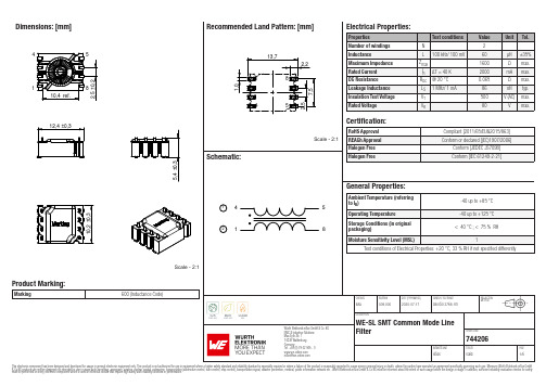
Dimensions: [mm]Scale - 2:1Product Marking:Marking600 (Inductance Code)B CT e m p e r a t u r eT pT LCautions and Warnings:The following conditions apply to all goods within the product series of WE-HCFA ofWürth Elektronik eiSos GmbH & Co. KG:General:•This electronic component is designed and manufactured for use in general electronic equipment.•Würth Elektronik must be asked for written approval (following the PPAP procedure) before incorporating the components into any equipment in fields such as military, aerospace, aviation, nuclear control, submarine, transportation (automotive control, train control, ship control), transportation signal, disaster prevention, medical, public information network etc. where higher safety and reliability are especially required and/or if there is the possibility of direct damage or human injury.•Electronic components that will be used in safety-critical or high-reliability applications, should be pre-evaluated by the customer. •The component is designed and manufactured to be used within the datasheet specified values. If the usage and operation conditions specified in the datasheet are not met, the wire insulation may be damaged or dissolved.•Do not drop or impact the components, the component may be damaged.•Würth Elektronik products are qualified according to international standards, which are listed in each product reliability report. Würth Elektronik does not warrant any customer qualified product characteristics beyond Würth Elektronik’s specifications, for its validity and sustainability over time.•The responsibility for the applicability of the customer specific products and use in a particular customer design is always within the authority of the customer. All technical specifications for standard products also apply to customer specific products.Product specific:Soldering:•The solder profile must comply with the technical product specifications. All other profiles will void the warranty.•All other soldering methods are at the customers’ own risk.•Strong forces which may affect the coplanarity of the components’ electrical connection with the PCB (i.e. pins), can damage the part, resulting in avoid of the warranty.Cleaning and Washing:•Washing agents used during the production to clean the customer application might damage or change the characteristics of the wire insulation, marking or plating. Washing agents may have a negative effect on the long-term functionality of the product.•Using a brush during the cleaning process may break the wire due to its small diameter. Therefore, we do not recommend using a brush during the PCB cleaning process.Potting:•If the product is potted in the customer application, the potting material might shrink or expand during and after hardening. Shrinking could lead to an incomplete seal, allowing contaminants into the core. Expansion could damage the component. We recommend a manual inspection after potting to avoid these effects.Storage Conditions:• A storage of Würth Elektronik products for longer than 12 months is not recommended. Within other effects, the terminals may suffer degradation, resulting in bad solderability. Therefore, all products shall be used within the period of 12 months based on the day of shipment.•Do not expose the components to direct sunlight.•The storage conditions in the original packaging are defined according to DIN EN 61760-2.•The storage conditions stated in the original packaging apply to the storage time and not to the transportation time of the components. Handling:•Violation of the technical product specifications such as exceeding the nominal rated current will void the warranty.•Applying currents with audio-frequency signals may result in audible noise due to the magnetostrictive material properties.These cautions and warnings comply with the state of the scientific and technical knowledge and are believed to be accurate and reliable.However, no responsibility is assumed for inaccuracies or incompleteness.Würth Elektronik eiSos GmbH & Co. KGEMC & Inductive SolutionsMax-Eyth-Str. 174638 WaldenburgGermanyCHECKED REVISION DATE (YYYY-MM-DD)GENERAL TOLERANCE PROJECTIONMETHODIMA009.0002020-07-17DIN ISO 2768-1mDESCRIPTIONWE-SL SMT Common Mode LineFilter ORDER CODE744206BUSINESS UNIT STATUS PAGEImportant NotesThe following conditions apply to all goods within the product range of Würth Elektronik eiSos GmbH & Co. KG:1. General Customer ResponsibilitySome goods within the product range of Würth Elektronik eiSos GmbH & Co. KG contain statements regarding general suitability for certain application areas. These statements about suitability are based on our knowledge and experience of typical requirements concerning the areas, serve as general guidance and cannot be estimated as binding statements about the suitability for a customer application. The responsibility for the applicability and use in a particular customer design is always solely within the authority of the customer. Due to this fact it is up to the customer to evaluate, where appropriate to investigate and decide whether the device with the specific product characteristics described in the product specification is valid and suitable for the respective customer application or not.2. Customer Responsibility related to Specific, in particular Safety-Relevant ApplicationsIt has to be clearly pointed out that the possibility of a malfunction of electronic components or failure before the end of the usual lifetime cannot be completely eliminated in the current state of the art, even if the products are operated within the range of the specifications.In certain customer applications requiring a very high level of safety and especially in customer applications in which the malfunction or failure of an electronic component could endanger human life or health it must be ensured by most advanced technological aid of suitable design of the customer application that no injury or damage is caused to third parties in the event of malfunction or failure of an electronic component. Therefore, customer is cautioned to verify that data sheets are current before placing orders. The current data sheets can be downloaded at .3. Best Care and AttentionAny product-specific notes, cautions and warnings must be strictly observed. Any disregard will result in the loss of warranty.4. Customer Support for Product SpecificationsSome products within the product range may contain substances which are subject to restrictions in certain jurisdictions in order to serve specific technical requirements. Necessary information is available on request. In this case the field sales engineer or the internal sales person in charge should be contacted who will be happy to support in this matter.5. Product R&DDue to constant product improvement product specifications may change from time to time. As a standard reporting procedure of the Product Change Notification (PCN) according to the JEDEC-Standard inform about minor and major changes. In case of further queries regarding the PCN, the field sales engineer or the internal sales person in charge should be contacted. The basic responsibility of the customer as per Section 1 and 2 remains unaffected.6. Product Life CycleDue to technical progress and economical evaluation we also reserve the right to discontinue production and delivery of products. As a standard reporting procedure of the Product Termination Notification (PTN) according to the JEDEC-Standard we will inform at an early stage about inevitable product discontinuance. According to this we cannot guarantee that all products within our product range will always be available. Therefore it needs to be verified with the field sales engineer or the internal sales person in charge about the current product availability expectancy before or when the product for application design-in disposal is considered. The approach named above does not apply in the case of individual agreements deviating from the foregoing for customer-specific products.7. Property RightsAll the rights for contractual products produced by Würth Elektronik eiSos GmbH & Co. KG on the basis of ideas, development contracts as well as models or templates that are subject to copyright, patent or commercial protection supplied to the customer will remain with Würth Elektronik eiSos GmbH & Co. KG. Würth Elektronik eiSos GmbH & Co. KG does not warrant or represent that any license, either expressed or implied, is granted under any patent right, copyright, mask work right, or other intellectual property right relating to any combination, application, or process in which Würth Elektronik eiSos GmbH & Co. KG components or services are used.8. General Terms and ConditionsUnless otherwise agreed in individual contracts, all orders are subject to the current version of the “General Terms and Conditions of Würth Elektronik eiSos Group”, last version available at .Würth Elektronik eiSos GmbH & Co. KGEMC & Inductive SolutionsMax-Eyth-Str. 174638 WaldenburgGermanyCHECKED REVISION DATE (YYYY-MM-DD)GENERAL TOLERANCE PROJECTIONMETHODIMA009.0002020-07-17DIN ISO 2768-1mDESCRIPTIONWE-SL SMT Common Mode LineFilter ORDER CODE744206BUSINESS UNIT STATUS PAGE。
高压切换挡朗电容器说明书
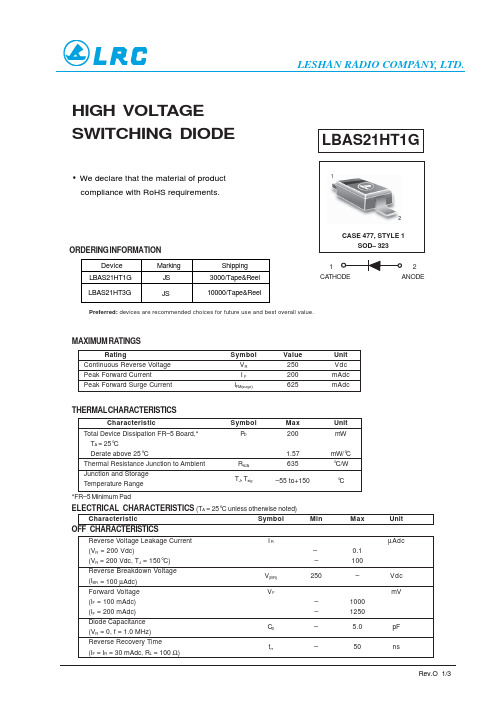
HIGH VOL T AGESWITCHING DIODECASE 477, STYLE 1SOD– 32312LBAS21HT1GANODE1CA THODEMAXIMUM RATINGSRatingSymbol Value Unit Continuous Reverse Voltage V R 250Vdc Peak Forward CurrentI F 200mAdc Peak Forward Surge CurrentI FM(surge)625mAdcTHERMAL C HARACTERISTICSCharacteristicSymbol Max Unit Total Device Dissipation FR–5 Board,*P D200mW T A = 25°CDerate above 25°C1.57mW/°C Thermal Resistance Junction to Ambient R θJA 635°C/W Junction and Storage T J , T stg–55 to+150°CTemperature Range *FR–5 Minimum PadELECTRICAL CHARACTERISTICS (T A = 25°C unless otherwise noted)CharacteristicSymbol MinMaxUnit OFF CHARACTERISTICSReverse Voltage Leakage Current I RµAdc(V R (V R = 200 Vdc, T J = 150°C)–100Reverse Breakdown Voltage V (BR)250–Vdc (I BR = 100 µAdc)Forward Voltage V FmV(I F = 100 mAdc)–1000(I F = 200 mAdc)–1250Diode Capacitance C D – 5.0pF (V R = 0, f = 1.0 MHz)Reverse Recovery Time t rr–50ns(I F = I R = 30 mAdc, R L = 100 Ω)Preferred: devices are recommended choices for future use and best overall value.• DeviceMarkingShipping LBAS21HT1G JS 3000/Tape&Reel LBAS21HT3GJS10000/Tape&ReelWe declare that the material of productcompliance with RoHS requirements.0.1 = 200 Vdc)–ORDERING INFORMATIONLBAS21HT1G700060005000400030006543210125102050100200300I R , R E V E R S E C U R R E N T (n A )1200100080060040020011101001000V F , F O R W A R D V O L T A G E (m V )Figure 1. Forward Voltage I F , FORWARD CURRENT (mA)V R , REVERSE VOLTAGE (V)Figure 2. Reverse LeakageNotes: 1. A 2.0 k Ω variable resistor adjusted for a Forward Current (I F ) of 30 mA.2. Input pulse is adjusted so I R(peak) is equal to 30 mA.3. t p » t rrV Rrt10%90%I I OUTPUT PULSE (I F = I R = 30 mA; measuredat i R(REC) = 3.0 mA)INPUT SIGNALFigure 1. Recovery Time Equivalent Test CircuitSOD-323LBAS21HT1GH E NOTES:1.DIMENSIONING AND TOLERANCING PER ANSI Y14.5M, 1982.2.CONTROLLING DIMENSION: MILLIMETERS.3.LEAD THICKNESS SPECIFIED PER L/F DRAWING WITH SOLDER PLATING.4.DIMENSIONS A AND B DO NOT INCLUDE MOLD FLASH, PROTRUSIONS OR GATE BURRS.5.DIMENSION L IS MEASURED FROM END OF RADIUS.NOTE 3DIM MIN NOM MAX MILLIMETERSA 0.800.90 1.00A10.000.050.10A30.15 REF b 0.250.320.4C 0.0890.120.177D 1.60 1.70 1.80E 1.15 1.25 1.350.082.30 2.50 2.70L 0.0310.0350.0400.0000.0020.0040.006 REF0.0100.0120.0160.0030.0050.0070.0620.0660.0700.0450.0490.0530.0030.0900.0980.105MIN NOM MAX INCHESSOLDERING FOOTPRINT*Reel DimensionsMetric Dimensions Govern –– English are in parentheses for reference onlyEMBOSSED TAPE AND REEL DATAFOR DISCRETESAT MaxOutside Dimension Measured at EdgeGInside Dimension Measured Near Hub20.2mm Min (.795’’)1.5mm Min(.06’’)13.0mm ± 0.5mm(.512 ±.002’’)50mm Min (1.969’’)Full RadiusSize A Max GT Max 8 mm330mm (12.992’’)8.4mm+1.5mm, -0.0(.33’’+.059’’, -0.00)14.4mm (.56’’)LESHAN RADIO COMPANY, LTD.Storage ConditionsTemperature: 5 to 40 Deg.C (20 to 30 Deg. C is preferred) Humidity: 30 to 80 RH (40 to 60 is preferred )Recommended Period: One year after manufacturing(This recommended period is for the soldering condition only. The characteristics and reliabilities of the products are not restricted to this limitation)Shi p ment S p ecification10 Reel12 Inner Box/Carton 360KPCS/CartonDim(Unit:mm)Dim(Unit:mm)10Reel/Inner Box30KPCS/Inner Box460mm*400mm*420mm8000PCS/Reel (SOT-723,SOD-723)3000PCS/Reel80KPCS/Inner Box (SOT-723,SOD-723)960KPCS/Carton (SOT-723,SOD-723)LESHAN RADIO COMPANY, LTD.。
DCAP系列操作维护说明

前言北京清华紫光测控生产的DCAP-3000系列综合自动化系统是通过部级鉴定,通过国家继电器质量监视检验中心检验的产品,是国家电力部检验和认证的产品,是国家经贸委城乡电网改造中第一批推荐使用的产品。
它代表清华大学在高新技术控制领域的强劲实力,以其先进的技术力量和优质的效劳态度赢得了广阔用户的一致好评,实践也证明,它是一种让广阔用户信赖的产品。
但任何产品在使用过程中是不可防止的要处理一些小故障,给用户带来一些麻烦,为了方便用户能正确、积极的操作及处理我公司产品的问题,我公司针对用户在使用DCAP-3000系列监控保护装置的过程中提出的一些问题和要求进展了罗列和整理,并将在操作和维护中有可能出现的问题进展了分析,制作了本维护手册,以便用户能够更加熟悉地使用该产品。
当然,紫光公司也不会满足现有的状态,在广阔用户的监视下,它一定会取得更加完美的成绩,开发生产出让广阔用户更加信服的产品。
该说明用于操作和维护人员在使用该产品时作为参考资料,如有模棱两可的问题,希望用户尽快和我公司联系,以便能更好的解决问题。
本说明不详之处,敬请各位指出,以便我公司补充。
谢谢!说明:该手册配合技术说明书和补充说明一起使用。
北京清华紫光测控日常维护系统在安装调试完毕后,应该定期对设备进展日常维护,维护的频度根据具体使用条件而定。
日常维护要点包括环境检查、工作状况检查和部件检查及清理等内容。
工作环境包括温度、湿度、干净度等。
温度:环境温度关系到综自系统运行的有效寿命和稳定可靠性;长时间的高温下工作可能导致系统运行的有效寿命大大降低,同时使诸如出口继电器等元器件的性能大大下降。
设备长期运行的温度一般不高于25C°,最低长期运行温度一般不低于-5 C°。
相对湿度:相对湿度影响到系统的绝缘和系统的防护性能。
湿度大直接导致绝缘电阻的降低,同时长时间的相对湿度大将导致线路和元器件受到侵蚀,甚至破坏系统的正常工作状态。
一般长期运行的相对湿度在75%左右。
电容器型号参考手册说明书

Ordering Information: Order by complete part number, as below. For other options,write your requirements on your quote request or purchase order.Cast-Case Part Numbering SystemOrdering Information27130B 470J O 0CDE Rated Peak Capacitance Capacitance Temperature Range Mounting StyleType Voltage Tolerance O = –55 °C to +125 °C 0 = No mounting plate10 = 100030 = 3000250 = 25000470 = 47 pF 361 = 360 pF 122 = 1200 pFG = ±2%J = ±5%1 = Mounting plate on bottom only2 = Mounting plates on top and bottomCharacteristicHigh-Voltage Types Ordering Information, Mica CapacitorsTemp. Coeff. ppm/°C Capacitance Drift Standard Cap. RangeB Not specified Not specifiedC –200 to +200 ±(0.5% +0.1pF) 1–18 pFD –100 to +100 ±(0.3% +0.1pF) E– 20 to +100±(0.1% +0.1pF)20–82 pFMilitary Style NumbersFor the commercial equivalent to military style numbers CM66 through CM93 see the tables below.Military Style No.Equivalent CDE TypeMilitary Style No.Equivalent CDE TypeCM66 271, Mounting Style 0 CM81 292, Mounting Style 0 CM67 271, Mounting Style 1 CM82 292, Mounting Style 1 CM68 271, Mounting Style 2CM83 292, Mounting Style 2 CM70F2CM86 293, Mounting Style 0 CM71 272, Mounting Style 0 CM87 293, Mounting Style 1 CM72 272, Mounting Style 1 CM88 293, Mounting Style 2 CM73 272, Mounting Style 2 CM91 294, Mounting Style 0 CM76 291, Mounting Style 0 CM92 294, Mounting Style 1 CM77 291, Mounting Style 1CM93294, Mounting Style 2CM78291, Mounting Style 2Potted Case StylesTransmitting mica capacitor type 272 is available in potted case package Type F2. To order this potted style use the part numbering below and contact us.F230B 470JMCDE Rated Peak Capacitance Capacitance Temperature RangeType Voltage Tolerance M = –55 °C to +70 °C(in hundredsof peak work-ing volts)470 = 47 pF 361 = 360 pF 122 = 1200 pFG = ±2%J = ±5% (standard)CharacteristicType 271Type 273Type 272Type 292Type 291Type 293Type 294MOUNTING STYLE 0MOUNTING STYLE 1MOUNTING STYLE 2TOLERANCES UNLESSOTHERWISE SPECIFIED:±.031MOUNTING STYLE 0MOUNTING STYLE 1MOUNTING STYLE 2MOUNTING STYLE 0MOUNTING STYLE 1MOUNTING STYLE 2MOUNTING STYLE 0MOUNTING STYLE 1MOUNTING STYLE 2MOUNTING STYLE 0MOUNTING STYLE 1MOUNTING STYLE 2MOUNTING STYLE 0MOUNTING STYLE 1MOUNTING STYLE 2Cast-Case StylesCapacitance is within tolerance when measured at these frequencies:1–1000 pF @ 1 MHz> 1000 pF @ 1 kHz Dissipation Factor is typically less than 0.05% when measured as above. Dissipation factor (DF) equals 2πfRC, where f is the test frequency, R is the equivalent series resistance (Ω), and C is nominal capacitance (F). Q is the reciprocal of the dissipation factor. Operating Temperature Range is –55 °C to +125 °C. Insulation Resis-tance is no less than 7500 MΩ when measured at 100 Vdc. Temperature Coefficient and Ca-pacitance Drift: Measure the capaci-tors’ capacitance at 25 °C, 55 °C, 25 °C, 125 °C, and at 25 °C after stabi-lizing at each temperature. The ca-pacitance will meet the limits of the Characteristic table shown in Order-ing Information.Rated Peak Voltage is not to be ex-ceeded in actual use. Voltage ratings are in the listings and apply under the following conditions:Temperature: Within the specified operating temperature range.Altitude: Up to 50,000 feet or3.4 inches of mercury.Relative Humidity: Up to 80%. Frequency: As specified.Where pulse conditions are en- countered, contact us. Withstanding Voltage:Capacitors will withstand application of an ac potential between terminals having an rms value equal to the rated peak voltage at a frequency of 100 Hz or less without damage, arcing or break-down. Apply the potential by raising the voltage from zero to the specified value. Apply the full potential for a minimum of 5 seconds.Case Insulation: Capacitor cases willwithstand, without damage, arcing orbreakdown, a 60-Hz peak ac potentialequal to twice the rated peak voltageapplied between the terminals con-nected together and a metal electrodetouching the case. Apply this poten-tial for 1to 5 seconds.Current Ratings at various fre-quencies are in the listings and ap-ply under the following conditions:Temperature: 65 °C maximumDerating Factor: NoneVibration:Capacitors will with-stand vibrational forces occurringat rates of from 10 to 55 Hz for 4½hours. The total excursion during vi-bration is 0.06 inches. At the end ofthis period, make the following in-spections and tests:Visual and Mechanical Inspection:No perceptible deterioration. With-standing Voltage: As specified underWithstanding Voltage.Insulation Resistance: No less than7500 MΩ.Capacitance Change: Not to exceed3% of the nominal value or one pico-farad, whichever is greater.Temperature and Immersion Cy-cling:Capacitors will withstand thetemperature and immersion cyclesindicated in the tables below. Fol-low three temperature cycles by twoimmersion cycles. Make the measure-ments listed below no more than 30minutes following the final immer-sion cycle:Withstanding Voltage: As specifiedunder Withstanding Voltage.Insulation Resistance: No less than7500 MΩ.Capacitance: Change not to exceed4% of the nominal value or one pico-farad, whichever is greater.Temperature Cycling Test Condi-tionsSteps Temp Interval(°C) (Minutes)1 –55 + 0 30–32 25 +10 10 to 15–53 125 + 3 30–04 25 +10 10 to 15–5Immersion Test Conditions•Number of cycles: 2•Duration of each immersion: 15minutes•Immersion bath: Saturated solu-tion of sodium chloride and water•Temp. of hot bath: 65 –0 +5 ºC•Temp. of cold bath: 25 –0 +10 ºCLife Test: Subject all capacitors toa temperature of 55 °C for 48 hours.Then subject units cast in rectan-gular cases (Types 271, 272, and273) to a 60-Hz rms voltage equalto the rated peak voltage for 250hours. Subject units cast in cylindri-cal cases (Types 291, 292, 293, and294) to a 60-Hz rms voltage equalto 90% of the rated peak voltage for250 hours. In both tests, maintainthe temperature at 125 °C. Aftertest, the capacitors will meet theserequirements:Withstanding Voltage: As specifiedunder Withstanding Voltage.Insulation Resistance: No less than7500 MΩ.Capacitance Change: Within thelimits given in the table below orone picofarad, whichever is greater.Characteristic Maximum Cap.B ±8%C ±3%D ±3%E ±3%In addition, the capacitor must showno visual damage and the markingsmust be legible.Specifications。
超级电容器产品说明书

....................................................................... SPECIFICATIONSMODEL NO.: PCX-10F10 Farad Hybrid Super Capacitor with 3-Digit Blue Voltage Meter Capacitance.............................. 10,000.000 micro farad (10 Farad)Working Voltage........................................... 16 DCVSurge Voltage................................................. 20 DCVE. S. R. (Equivalent Series Resistance)......... 0.0015 ohm @ 120Hz / 25°CCapacitance Tolerance....................................± 10 %MODEL NO.: PCX-20F20 Farad Hybrid Super Capacitor with 3-Digit Blue Voltage Meter Capacitance.............................. 20,000.000 micro farad (20 Farad)Working Voltage........................................... 16 DCVSurge Voltage................................................. 20 DCVE. S. R. (Equivalent Series Resistance)…..... 0.0015 ohm @ 120Hz / 25°CCapacitance Tolerance...................................± 10 %MODEL NO.: PCX-30F30 Farad Hybrid Super Capacitor with 3-Digit Blue Voltage Meter Capacitance.............................. 30,000.000 micro farad (30 Farad)Working Voltage........................................... 16 DCVSurge Voltage................................................. 20 DCVE. S. R. (Equivalent Series Resistance)……. 0.0015 ohm @ 120Hz / 25°CCapacitance Tolerance...................................± 10 %DETAILED FEATURES:a) 3 digit super bright blue voltage meter measures 0.1V DVC range.b) Blue LED lighting window illuminates, and goes to sleep status when the amplifier isswitched off and there’s no voltage variation within 3 minutes.c) Reverse polarity connection warning buzzer. If the capacitor is connected incorrectlyby reversing the positive and negative wires during the installation process, the buzzer on the PCB will ring till you correct polarity connection.d) Over voltage limit and low battery voltage limit warning. When the system voltagegoes ABOVE 17 DCV or BELOW 10 DCV, the buzzer will issue warning sound.INSTALLATION AND MOUNTING:Securely mount the capacitor using supplied hardware. Be careful when choosing mounting location to avoid moving parts and possible exposure to moisture.CHARGING THE CAPACITOR AND WIRING:The capacitor must be charged before connecting the Power and Ground cables to the capacitor. Failure to charge the capacitor will result in a large spark generated from the rapid inflow of current.1. To charge the capacitor:Make capacitor positive terminal connections with amplifier and tighten the bolt. Do not over-tighten the bolt!Caution: Stripped terminals are not covered under the capacitor’s warranty.2. Connect the ground cables of the battery, amplifier, and capacitor separately tochassis.3. Place the supplied charging resistor between the positive terminal of the capacitor andthe battery’s positive terminal. After 5~60 seconds, the capacitor will be fully charged.Caution: The resistor will become hot!4. Immediately after the charging process, take away the charging bulb from theconnecting wire, and connect the positive cable to the positive terminal on the capacitor.CAPACITOR WIRING DIAGRAM:DISCHARGING THE CAPACITOR:Never remove the capacitor without discharging the stored power – it can give adangerous electrical shock!To disconnect the capacitor, follow these instructions:1. Disconnect the cables from the capacitor in the following order:a) positive (+) cableb) ground (-) cable2. Holding the resistor provided, touch the leads to the positive (+) and ground (-)terminals of the capacitor. After 1~5 minutes, the capacitor will be discharged (Thecharging resistor will become hot!) Then you can safely remove and handle it.WARNING!!THIS POWER CAPACITOR MAY EXPLODE AND CAUSE SERIOUS INJURY IF ABUSEDOR CONNECTED IMPROPERLY. PLEASE REFER TO THE INSTRUCTIONS CONTAINEDIN THIS MANUAL FOR CORRECT OUNTING, CHARGING/DISCHARGING AND WIRINGCONNECTION FOR THIS CAPAPCITOR PRIOR TO INSTALLATION.POWER ACOUSTIK AUDIO ACCESSORIES CAR AUDIO ACCESSORIES。
DCAP-3232N技术说明书

第七章DCAP-3232多功能备用电源自投装置1. 基本配置DCAP-3232多功能备用电源自投装置(以下简称装置)主要用于母线分段开关的备用电源自投或进线开关的备用电源自投,系统示意图如下。
装置根据系统的运行方式确定备自投的动作方式。
完备的自投功能:●四种方式的分段自投功能●双向进线自投功能●故障录波测控功能:●10路遥信开入采集、装置遥信变位、事故遥信●三条进线断路器遥控跳、合●2路脉冲量输入通讯功能:●智能通讯卡:常规配置高速RS485现场总线,通讯速率可达115.2Kbps,并支持双网。
也可选配工业以太网2. 技术数据2.1.额定数据直流电源:220V±20% 或 110V±20%交流电压:100/3V,100V交流电流:5A或1A频率:50Hz2.2.功率消耗:直流回路:正常≤15W跳闸≤20W交流电压回路:<0.5VA/相(额定57.74V时)交流电流回路:<0.5VA/相(额定5A时)2.3.定值误差:电流及电压定值误差:<±5%整定值频率定值误差:<0.02Hz时间定值误差:✧无延时段<30ms±10ms✧定时限延时段<±1%整定时间+30ms2.4.遥测量计量等级:电压,电流: 0.5级频率: 0.02HZP,Q,COSΦ:1级遥信分辨率:小于2ms电能计量精度:0.5级GPS对时精度:<1ms3.工作原理3.1.分段备自投 (方式一~方式四)装置引入两段母线电压,用于有压、无压判别。
为防止PT三相断线后造成分段开关误投,每个进线开关各引入一相电流。
装置引入1DL、2DL、3DL开关位置接点,作为系统运行方式判别,自投准备及选择自投方式。
装置还设有有压定值、无压定值,及四种分段自投方式的整定控制字。
●方式一充电条件:a)Ⅰ母、Ⅱ母均三相有压b)1DL、2DL在合位,3DL在跳位在上述条件全部满足15S后,充电完成。
放电条件:a)3DL在合位b)Ⅰ母、Ⅱ母均无压c)有外部闭锁信号上述条件有其一满足,则放电。
DCAP-5024电容器组自动投切控制装置使用说明书
湖南紫光测控有限公司 2010-07-01
DCAP-5024 电容器组自动投切控制装置使用说明书
目
录
1 装置概述 ....................................................................................................................................... 3 2 主要功能 ....................................................................................................................................... 3 3 使用说明 ....................................................................................................................................... 3 3.1 交流电压输入回路 .......................................................................................................... 3 3.2 交流电流输入回路 .......................................................................................................... 3 3.3 直流电源输入回路 ................................................
- 1、下载文档前请自行甄别文档内容的完整性,平台不提供额外的编辑、内容补充、找答案等附加服务。
- 2、"仅部分预览"的文档,不可在线预览部分如存在完整性等问题,可反馈申请退款(可完整预览的文档不适用该条件!)。
- 3、如文档侵犯您的权益,请联系客服反馈,我们会尽快为您处理(人工客服工作时间:9:00-18:30)。
外形尺寸:如下图所示
探极
长度
棒式探极缆式探极同轴探极平面探极丝路
数
码
标
定
技
术
全
能
解
决
方
案
产品描述
LS-DCA型射频电容式物位限位开关(下
称限位开关)是一种新型的物位仪表。
由于采用了“射频技术”和“数码标定技术”,解决了长期以来电容式物位限位开关在使用中温漂大、不易标定的两大难题,特别是“数码标定技术”属国内外首创,它必将推动电容式物位限位开关更广泛地应用于各行各业。
本物位限位开关可对块状、颗粒状、粉末状及液态物料料仓的料位及液位进行控制或上、下限位报警,适用于高温、高压、强腐蚀、多粉尘的恶劣环境;在冶金、石油、化工、轻工、煤炭、水泥、粮食等行业中应用广泛。
工作原理
当传感器安装于仓体上时,探极和仓壁分别相当于电容器的两个极板;由于被测物料的介电常数与空气不同,所以仓内物位发生变化时会引起探极对仓壁间的电容量发生变化,当该电容量大于用户的设定值时,限位开关内的继电器动作,输出一个开关量达到控制(或报警)的目的。
★工作环境:温度 -30—70℃ / -30—85℃
湿度≤90%
★电源电压:AC 220V±10% 50Hz / DC 24V ★功耗:≤1W
★输出信号:一组继电器接点输出(触点容
量 AC 220V 1A, )
★输出延时:内部输出延时1~3秒。
★安装结构:与传感器一体化结构。
★普通型:仓内温度:-30-100℃
仓内压力:常压。
仓内介质:无腐蚀性,一般粘
度,一般冲击。
★特殊型:仓内温度:-30-600℃
仓内压力:小于6Mpa
仓内介质:强腐蚀,高粘度,
强冲击、防爆。
★安装接头:R1/R1.5 管螺纹。
仪表的接线
上/下限位选择
接线端子
仪表面板分布图 ◆接线端子——端子“1”、“2”接AC 220V 或DC 24V 电源,端子“3”、“4”为继电器接点输出。
◆上/下限位选择——上/下限位由拨动开关设置,开关拨至右边为 “上限位”状态,输出继电器为 有料吸合;开关拨至左边为 “下限位”状态,输出继电器为空料吸合。
出厂设置为上限位。
调试方法
用户应在确定传感器探头未被物料埋没条件下进行标定,具体标定步骤如下:
第一步:确认探头未被物料埋没(空仓或物料距离探头50cm 以上),上电30分钟。
第二步:观察 “频率显示值”并记录此数值。
第三步:用该“频率显示值”减去50便得出“动作频率值”;然后用小改锥将“动作频率值”设置到
“动作频率设定”旋转数码开关上,至此标定结束。
注:如传感器作为下限位检测,将“上/下限位”选择开关置于下限位位置。
丝
路
数码标定技术
全能解决方案
安装方法
如安装示意图所示,限位开关通常采用侧装(在仓壁侧面安装)方式安装于仓体侧壁对料位高度进行上下限位置的检测,当仓体不便侧面开孔时可采用顶装(在仓的顶部
安装)方式。
顶装时电极距仓壁距离应大于200mm,应选择能避开进料时物料冲击的位置。
仓壁为混凝土时应使限位开关外壳可
靠接通钢筋,仓壁为非金属时应加装辅助探极(对于固体物料)或使用同轴探极(对于液体)。
注:用户拆装限位开关时禁止用手抱住壳体
拧动,应使用扳手拧动六角螺栓。
上限位(顶装)
上限位 (侧装)
下限位 (侧装)。