FPGA可编程逻辑器件芯片XQR2V3000-4CG717V中文规格书
FPGA可编程逻辑器件芯片XC3S2000-4FG1156C中文规格书

Chapter 16Boot ModesThe Versal™ ACAP boot modes are designed for maximum flexibility. This chapter provides aprimary boot mode summary, selection considerations, and interface details. The primary bootmodes in the PMC are:•JTAG Boot Mode•Quad SPI Boot Mode•SD Boot Modes•eMMC1 Boot Mode•Octal SPI Boot Mode•SelectMAP Boot ModeEach boot mode uses a set of I/O pins and has a voltage requirement that can affect post-boot peripheral use of shared MIO on a bank. The best overall boot mode solution for an application considers the overall system requirements, performance, cost, and complexity.The boot modes are categorized into master or slave boot modes. The master boot modesautomatically load the programmable device image from a memory source (SD, eMMC, quad SPI, or octal SPI). The master boot modes provide a basic solution with easy setup. In master bootmodes, the POR_B pin release to the first fetch from a boot device is estimated at ~620 μs. This time guides how quickly the flash must be ready to respond to the BootROM. The slave bootmodes require an external processor or controller to load the programmable device image with a command set (JTAG or SelectMAP). An advantage of using a slave boot mode is that the device image can reside almost anywhere in the host system or over a network connection. The slaveboot modes are multipurpose interfaces that can also be used for system debug and readback.RECOMMENDED: Regardless of the boot mode selected, if the secure boot flow is not used, then JTAGconnectivity on the board is recommended for the application. JTAG connectivity is a valuable debuggingand bring-up interface.Table 11: Minimum Flash Component Size for Primary Boot with One PDI (cont'd)Series Device Minimum Boot Flash Capacity(Mbits)Versal AI Core VC1352512 VC15021024 VC17021024 VC18021024 VC19021024Boot HeaderThe boot header in the PDI is read by the ROM code unit (RCU) to determine key information such as the platform loader and manager (PLM) location and size, the boot mode bus width, and security encryption key details. The boot header format information is listed in the followingtable. For additional information on the PDI format, boot header, boot header attributes, meta header, or partition headers see Bootgen User Guide (UG1283).Table 12: Boot Header FormatOffset (Hex)Size (Bytes)Description Details0x0016SelectMAP bus width Used to determine if the SelectMAP bus width is x8, x16, or x32See SelectMAP Pattern and Bit Order for the unique entries.0x104QSPI bus width QSPI bus width description.This is required to identify the QSPI flash in single/dual stacked or dual parallel mode. 0xAA995566 in the little endian format.0x144Image identification Boot image identification stringContains 4 bytes X, N, L, X in byte order, which is 0x584c4e58 in the little endian format.0x184Encryption key source This field is used to identify the AES key source: 0x00000000 - Unencrypted0xA5C3C5A3 - eFUSE red key0xA5C3C5A5 - eFUSE black key0x3A5C3C5A - BBRAM red key0x3A5C3C59 - BBRAM black key0xA35C7C53 - Boot header black key0x1C4PLM source offset PLM source start address in PDI 0x204PMC data load address PMC CDO address to load0x244PMC data length PMC CDO length0x284Total PMC data length PMC CDO length including authentication and encryption overhead0x2C4PLM length PLM original image sizeTable 12: Boot Header Format (cont'd)Offset (Hex)Size (Bytes)Description Details 0x304Total PLM length PLM image size including the authentication and encryption overhead 0x344Boot header attributes Boot header attributes 0x6412Secure header IV Secure header initialization vector 0x704PUF shutter value Length of time the PUF samples before it closes the shutter 0x7412Secure header IV for PMC data The IV used to decrypt secure header of PMC data 0x8068Reserved Populate with zeroes 0xC44Meta header offset Offset to the start of the meta header 0xC8-0x12488Reserved 0x1282048Register init Stores register write pairs for system register initialization 0x9281544PUF helper data PUF helper data 0xF304Checksum Header checksum 0xF3476SHA3 padding SHA3 standard paddingSection III: Platform Boot, Control, and StatusChapter 15: Boot Image。
FPGA可编程逻辑器件芯片XC3S4000-4FGG676C中文规格书

<delay until after PCIe reset is released>// Deassert EOS to simulate the starting of the 2nd stage bitstream loadingforce board.EP.pcie_ip_support_i.pcie_ip_i.inst.startup_i.EOS = 1'b0;<delay a minimum of 4 user_clk cycles>// Reassert EOS to simulate that 2nd stage bitstream completed loadingforce board.EP.pcie_ip_support_i.pcie_ip_i.inst.startup_i.EOS = 1'b1;// Simulate as normal from this point on.The hierarchy to the PCIe core in the line above must be changed to match that of the user design. This line can also be found in the example simulation provided with the core in the file named board.v.Calculating Bitstream Load Time for TandemThe configuration loading time is a function of the configuration clock frequency and precision, data width of the configuration interface, and bitstream size. The calculation is broken down into three steps:1.Calculate the minimum clock frequency based on the nominal clock frequency andsubtract any variation from the nominal.Minimum Clock Frequency = Nominal Clock - Clock Variation2.Calculate the minimum PROM bandwidth, which is a function of the data bus width,clock frequency, and PROM type. The PROM bandwidth is the minimum clock frequency multiplied by the bus width.PROM Bandwidth = Minimum Clock Frequency × Bus Width3.Calculate the first-stage bitstream loading time, which is the minimum PROM bandwidthfrom step2, divided by the first-stage bitstream size as reported bywrite_bitstream.Stage 1 Load Time = (Stage 1 Bitstream Size) / (PROM Bandwidth)The stage 1 bitstream size, reported by write_bitstream, can be read directly from the terminal or from the log file.The following is a snippet from the write_bitstream log showing the bitstream size for stage 1 in a VU095 device:Creating bitstream...Tandem stage1 bitstream contains 9175424 bits.Tandem stage2 bitstream contains 277708576 bits.Writing bitstream ./xilinx_pcie_ip.bit...These values represent the explicit values of the bitstream stages, whether in one bit file or two. The effects of bitstream compression are reflected in these values.Example 1The configuration for Example 1 is:•Quad SPI flash (x4) operating at 66 MHz ± 200 ppm•Stage 1 size = 9175424 bits = 8.75 MbThe steps to calculate the configuration loading time are:1.Calculate the minimum clock frequency:66 MHz × (1 - 0.0002) = 65.98 MHz2.Calculate the minimum PROM bandwidth:4 bits × 65.98 MHz = 263.92 Mb/s3.Calculate the first-stage bitstream loading time:8.75 Mb / 263.92 Mb/s = ~0.0332 s or 33.2 msExample 2The configuration for Example 2 is:•BPI (x16) Synchronous mode, operating at 50 MHz ± 100 ppm•Stage 1 size = 9175424 bits = 8.75 MbThe steps to calculate the configuration loading time are:1.Calculate the minimum clock frequency:50 MHz × (1 - 0.0001) = 49.995 MHz2.Calculate the minimum PROM bandwidth:16 bits × 49.995 MHz = 799.92 Mb/s3.Calculate the first-stage bitstream loading time:8.75 Mb / 799.92 Mb/s = ~0.0109 s or 10.9 msUsing Bitstream CompressionMinimizing the stage 1 bitstream size is the ultimate goal of Tandem Configuration, and the use of bitstream compression aids in this effort. This option uses a multi-frame write technique to reduce the size of the bitstream and therefore the configuration time required. The amount of compression varies from design to design. When Tandem is selected,Chapter 3:Designing with the Core compression is turned on in the IP level constraints. This can be overridden in the user design constraints as desired. The following command can be used to enable or disable bitstream compression.set_property PRESS <TRUE|FALSE> [current_design]Other Bitstream Load Time ConsiderationsBitstream configuration times can also be affected by:•Power supply ramp times, including any delays due to regulators•T POR (power on reset)Power-supply ramp times are design-dependent. Take care to not design in large ramp times or delays. The FPGA power supplies that must be provided to begin FPGA configuration are listed in UltraScale Architecture Configuration User Guide (UG570) [Ref7]. In many cases, the FPGA power supplies can ramp up simultaneously or even slightly before the system power supply. In these cases, the design gains timing margin because the 100ms does not start counting until the system supplies are stable. Again, this is design-dependent. Systems should be characterized to determine the relationship between FPGA supplies and system supplies.T POR is 57 ms for standard power ramp rates, and 20 ms for fast ramp rates for UltraScale devices. See Kintex UltraScale Architecture Data Sheet: DC and AC Switching Characteristics (DS892)[Ref8], and Virtex UltraScale Architecture Data Sheet: DC and AC Switching Characteristics (DS893) [Ref9].Consider two cases for Example 1 (Quad SPI flash [x4] operating at 66 MHz ± 200 ppm) from Calculating Bitstream Load Time for Tandem:•Case 1: Without ATX Supply•Case 2: With ATX SupplyAssume that the FPGA power supplies ramp to a stable level (2 ms) after the 3.3V and 12V system power supplies. This time difference is called T FPGA_PWR. In this case, because the FPGA supplies ramp after the system supplies, the power supply ramp time takes away from the 100 ms margin.The equations to test are:T POR + Bitstream Load Time + T FPGA_PWR < 100 ms for non-ATXT POR + Bitstream Load Time + T FPGA_PWR - 100 ms < 100 ms for ATX。
FPGA可编程逻辑器件芯片EP4CGX75CF23I7N中文规格书

Chapter 2:Logic Array Blocks and Adaptive Logic Modules in Arria II DevicesAdaptive Logic ModulesFigure2–6 shows a detailed view of all the connections in an ALM.Figure2–6.Connection Details of the Arria II ALMOne ALM contains two programmable registers. Each register has data, clock, clockenable, synchronous and asynchronous clear, and synchronous load and clear inputs.Global signals, general purpose I/O (GPIO) pins, or any internal logic can drive theregister’s clock and clear-control signals. Either GPIO pins or internal logic can drivethe clock enable. For combinational functions, the register is bypassed and the outputof the LUT drives directly to the outputs of an ALM.Each ALM has two sets of outputs that drive the local, row, and column routingresources. The LUT, adder, or register output can drive the ALM outputs (refer toFigure2–6). For each set of output drivers, two ALM outputs can drive column, row,or direct link routing connections, and one of these ALM outputs can also drive localinterconnect resources. The LUT or adder can drive one output while the registerdrives another output.Arria II Device Handbook Volume 1: Device Interfaces and IntegrationChapter 6:I/O Features in Arria II DevicesI/O BanksI/O BanksArria II GX devices contain up to 16 I/O banks as shown in Figure6–1. The left I/Obanks are dedicated for high-speed transceivers. Bank 3C and 8C are dedicated forconfiguration pins. The rest of the banks are user I/O banks that support allsingle-ended and differential I/O standards.Figure6–1.I/0 Banks in Arria II GX Devices(Note1), (2), (3), (4), (5), (6), (7)Notes to Figure6–1:(1)Banks GXB0, GXB1, GXB2, and GXB3 are dedicated banks for high-speed transceiver I/Os.(2)Banks 3C and 8C are dedicated configuration banks and do not have user I/O pins.(3)LVDS with DPA is supported at banks 5A, 5B, 6A, and 6B.(4)Differential HSTL and SSTL inputs use LVDS differential input buffers without R D OCT support.(5)Differential HSTL and SSTL outputs are not true differential outputs. They use two single-ended outputs with the second output programmed asinverted.(6)Figure6–1 is a top view of the silicon die that corresponds to a reverse view for flip chip packages. It is a graphical representation only.(7)The PLL_CLKOUT pin supports only emulated differential I/O standard but not true differential I/O standard.Arria II Device Handbook Volume 1: Device Interfaces and IntegrationChapter 3:Memory Blocks in Arria II DevicesMemory FeaturesFigure3–2 shows how the wren and byteena signals control the operations of theMLABs. Falling clock edges triggers the write operation in MLABs.Figure3–2.Byte Enable Functional Waveform for MLABsPacked Mode SupportArria II M9K and M144K blocks support packed mode. The packed mode featurepacks two independent single-port RAMs into one memory block. The Quartus IIsoftware automatically implements the packed mode where appropriate by placingthe physical RAM block into true dual-port mode and using the MSB of the address todistinguish between the two logical RAMs. The size of each independent single-portRAM must not exceed half of the target block size.Address Clock Enable SupportArria II memory blocks support address clock enable, which holds the previousaddress value for as long as the signal is enabled (addressstall = 1). When youconfigure the memory blocks in dual-port mode, each port has its own independentaddress clock enable. The default value for the address clock enable signal is low(disabled).Arria II Device Handbook Volume 1: Device Interfaces and Integration。
FPGA可编程逻辑器件芯片XQVR300-4CB228V中文规格书

Reconfiguration and MultiBootMultiBoot OverviewBecause Spartan®-6 FPGAs are reprogrammable in the system, some applications reloadthe FPGA with one or more bitstream images during normal operation. In this way, asingle smaller FPGA, reprogrammed multiple times, replaces a much larger and moreexpensive ASIC or FPGA programmed just once.A variety of methods can be used to reprogram the FPGA during normal operation. Thedownloaded configuration modes inherently provide this capability. Via an external“intelligent agent,” such as a processor, microcontroller, computer, or tester, an FPGA canbe reprogrammed numerous times. The downloaded modes are available on allSpartan-6FPGA families.Spartan-6 FPGAs include a capability called MultiBoot that allows the FPGA to selectivelyreprogram and reload its bitstream from an attached external memory. The MultiBootfeature allows the FPGA application to load two or more FPGA bitstreams under thecontrol of the FPGA application. The FPGA application triggers a MultiBoot operation,causing the FPGA to reconfigure from a different configuration bitstream. After aMultiBoot operation is triggered, the FPGA restarts its configuration process as usual. TheINIT_B pin pulses Low while the FPGA clears its configuration memory, and the DONEoutput remains Low until the MultiBoot operation successfully completes.MultiBoot is supported in SPI x1, x2, x4, and BPI configuration modes.Spartan-6 FPGA Configuration User Guide UG380 (v2.11) March 22, 2019Chapter 7:Reconfiguration and MultiBootFallback MultiBootFallback BehaviorSpartan-6 FPGAs have dedicated MultiBoot logic, which is used for both fallback and MultiBoot (IPROG) reconfiguration. When fallback or IPROG happens, an internallygenerated pulse resets the entire configuration logic, except for the dedicated MultiBoot logic and the BOOTSTS, MODE, and GENERAL1.5 registers. See Figure 7-1. This reset pulse pulls INIT_B and DONE Low, and restarts the configuration process by clearing configuration memory.During configuration, a CRC error or a watchdog timer time-out error can trigger fallback. The watchdog timer is only active in master configuration modes. The time-out value is user configurable using the BitGen -g TIMER_CFG switch. The switch is followed by a 16-bit value (greater than 16h'0201) indicating the number of configuration clocksallowed before detection of the Sync word times out.During fallback reconfiguration, the FPGA increments the strike count, stored in theBOOTSTS register, and continues reconfiguration if the strike count is less than the limit permitted for that image. If the limit is not reached, the FPGA checks the NEW_MODE bit in the MODE register. If this value is 0, the device uses the configuration mode defined by the mode pins. If the value is 1, the device uses the configuration mode defined in the BOOTMODE bits in the MODE register. The NEW_MODE register is set by the BitGen option -g Next_Config_New_Mode:Yes . The BOOTMODE bits are set by the BitGen option -g Next_Config_Boot_Mode .Figure 7-1:MultiBoot LogicSpartan-6 FPGA Configuration User Guide UG380 (v2.11) March 22, 2019Fallback MultiBootThere are three images for MultiBoot configuration. The first image is the Header. This small bitstream contains the sync word, sets the addresses for the next bitstream as well as the fallback or golden bitstream, and ends with an IPROG command. To generate this bitstream automatically, add the BitGen option -g next_config_addr when creating the programming file for the golden bitstream.The second image is the MultiBoot bitstream. This is the bitstream that the user plans to configure first. The location of this bitstream is defined by the values of GENERAL1,2. The upper eight bits of the GENERAL 2 register are reserved for the opcode for the non-volatile device. See Chapter5, Configuration Details, for more information.The third image is the fallback or golden bitstream. This bitstream is known to be “safe” should an error occur consistently during configuration. The location of this bitstream is defined by the values of GENERAL3,4. As with GENERAL1,2, the upper eight bits of GENERAL4 are reserved for the opcode of the non-volatile device.If the configuration fallback occurs and the golden bitstream is reached, the only way to boot back into the MultiBoot bitstream (located at GENERAL1,2) is to toggle the PROGRAM_B pin, power cycle the device, or use IPROG reconfiguration (see IPROG Reconfiguration, page136)For designs that use more than two bitstreams, the GENERAL1,2 values must be set to the location of the next bitstream then an IPROG command needs to be issued. GENERAL3,4 values should be reserved for the fallback bitstream.The header image must start at address 0. This image has three “strikes” allotted to it. If a CRC error is detected, the strike count increments and configuration restarts if the register setting RESET_ON_ERROR is 1 (located in the register COR2, and can be set from BitGen setting -g Reset_on_err) and the strike count is less than 3. The same behavior occurs if the watchdog timer times out, but it does not depend on RESET_ON_ERROR. The strike counter is found in the BOOTSTS registers. If the count is 3, configuration halts with INIT and DONE driven Low. To clear the strike count, perform a hard reboot (pulse the PROGRAM_B pin) or cycle power.The MultiBoot image can reside at any address specified in GENERAL1,2. This image has three “strikes” allotted to it. If an error is detected, the strike count increments and configuration will restart at the address specified in GENERAL1,2 if the count is less than 3 and RESET_ON_ERROR is 1. If the count hits 3, configuration moves to the fallback bitstream located at GENERAL3,4. There are two ways to clear the strike count: power cycle the FPGA or pulse the PROGRAM_B pin.The fallback (or golden) image can reside at any address specified in GENERAL3,4. This image has 3 strikes allotted to it. If an error is detected, the strike count increments and configuration will restart at the address specified in GENERAL3,4 if the count is less than 6.The value is 6 because it shares the strike counter with the MultiBoot image. If the count reaches 6, configuration boots back to zero, where the header image is located. When this occurs, configuration will attempt both the MultiBoot image and the fallback image three more times before halting configuration. This results in a strike count of 9.After successful fallback reconfiguration, the user design should readback the STATUS or BOOTSTS registers to verify the fallback was successful. Successful fallback configuration maintains the strike count register, and a subsequent soft reboot uses the address stored in GENERAL3,4 (the golden image). There are two ways to clear the strike count: perform a hard reboot (pulse the PROGRAM_B pin) or cycle power.If fallback reconfiguration exhausts all three strikes out, configuration stops and both INIT_B and DONE are held Low.Fallback is disabled if AES is enabled and for Slave configuration mode.Spartan-6 FPGA Configuration User Guide UG380 (v2.11) March 22, 2019Chapter 7:Reconfiguration and MultiBootIPROG ReconfigurationThe IPROG (internal PROGRAM_B) command has similar effect as a pulsingPROGRAM_B pin, except IPROG does not reset the dedicated reconfiguration logic. The start address set in GENERAL1,2 is used during reconfiguration instead of the default address (zero). The fallback (golden) bitstream address is set in GENERAL3,4. The IPROG command can be sent through ICAP_SPARTAN6 or the bitstream.Reboot Using ICAP_SPARTAN6The IPROG command can also be sent using the ICAP_SPARTAN6 primitive. After a successful configuration, the user design determines the start address of the MultiBoot bitstream, and sets the GENERAL1,2 registers, and then issues an IPROG command using ICAP.The sequence of commands is:1.Send the Sync word.2.Program the GENERAL1,2 registers for the next bitstream start address and the non-volatile device opcode for a read operation. Also program the GENERAL3,4 registersfor the fallback (golden) bitstream start address and the opcode for the non-volatiledevice for a read operation.3.Send the IPROG command.Table 7-1 shows an example bitstream for the IPROG command using ICAP.Table 7-1:Example Bitstream for IPROG through ICAP ConfigurationData (hex)(1)Explanation FFFFDummy Word AA99Sync Word 5566Sync Word 3261Type 1 Write 1 Words to GENERAL_1XXXXMultiBoot Start Address [15:0]3281Type 1 Write 1 Word to GENERAL2(2)XXXXOpcode and MultiBoot Start Address [23:16]32A1Type 1 Write 1 Word to GENERAL3XXXXFallback Start Address [15:0]32C1Type 1 Write 1 Word to GENERAL4(2)XXXXOpcode and Fallback Start Address [23:16]30A1Type 1 Write 1 Word to CMD 000EIPROG Command 2000Type 1 NO OPNotes:1.SelectMAP 16-bit data ordering applies to the ICAP data bus. See Table 2-5, page 40 for proper bit ordering.2.The eight most significant bits of GENERAL2 and GENERAL4 registers represent the opcode for the read instruction for the non-volatile storage device. Consult the data sheet of the storage device for the proper opcode. Common codes are 0x0B , 0x3B , and 0x6B for Fast Read, Dual Fast Read, and Quad Fast Read, respectively.Spartan-6 FPGA Configuration User Guide UG380 (v2.11) March 22, 2019Status Register for Fallback and IPROG ReconfigurationAfter the configuration logic receives the IPROG command, the FPGA resets everythingexcept the dedicated reconfiguration logic, and the INIT_B and DONE pins go Low. Afterthe FPGA clears all configuration memory, INIT_B goes High again. Then the value inGENERAL1,2 is used for the bitstream starting address.IPROG does not reset the strike count. MultiBoot applications that use IPROG throughICAP_SPARTAN6 should pulse PROGRAM_B or implement a power cycle after aconfiguration error that increments the strike count. Otherwise, verify that externalmemory is properly updated to avoid configuration errors that would increment the strikecount.Status Register for Fallback and IPROG ReconfigurationSpartan-6 devices contain a BOOTSTS that stores configuration history. At EOS or an errorcondition, Status_0 is updated with the current status. If fallback or MultiBoot occurs,Status_1 is updated at EOS or an error condition. The Valid_0 bit indicates if the rest ofStatus_0 is valid or not. The BOOTSTS register is written either at an End Of Startup (EOS)event or a fallback event. The EOS event happens after the first configuration attempt. Asuccessful MultiBoot operation via the IPROG command does not result in the BOOTSTSregister being updated. See Boot History Status Register (BOOTSTS), page110.Table7-2 through Table7-4show the BOOTSTS values in some common situations.Table 7-2:Status after First Bitstream Configuration without ErrorCRC_ERROR ID_ERROR WTO_ERROR IPROG FALLBACK VALID Status_1000000Status_0000001Table 7-3:First Configuration followed by IPROGCRC_ERROR ID_ERROR WTO_ERROR IPROG FALLBACK VALID Status_1000001Status_0000101Table 7-4:IPROG Embedded in First Bitstream, Second Bitstream CRC Error, andFallback SuccessfullyCRC_ERROR(1)ID_ERROR WTO_ERROR IPROG FALLBACK VALID Status_1(2)000111Status_0(3)100101Notes:1.CRC_Error only registers CRC errors detected during initial configuration. CRC_Error is not updatedif CRC errors are found from the Readback CRC (POST_CRC) function.2.Status_1 shows a fallback bitstream was loaded successfully. The IPROG bit was also set in this case,because the fallback bitstream contains an IPROG command. Although the IPROG command isignored during fallback, the status still records this occurrence.3.Status_0 shows IPROG was attempted, and a CRC_ERROR was detected for that bitstream.。
FPGA可编程逻辑器件芯片XC2V3000-4BG957CC中文规格书

Feature DescriptionsClock GenerationThe VC707 board provides five clock sources for the FPGA. Table 1-9 lists the source devices for each clock.Table 1-10 lists the pin-to-pin connections from each clock source to the FPGA.Table 1-9:VC707 Board Clock SourcesClock Name Clock Source DescriptionSystem Clock U51SiT9102 2.5V LVDS 200MHz Fixed Frequency Oscillator (SiTime).See System Clock (SYSCLK_P and SYSCLK_N).User ClockU34Si570 3.3V LVDS I 2C Programmable Oscillator, 156.250MHz default (Silicon Labs).See Programmable User Clock (USER_CLOCK_P and USER_CLOCK_N).User SMA Clock (differential pair)J31USER_SMA_CLOCK_P (Net name).See User SMA Clock (USER_SMA_CLOCK_P and USER_SMA_CLOCK_N).J32USER_SMA_CLOCK_N (Net name).See User SMA Clock (USER_SMA_CLOCK_P and USER_SMA_CLOCK_N).GTX SMA REF Clock (differential pair)J25SMA_MGT_REFCLK_C_P (Net name).See GTX SMA Clock (SMA_MGT_REFCLK_P and SMA_MGT_REFCLK_N).J26SMA_MGT_REFCLK_C_N (Net name).See GTX SMA Clock (SMA_MGT_REFCLK_P and SMA_MGT_REFCLK_N).Jitter AttenuatedClockU24Si5324C LVDS precision clock multiplier/jitter attenuator (Silicon Labs).See Jitter Attenuated Clock .Table 1-10:Clock Connections, Source to FPGAClock Source PinNet Name I/O StandardFPGA (U1) PinU51.5SYSCLK_N LVDS E18U51.4SYSCLK_P LVDS E19U34.5USER_CLOCK_N LVDS AL34U34.4USER_CLOCK_P LVDSAK34J26.1SMA_MGT_REFCLK_N N/A (MGT REFCLK INPUT)AK7J25.1SMA_MGT_REFCLK_P N/A (MGT REFCLK INPUT)AK8J32.1USER_SMA_CLOCK_N LVCMOS18AK32J31.1USER_SMA_CLOCK_PLVCMOS18AJ32U24.29Si5324_OUT_N N/A (MGT REFCLK INPUT)AD7U24.28Si5324_OUT_PN/A (MGT REFCLK INPUT)AD8System Clock (SYSCLK_P and SYSCLK_N)[Figure1-2, callout 7]The VC707 board has a LVDS 200MHz oscillator (U51) soldered onto the back side of the board and wired to an FPGA MRCC clock input on bank 38. This 200MHz signal pair is namedSYSCLK_P and SYSCLK_N, which are connected to FPGA U1 pins E19 and E18 respectively.•Oscillator: SiTime SiT9102AI-243N25E200.00000 (200MHz)•PPM frequency tolerance: 50 ppm•Differential OutputFor more details, see the SiTime SiT9102 data sheet [Ref19]. The system clock circuit is shown in Figure1-9.Figure 1-9:System Clock SourceProgrammable User Clock (USER_CLOCK_P and USER_CLOCK_N) [Figure1-2, callout 8]The VC707 board has a programmable low-jitter 3.3V differential oscillator (U34) connected to the FPGA MRCC inputs of bank 14. This USER_CLOCK_P and USER_CLOCK_N clock signal pair are connected to FPGA U1 pins AK34 and AL34 respectively. On power-up the user clock defaults to an output frequency of 156.250MHz. User applications can change the output frequency within the range of 10MHz to 810MHz through an I2C interface. Power cycling the VC707 board reverts the user clock to its default frequency of 156.250MHz.•Programmable Oscillator: Silicon Labs Si570BAB0000544DG (10MHz - 810MHz)•Differential OutputG2FMC1_HPC_CLK1_M2C_P LVCMOS18N30H1NCG3FMC1_HPC_CLK1_M2C_N LVCMOS18M31H2FMC1_HPC_PRSNT_M2C_B LVCMOS18AM31G6FMC1_HPC_LA00_CC_P LVCMOS18K39H4FMC1_HPC_CLK0_M2C_P LVCMOS18L39G7FMC1_HPC_LA00_CC_N LVCMOS18K40H5FMC1_HPC_CLK0_M2C_N LVCMOS18L40G9FMC1_HPC_LA03_P LVCMOS18M42H7FMC1_HPC_LA02_P LVCMOS18P41G10FMC1_HPC_LA03_N LVCMOS18L42H8FMC1_HPC_LA02_N LVCMOS18N41G12FMC1_HPC_LA08_P LVCMOS18M37H10FMC1_HPC_LA04_P LVCMOS18H40G13FMC1_HPC_LA08_N LVCMOS18M38H11FMC1_HPC_LA04_N LVCMOS18H41G15FMC1_HPC_LA12_P LVCMOS18R40H13FMC1_HPC_LA07_P LVCMOS18G41G16FMC1_HPC_LA12_N LVCMOS18P40H14FMC1_HPC_LA07_N LVCMOS18G42G18FMC1_HPC_LA16_P LVCMOS18K37H16FMC1_HPC_LA11_P LVCMOS18F40G19FMC1_HPC_LA16_N LVCMOS18K38H17FMC1_HPC_LA11_N LVCMOS18F41G21FMC1_HPC_LA20_P LVCMOS18Y29H19FMC1_HPC_LA15_P LVCMOS18M36G22FMC1_HPC_LA20_N LVCMOS18Y30H20FMC1_HPC_LA15_N LVCMOS18L37G24FMC1_HPC_LA22_P LVCMOS18R28H22FMC1_HPC_LA19_P LVCMOS18W30G25FMC1_HPC_LA22_N LVCMOS18P28H23FMC1_HPC_LA19_N LVCMOS18W31G27FMC1_HPC_LA25_P LVCMOS18K29H25FMC1_HPC_LA21_P LVCMOS18N28G28FMC1_HPC_LA25_N LVCMOS18K30H26FMC1_HPC_LA21_N LVCMOS18N29G30FMC1_HPC_LA29_P LVCMOS18T29H28FMC1_HPC_LA24_P LVCMOS18R30G31FMC1_HPC_LA29_N LVCMOS18T30H29FMC1_HPC_LA24_N LVCMOS18P31G33FMC1_HPC_LA31_P LVCMOS18M28H31FMC1_HPC_LA28_P LVCMOS18L29G34FMC1_HPC_LA31_N LVCMOS18M29H32FMC1_HPC_LA28_N LVCMOS18L30G36FMC1_HPC_LA33_P LVCMOS18U31H34FMC1_HPC_LA30_P LVCMOS18V30G37FMC1_HPC_LA33_N LVCMOS18T31H35FMC1_HPC_LA30_N LVCMOS18V31G39V ADJH37FMC1_HPC_LA32_P LVCMOS18V29H38FMC1_HPC_LA32_N LVCMOS18U29H40V ADJTable 1-27:J35 VITA 57.1 FMC HPC Connections (Cont’d)J35 FMC 1HPC PinSchematic Net NameI/OStandardU1 FPGAPinJ35FMC 1 HPC PinSchematic Net NameI/O StandardU1 FPGA PinAppendix A:Default Switch and Jumper Settings。
FPGA可编程逻辑器件芯片XQR17V16CC44R中文规格书

Input/Output Delay Switching CharacteristicsTable 64:Input/Output Delay Switching CharacteristicsSymbolDescriptionSpeed Grade Units-2I-1I-1MIDELAYCTRL T IDELAYCTRLCO_RDY Reset to Ready for IDELAYCTRL 3.00 3.00 3.00µs F IDELAYCTRL_REF REFCLK frequency 200.00200.00200.00MHz IDELAYCTRL_REF_PRECISION REFCLK precision±10±10±10MHz T IDELAYCTRL_RPW Minimum Reset pulse width50.0050.0050.00nsIODELAYT IDELAYRESOLUTIONIODELAY Chain Delay Resolution1/(64x F REF x 1e 6)(1)ps T IDELAYP AT_JITPattern dependent period jitter in delay chain for clock pattern000Note 2Pattern dependent period jitter in delay chain for random data pattern (PRBS 23)±5±5±5Note 2T IODELAY_CLK_MAX Maximum frequency of CLK input to IODELAY 250250250MHz T IODCCK_CE / T IODCKC_CE CE pin Setup/Hold with respect to CK 0.34–0.060.42–0.060.42–0.06ns T IODCK_INC / T IODCKC_INC INC pin Setup/Hold with respect to CK 0.200.040.240.060.240.06ns T IODCK_RST / T IODCKC_RST RST pin Setup/Hold with respect to CK0.28–0.120.33–0.120.33–0.12nsT IODDO_T TSCONTROL delay to MUXE/MUXF switching and through IODELAYNote 3Note 3Note 3T IODDO_IDA TAIN Propagation delay through IODELAY Note 3Note 3Note 3T IODDO_ODA TAINPropagation delay through IODELAYNote 3Note 3Note 3Symbol DescriptionSpeed GradeUnits-2I -1I -1M Combinatorial Delays T ILOAn –Dn LUT address to A0.090.100.10ns, Max An –Dn LUT address to AMUX/CMUX 0.220.250.25ns, Max An –Dn LUT address to BMUX_A0.350.400.40ns, Max T ITO An –Dn inputs to A –D Q outputs 0.770.900.90ns, Max T AXA AX inputs to AMUX output 0.440.530.53ns, Max T AXB AX inputs to BMUX output 0.520.610.61ns, Max T AXC AX inputs to CMUX output 0.360.420.42ns, Max T AXD AX inputs to DMUX output 0.620.730.73ns, Max T BXBBX inputs to BMUX output0.410.480.48ns, MaxBlock RAM and FIFO Switching Characteristics Table 68:Block RAM and FIFO Switching CharacteristicsSymbol DescriptionSpeed GradeUnits -2I-1I-1MBlock RAM and FIFO Clock to Out DelaysT RCKO_DO and T RCKO_DOR(1)Clock CLK to DOUT output (without output register)(2)(3) 1.92 2.19 2.19ns, MaxClock CLK to DOUT output (with output register)(4)(5)0.690.820.82ns, MaxClock CLK to DOUT output with ECC (without outputregister)(2)(3)3.03 3.61 3.61ns, MaxClock CLK to DOUT output with ECC (with outputregister)(4)(5)0.770.930.93ns, MaxClock CLK to DOUT output with Cascade (without outputregister)(2)2.44 2.94 2.94ns, MaxClock CLK to DOUT output with Cascade (with outputregister)(4)1.07 1.30 1.30ns, Max T RCKO_FLAGS Clock CLK to FIFO flags outputs(6)0.87 1.02 1.02ns, Max T RCKO_POINTERS Clock CLK to FIFO pointer outputs(7) 1.26 1.48 1.48ns, Max T RCKO_ECCR Clock CLK to BITERR (with output register)0.770.930.93ns, Max T RCKO_ECC Clock CLK to BITERR (without output register)2.853.41 3.41ns, MaxClock CLK to ECCP ARITY in standard ECC mode 1.47 1.74 1.74ns, MaxClock CLK to ECCP ARITY in ECC encode only mode0.89 1.05 1.05ns, Max Setup and Hold Times Before/After Clock CLKT RCCK_ADDR/T RCKC_ADDR ADDR inputs(8)0.400.320.480.360.480.36ns, MinT RDCK_DI/T RCKD_DI DIN inputs(9)0.300.280.350.290.350.29ns, MinT RDCK_DI_ECC/T RCKD_DI_ECC DIN inputs with ECC in standard mode(9)0.370.330.420.360.420.47ns, Min DIN inputs with ECC encode only(9)0.720.330.770.360.770.47ns, MinT RCCK_EN/T RCKC_EN Block RAM Enable (EN) input 0.360.150.420.150.420.15ns, MinT RCCK_REGCE/T RCKC_REGCE CE input of output register 0.160.240.180.270.180.27ns, MinT RCCK_SSR/T RCKC_SSR Synchronous Set/ Reset (SSR) input 0.210.250.260.280.260.28ns, MinT RCCK_WE/T RCKC_WE Write Enable (WE) input 0.510.170.630.180.630.18ns, MinT RCCK_WREN/T RCKC_WREN WREN/RDEN FIFO inputs(10)0.410.340.480.400.480.40ns, MinReset DelaysT RCO_FLAGS Reset RST to FIFO Flags/Pointers(11) 1.26 1.48 1.48ns, MaxDSP48E Switching CharacteristicsMaximum Frequency F MAXBlock RAM in all modes500450450MHz F MAX_CASCADE Block RAM in cascade configuration 450400400MHz F MAX_FIFO FIFO in all modes500450450MHz F MAX_ECC Block RAM and FIFO in ECC configuration375325325MHzNotes:1.TRACE will report all of these parameters as T RCKO_DO .2.T RCKO_DOR includes T RCKO_DOW , T RCKO_DOPR , and T RCKO_DOPW as well as the B port equivalent timing parameters.3.These parameters also apply to synchronous FIFO with DO_REG =0.4.T RCKO_DO includes T RCKO_DOP as well as the B port equivalent timing parameters.5.These parameters also apply to multirate (asynchronous) and synchronous FIFO with DO_REG =1.6.T RCKO_FLAGS includes the following parameters: T RCKO_AEMPTY , T RCKO_AFULL , T RCKO_EMPTY , T RCKO_FULL , T RCKO_RDERR , T RCKO_WRERR .7.T RCKO_POINTERS includes both T RCKO_RDCOUNT and T RCKO_WRCOUNT .8.The ADDR setup and hold must be met when EN is asserted even though WE is deasserted. Otherwise, block RAM data corruption is possible.9.T RCKO_DI includes both A and B inputs as well as the parity inputs of A and B.10.These parameters also apply to RDEN.11.T RCO_FLAGS includes the following flags: AEMPTY , AFULL, EMPTY , FULL, RDERR, WRERR, RDCOUNT, and WRCOUNT .Table 69:DSP48E Switching CharacteristicsSymbolDescriptionSpeed Grade Units-2I -1I -1M Setup and Hold Times of Data/Control Pins to the Input Register Clock TDSPDCK_{AA, BB, ACINA, BCINB}/TDSPCKD_{AA, BB, ACINA, BCINB}{A, B, ACIN, BCIN} input to {A, B} register CLK 0.210.230.260.300.260.30ns TDSPDCK_CC/TDSPCKD_CCC input to C register CLK0.160.310.200.370.200.50nsSetup and Hold Times of Data Pins to the Pipeline Register Clock TDSPDCK_{AM, BM, ACINM, BCINM}/TDSPCKD_{AM, BM, ACINM, BCINM}{A, B, ACIN, BCIN} input to M register CLK1.440.191.710.191.710.19nsSetup and Hold Times of Data/Control Pins to the Output Register Clock TDSPDCK_{AP , BP , ACINP , BCINP}_M/TDSPCKD_{AP , BP , ACINP , BCINP}_M {A, B, ACIN, BCIN} input to P register CLK using multiplier2.74–0.303.25–0.30 3.25–0.30ns TDSPDCK_{AP , BP , ACINP , BCINP}_NM/TDSPCKD_{AP , BP , ACINP , BCINP}_NM {A, B, ACIN, BCIN} input to P register CLK not using multiplier1.54–0.10 1.83–0.10 1.83–0.10ns TDSPDCK_CP/TDSPCKD_CP C input to P register CLK1.42–0.13 1.70–0.13 1.70–0.13ns TDSPDCK_{PCINP , CRYCINP , MULTSIGNINP}/TDSPCKD_{PCINP , CRYCINP , MULTSIGNINP}{PCIN, CARRYCASCIN, MULTSIGNIN} input to P register CLK1.170.111.310.111.310.11nsSetup and Hold Times of the CE PinsTDSPCCK_{CEA1A, CEA2A, CEB1B,CEB2B}/TDSPCKC_{CEA1A, CEA2A, CEB1A, CEB2B}{CEA1, CEA2A, CEB1B, CEB2B} input to {A,B} register CLK 0.280.250.330.310.330.31nsTDSPCCK_CECC/TDSPCKC_CECC CEC input to C register CLK 0.210.210.260.280.260.28ns TDSPCCK_CEMM/TDSPCKC_CEMMCEM input to M register CLK0.290.210.360.260.360.26nsTable 68:Block RAM and FIFO Switching Characteristics (Cont’d)SymbolDescriptionSpeed Grade Units-2I -1I -1MClock Buffers and NetworksTable 71:Global Clock Switching Characteristics (Including BUFGCTRL)Symbol Description DevicesSpeed GradeUnits -2I-1I-1MT BCCCK_CE/T BCCKC_CE(1)CE pins Setup/Hold All 0.270.000.310.000.310.00nsT BCCCK_S/T BCCKC_S(1)S pins Setup/Hold All 0.270.000.310.000.310.00nsT BCCKO_O(2)BUFGCTRL delay fromI0/I1 to OLX30T, LX85, LX110, LX110T,SX50T, FX70T, FX100T, andFX130T0.220.250.25nsLX155T0.140.30N/A nsLX220T, LX330T, SX95T,SX240T, and FX200T0.220.25N/A nsMaximum FrequencyF MAX Global clock tree (BUFG)LX30T, LX85, LX110, LX110T,SX50T, and FX70T(I)667600N/A MHzLX155T, FX70T(M), andFX100T600550550MHz FX130T500450N/A MHz LX220T, LX330T, SX95T,SX240T, and FX200T500450N/A MHzNotes:1.T BCCCK_CE and T BCCKC_CE must be satisfied to assure glitch-free operation of the global clock when switching between clocks. Theseparameters do not apply to the BUFGMUX_VIRTEX4 primitive that assures glitch-free operation. The other global clock setup and hold times are optional; only needing to be satisfied if device operation requires simulation matches on a cycle-for-cycle basis when switching between clocks.2.T BGCKO_O (BUFG delay from I0 to O) values are the same as T BCCKO_O values.Table 72:Input/Output Clock Switching Characteristics (BUFIO)Symbol DescriptionSpeed GradeUnits -2I-1I-1MT BUFIOCKO_O Clock to out delay from I to O 1.16 1.29 1.29ns Maximum FrequencyF MAX I/O clock tree (BUFIO)710644644MHz。
FPGA可编程逻辑器件芯片XQVR300-4CB228Q中文规格书

Switching CharacteristicsAll Spartan-3 devices are available in two speed grades: –4 and the higher performance –5. Switching characteristics in this document may be designated as Advance, Preliminary, or Production. Each category is defined as follows:Advance: These specifications are based on simulations only and are typically available soon after establishing FPGA specifications. Although speed grades with this designation are considered relatively stable and conservative, some under-reported delays may still occur.Preliminary: These specifications are based on complete early silicon characterization. Devices and speed grades with this designation are intended to give a better indication of the expected performance of production silicon. The probability of under-reporting preliminary delays is greatly reduced compared to Advance data.Production: These specifications are approved once enough production silicon of a particular device family member has been characterized to provide full correlation between speed files and devices over numerous production lots. There is no under-reporting of delays, and customers receive formal notification of any subsequent changes. Typically, the slowest speed grades transition to Production before faster speed grades.Production-quality systems must use FPGA designs compiled using a Production status speed file. FPGAs designs using a less mature speed file designation may only be used during system prototyping or preproduction qualification. FPGA designs using Advance or Preliminary status speed files should never be used in a production-quality system.Whenever a speed file designation changes, as a device matures toward Production status, rerun the Xilinx ISE software on the FPGA design to ensure that the FPGA design incorporates the latest timing information and software updates.All specified limits are representative of worst-case supply voltage and junction temperature conditions. Unless otherwise noted, the following applies: Parameter values apply to all Spartan-3 devices. All parameters representing voltages are measured with respect to GND.Selected timing parameters and their representative values are included below either because they are important as general design requirements or they indicate fundamental device performance characteristics. The Spartan-3 FPGA v1.38 speed files are the original source for many but not all of the values. The v1.38 speed files are available in Xilinx Integrated Software Environment (ISE) software version 8.2i.The speed grade designations for these files are shown in T able39. For more complete, more precise, and worst-case data, use the values reported by the Xilinx static timing analyzer (TRACE in the Xilinx development software) and back-annotated to the simulation netlist.Table 39:Spartan-3 FPGA Speed Grade Designations (ISE v8.2i or Later)Device Advance Preliminary ProductionXC3S50-4, -5 (v1.37 and later)XC3S200XC3S400XC3S1000XC3S1500XC3S2000XC3S4000XC3S5000-4, -5 (v1.38 and later)I/O TimingTable 40:Pin-to-Pin Clock-to-Output Times for the IOB Output PathSymbol Description Conditions DeviceSpeed GradeUnits -5-4Max(2)Max(2)Clock-to-Output TimesT ICKOFDCM When reading from the OutputFlip-Flop (OFF), the time from theactive transition on the Global Clock pinto data appearing at the Output pin.The DCM is in use.LVCMOS25(3), 12mAoutput drive, Fast slew rate,with DCM(4)XC3S50 2.04 2.35nsXC3S200 1.45 1.75nsXC3S400 1.45 1.75nsXC3S1000 2.07 2.39nsXC3S1500 2.05 2.36nsXC3S2000 2.03 2.34nsXC3S4000 1.94 2.24nsXC3S5000 2.00 2.30nsT ICKOF When reading from OFF, the time fromthe active transition on the Global Clockpin to data appearing at the Output pin.The DCM is not in use.LVCMOS25(3), 12mAoutput drive, Fast slew rate,without DCMXC3S50 3.70 4.24nsXC3S200 3.89 4.46nsXC3S400 3.91 4.48nsXC3S1000 4.00 4.59nsXC3S1500 4.07 4.66nsXC3S2000 4.19 4.80nsXC3S4000 4.44 5.09nsXC3S5000 4.38 5.02nsNotes:1.The numbers in this table are tested using the methodology presented in Table48 and are based on the operating conditions set forth inT able32 and Table35.2.For minimums, use the values reported by the Xilinx timing analyzer.3.This clock-to-output time requires adjustment whenever a signal standard other than LVCMOS25 is assigned to the Global Clock Input or astandard other than LVCMOS25 with 12 mA drive and Fast slew rate is assigned to the data Output. If the former is true, add the appropriate Input adjustment from Table44. If the latter is true, add the appropriate Output adjustment from Table47.4.DCM output jitter is included in all measurements.T PHFD When writing to IFF, the time fromthe active transition at the GlobalClock pin to the point when datamust be held at the Input pin. TheDCM is not in use. The InputDelay is programmed.LVCMOS25(3),IOBDELAY = IFD,without DCMXC3S50–0.98–0.93nsXC3S200–0.40–0.35nsXC3S400–0.27–0.22nsXC3S1000–1.19–1.14nsXC3S1500–1.43–1.38nsXC3S2000–2.33–2.28nsXC3S4000–2.47–2.42nsXC3S5000–2.66–2.61nsNotes:1.The numbers in this table are tested using the methodology presented in Table48 and are based on the operating conditions set forth inT able32 and Table35.2.This setup time requires adjustment whenever a signal standard other than LVCMOS25 is assigned to the Global Clock Input or the dataInput. If this is true of the Global Clock Input, subtract the appropriate adjustment from T able44. If this is true of the data Input, add the appropriate Input adjustment from the same table.3.This hold time requires adjustment whenever a signal standard other than LVCMOS25 is assigned to the Global Clock Input or the dataInput. If this is true of the Global Clock Input, add the appropriate Input adjustment from T able44. If this is true of the data Input, subtract the appropriate Input adjustment from the same table. When the hold time is negative, it is possible to change the data before the clock’s active edge.4.DCM output jitter is included in all measurements.Table 42:Setup and Hold Times for the IOB Input PathSymbol Description Conditions DeviceSpeed GradeUnits -5-4Min MinSetup TimesT IOPICK Time from the setup of data at the Input pinto the active transition at the ICLK input ofthe Input Flip-Flop (IFF). No Input Delay isprogrammed.LVCMOS25(2),IOBDELAY = NONEXC3S50 1.65 1.89nsXC3S200 1.37 1.57nsXC3S400 1.37 1.57nsXC3S1000 1.65 1.89nsXC3S1500 1.65 1.89nsXC3S2000 1.65 1.89nsXC3S4000 1.73 1.99nsXC3S5000 1.82 2.09nsT IOPICKD Time from the setup of data at the Input pinto the active transition at the IFF’s ICLKinput. The Input Delay is programmed.LVCMOS25(2),IOBDELAY = IFDXC3S50 4.39 5.04nsXC3S200 4.76 5.47nsXC3S400 4.63 5.32nsXC3S1000 5.02 5.76nsXC3S1500 5.40 6.20nsXC3S2000 6.687.68nsXC3S40007.168.24nsXC3S50007.338.42nsTable 41:System-Synchronous Pin-to-Pin Setup and Hold Times for the IOB Input Path (Cont’d)Symbol Description Conditions DeviceSpeed GradeUnits -5-4Min MinHold TimesT IOICKP Time from the active transition at the IFF’sICLK input to the point where data must beheld at the Input pin. No Input Delay isprogrammed.LVCMOS25(3),IOBDELAY = NONEXC3S50-0.55-0.55nsXC3S200-0.29-0.29nsXC3S400-0.29-0.29nsXC3S1000-0.55-0.55nsXC3S1500-0.55-0.55nsXC3S2000-0.55-0.55nsXC3S4000-0.61-0.61nsXC3S5000-0.68-0.68nsT IOICKPD Time from the active transition at the IFF’sICLK input to the point where data must beheld at the Input pin. The Input Delay isprogrammed.LVCMOS25(3),IOBDELAY = IFDXC3S50-2.74-2.74nsXC3S200-3.00-3.00nsXC3S400-2.90-2.90nsXC3S1000-3.24-3.24nsXC3S1500-3.55-3.55nsXC3S2000-4.57-4.57nsXC3S4000-4.96-4.96nsXC3S5000-5.09-5.09nsSymbol Description Conditions DeviceSpeed GradeUnits -5-4Min MinTable 43:Propagation Times for the IOB Input PathSymbol Description Conditions DeviceSpeed GradeUnits -5-4Max MaxPropagation TimesT IOPLI The time it takes for data to travelfrom the Input pin through theIFF latch to the I output with noinput delay programmed LVCMOS25(2),IOBDELAY = NONEXC3S50 2.01 2.31nsXC3S200 1.50 1.72nsXC3S400 1.50 1.72nsXC3S1000 2.01 2.31nsXC3S1500 2.01 2.31nsXC3S2000 2.01 2.31nsXC3S4000 2.09 2.41nsXC3S5000 2.18 2.51nsT IOPLID The time it takes for data to travelfrom the Input pin through theIFF latch to the I output with theinput delay programmed LVCMOS25(2),IOBDELAY = IFDXC3S50 4.75 5.46nsXC3S200 4.89 5.62nsXC3S400 4.76 5.48nsXC3S1000 5.38 6.18nsXC3S1500 5.76 6.62nsXC3S20007.048.09nsXC3S40007.528.65nsXC3S50007.698.84nsNotes:1.The numbers in this table are tested using the methodology presented in Table48 and are based on the operating conditions set forth inT able32 and Table35.2.This propagation time requires adjustment whenever a signal standard other than LVCMOS25 is assigned to the data Input. When this istrue, add the appropriate Input adjustment from Table44.Table 44:Input Timing Adjustments for IOBConvert Input Time from LVCMOS25 to the Following Signal Standard (IOSTANDARD)Add the Adjustment BelowUnits Speed Grade-5-4Single-Ended StandardsGTL, GTL_DCI0.440.50ns GTLP, GTLP_DCI0.360.42ns HSLVDCI_150.510.59ns HSLVDCI_180.290.33ns HSLVDCI_250.510.59ns HSLVDCI_330.510.59ns HSTL_I, HSTL_I_DCI0.510.59ns HSTL_III, HSTL_III_DCI0.370.42ns HSTL_I_18, HSTL_I_DCI_180.360.41ns HSTL_II_18, HSTL_II_DCI_180.390.45ns HSTL_III_18, HSTL_III_DCI_180.450.52ns LVCMOS120.630.72ns。
FPGA可编程逻辑器件芯片XQR2V3000-4CG717V中文规格书
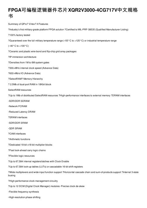
FPGA可编程逻辑器件芯⽚XQR2V3000-4CG717V中⽂规格书Summary of QPro? Virtex?-II FeaturesIndustry’s first military-grade platform FPGA solution Certified to MIL-PRF-38535 (Qualified Manufacturer Listing)100% factory testedGuaranteed over the full military temperature range (–55°C to +125°C) or industrial temperature range(–40°C to +100°C)Ceramic and plastic wire-bond and flip-chip grid array packagesIP-immersion architectureDensities from 1M to 6M system gates300+MHz internal clock speed (Advance Data)622+Mb/s I/O (Advance Data)SelectRAM Memory Hierarchy2.5Mb of dual-port RAM in 18Kbit blockSelectRAM resourcesUp to 1Mb of distributed SelectRAM resources High-performance interfaces to external memory DRAM interfaces-SDR/DDR SDRAM-Network FCRAM-Reduced Latency DRAMSRAM interfaces-SDR/DDR SRAM-QDR SRAMCAM interfacesArithmetic functionsDedicated 18-bit x18-bit multiplier blocksFast look-ahead carry logic chainsFlexible logic resourcesUp to 67,584 internal registers/latches with Clock EnableUp to 67,584 look-up tables (LUTs) or cascadable 16-bit shift registersWide multiplexers and wide-input function support Horizontal cascade chain and sum-of-products support Internal 3-state busingHigh-performance clock management circuitryUp to 12 DCM (Digital Clock Manager) modules -Precise clock de-skew-Flexible frequency synthesis-High-resolution phase shifting16 global clock multiplexer buffersActive interconnect technologyFourth-generation segmented routing structurePredictable, fast routing delay, independent offanoutSelectIO-Ultra TechnologyUp to 824 user I/Os19 single-ended and six differential standardsProgrammable sink current (2mA to 24mA) per I/ODigitally Controlled Impedance (DCI) I/O: on-chip termination resistors for single-ended I/O standards PCI compliant (32/33MHz) at 3.3VDifferential signaling622Mb/s Low-Voltage Differential Signaling I/O (LVDS) with current mode driversBus LVDS I/OLightning Data Transport (LDT) I/O with current driver buffersLow-Voltage Positive Emitter-Coupled Logic(LVPECL) I/OBuilt-in DDR input and output registersProprietary high-performance SelectLinkTechnology-High-bandwidth data path-Double Data Rate (DDR) link-Web-based HDL generation methodology ?Supported by Xilinx Foundation Series? and Alliance Series? Development SystemsIntegrated VHDL and Verilog design flowsCompilation of 10M system gates designsInternet Team Design (ITD) toolQPro Virtex-II 1.5V Platform FPGAsDS122 (v3.0) April 7, 2014Product SpecificationSlices LUTs Flip-FlopsMULT_ANDsArithmetic & Carry ChainsSOP Chains Distributed SelectRAM Shift Registers TBUF 488822128bits128bits2Table 17:Virtex-II Logic Resources Available in All CLBsDevice CLB Array: Row x Column Number of Slices Number of LUTs Max Distributed SelectRAM or Shift Register (bits) Number of Flip-Flops Number of Carry Chains (1)Number of SOP Chains (1)XQ2V100040 x 325,12010,240163,84010,2406480XQ2V300064 x 5614,33628,672458,75228,672112128XQ2V6000 96 x 8833,79267,5841,081,34467,584176192Each block SelectRAM cell is a fully synchronous memory, as illustrated in Table 31, page 38. The two ports have independent inputs and outputs and are independently clocked.Port Aspect RatiosT able 20 shows the depth and the width aspect ratios for the 18Kbit block SelectRAM. Virtex-II block SelectRAM also includes dedicated routing resources to provide an efficient interface with CLBs, block SelectRAM, and multipliers. Table 19:Dual-Port Mode ConfigurationsPort A 16K x 116K x 116K x 116K x 116K x 116K x 1Port B16K x 18K x 24K x 42K x 91K x 18512x 36Port A8K x 28K x 28K x 28K x 28K x 2Port B8K x 24K x 42K x 91K x 18512x 36Port A4K x 44K x 44K x 44K x 4Port B4K x 42K x 91K x 18512x 36Port A2K x 92K x 92K x 9Port B 2K x 91K x 18512x 36Port A 1K x 181K x 18Port B 1K x 18512x 36Port A 512x 36Port B512x 36Figure 31:18 Kbit Block SelectRAM in Dual-Port ModeTable 20:18Kbit Block SelectRAM Port Aspect RatioWidth Depth Address Bus Data Bus Parity Bus116,384ADDR[13:0]DA T A[0]N/A 28,192ADDR[12:0]DA TA[1:0]N/A 44,096ADDR[11:0]DA TA[3:0]N/A 92,048ADDR[10:0]DA TA[7:0]Parity[0]181,024ADDR[9:0]DA TA[15:0]Parity[1:0]36512ADDR[8:0]DA TA[31:0]Parity[3:0]。
- 1、下载文档前请自行甄别文档内容的完整性,平台不提供额外的编辑、内容补充、找答案等附加服务。
- 2、"仅部分预览"的文档,不可在线预览部分如存在完整性等问题,可反馈申请退款(可完整预览的文档不适用该条件!)。
- 3、如文档侵犯您的权益,请联系客服反馈,我们会尽快为您处理(人工客服工作时间:9:00-18:30)。
DS122 (v3.0) April 7, 2014 Product Specification
QPro Virtex-II 1.5V Platform FPGAs
DS122 (v3.0) April 7, 2014 Product Specification
QPro Virtex-II 1.5V Platform FPGAs
9
2,048
ADDR[10:0]
DATA[7:0]
18
1,024
ADDR[9:0]
DATA[15:0]
36
512
ADDR[8:0]
DATA[31:0]
Parity Bus N/A N/A N/A
Parity[0] Parity[1:0] Parity[3:0]
DS122 (v3.0) April 7, 2014 Product Specification
Port A
2K x 9
2K x 9
Port B
2K x 9
1K x 18
Port A
1K x 18
1K x 18
Port B
1K x 18
512 x 36
Port A
512 x 36
Port B
512 x 36
16K x 1 4K x 4 8K x 2 2K x 9 4K x 4 1K x 18 2K x 9 512 x 36
80
128
192
DS122 (v3.0) April 7, 2014 Product Specification
QPro Virtex-II 1.5V Platform FPGAs
DS122 (v3.0) April 7, 2014 Product Specification
QPro Virtex-II 1.5V Platform FPGAs
Device
CLB Array: Row x Column
Number of Slices
Number of
LUTs
Max Distributed SelectRAM or Shift
Register (bits)
XQ2V1000
40 x 32
5,120
10,240
163,840
XQ2V3000
64 x 56
16K x 1 2K x 9 8K x 2 1K x 18 4K x 4 512 x 36
16K x 1 1K x 18 8K x 2 512 x 36
16K x 1 512 x 36
X-Ref Target - Figure 31
18 Kbit Block SelectRAM
DIA DIPA ADDRA
Table 19: Dual-Port Mode Configurations
Port A
16K x 1
16K x 1
Port B
16K x 1
8K x 2
Port A
8K x 2
8K x 2
Port B
8K x 2
4K x 4
Port A
4K x 4
4K x 4
Port B
4K x 4
2K x 9
- QDR SRAM • CAM interfaces • Arithmetic functions • Dedicated 18-bit x 18-bit multiplier blocks • Fast look-ahead carry logic chains • Flexible logic resources • Up to 67,584 internal registers/latches with Clock Enable • Up to 67,584 look-up tables (LUTs) or cascadable 16bit shift registers • Wide multiplexers and wide-input function support • Horizontal cascade chain and sum-of-products support • Internal 3-state busing
• Ceramic and plastic wire-bond and flip-chip grid array packages
• Up to 12 DCM (Digital Clock Manager) modules - Precise clock de-skew - Flexible frequency synthesis - High-resolution phase shifting
• Low-Voltage Positive Emitter-Coupled Logic (LVPECL) I/O
• Built-in DDR input and output registers • Proprietary high-performance SelectLink
Technology - High-bandwidth data path - Double Data Rate (DDR) link - Web-based HDL generation methodology • Supported by Xilinx Foundation Series™ and Alliance Series™ Development Systems • Integrated VHDL and Verilog design flows • Compilation of 10M system gates designs • Internet Team Design (ITD) tool
14,336 28,67 88
33,792 67,584
1,081,344
Number of Flip-Flops
10,240 28,672 67,584
Number of Carry Chains(1)
64 112 176
Number of SOP
Chains (1)
WEA ENA SSRA
CLKA
DOA DOPA
DIB DIPB ADDRB WEB ENB SSRB
CLKB
DOB DOPB
DS031_11_071602
Figure 31: 18 Kbit Block SelectRAM in Dual-Port Mode
Port Aspect Ratios
Table 20 shows the depth and the width aspect ratios for the 18 Kbit block SelectRAM. Virtex-II block SelectRAM also includes dedicated routing resources to provide an efficient interface with CLBs, block SelectRAM, and multipliers.
• 16 global clock multiplexer buffers • Active interconnect technology
• Fourth-generation segmented routing structure
• IP-immersion architecture • Densities from 1M to 6M system gates • 300+ MHz internal clock speed (Advance Data) • 622+ Mb/s I/O (Advance Data)
Slices 4
LUTs 8
Flip-Flops 8
MULT_ANDs 8
Arithmetic & Carry Chains
2
SOP Chains
2
Distributed SelectRAM
128 bits
Shift Registers
128 bits
TBUF 2
Table 17: Virtex-II Logic Resources Available in All CLBs
• Predictable, fast routing delay, independent of fanout
• SelectIO™-Ultra Technology • Up to 824 user I/Os • 19 single-ended and six differential standards • Programmable sink current (2 mA to 24 mA) per I/O • Digitally Controlled Impedance (DCI) I/O: on-chip termination resistors for single-ended I/O standards • PCI compliant (32/33 MHz) at 3.3V • Differential signaling • 622 Mb/s Low-Voltage Differential Signaling I/O (LVDS) with current mode drivers • Bus LVDS I/O • Lightning Data Transport (LDT) I/O with current driver buffers
Table 20: 18 Kbit Block SelectRAM Port Aspect Ratio
Width
Depth
Address Bus
Data Bus
1
16,384
ADDR[13:0]
DATA[0]
2