
X96XX User Manual
Disclaimer: In the manual prepared by the process of the company have to content are correct and complete, if there are any errors or defects are not attached to any liability, the company reserves the right to change the specification may be mentioned without prior description of hardware and software. Thank you for using the company's products, please read carefully before using this manual. Due to failing to operating losses, the company will not be responsible for any economic responsibility and legal liability.
CONTENT Chapter 1 Product Introduction ..................................................................................................................................................................5 1.1 Introduction..............................................................................................................................................................................................5 1.2 Feature..................................................................................................................................................................................................... 5 Chapter 2 Device and accessories............................................................................................................................................................ 6 2.1 Button introduction on the front panel............................................................................................................................................... 6 2.2 Introduction for rear panel....................................................................................................................................................................7 2.3 Remote controller.................................................................................................................................................................................. 7 Chapter 3 Basic function operation.......................................................................................................................................................... 8 3.1 Navigation switch machine.................................................................................................................................................................. 8 3.2 login in...................................................................................................................................................................................................... 9 3.3 Menu Setting ........................................................................................................................................................................................ 10 3.3.1 Configuration management....................................................................................................................................................... 11 3.3.2 Data search .................................................................................................................................................................................. 28 3.3.3 Data Backup................................................................................................................................................................................. 29 3.3.4 Check information ....................................................................................................................................................................... 29 3.3.5 Disk management....................................................................................................................................................................... 30 3.3.6 Upgraded...................................................................................................................................................................................... 30 3.3.7 Logout user...................................................................................................................................................................................30 3.3.8 System turn off............................................................................................................................................................................. 30 3.3.9 System restart.............................................................................................................................................................................. 30 3.3.10 Exit............................................................................................................................................................................................... 30 Chapter 4 IE port operating instructions .............................................................................................................................................. 31 4.1 Main page of video monitoring ......................................................................................................................................................... 32 4.2 Stream selected................................................................................................................................................................................... 32 4.3 PTZ control........................................................................................................................................................................................... 32 4.4 Advanced setting box......................................................................................................................................................................... 33 Chapter 5 HDD installation........................................................................................................................................................................ 37 Guarantee ........................................................................................................................................................................................................ 38
最新Mc800系列说明书

智能多媒体控制系统Intelligent Multimedia Control SystemMC800系列用户手册User’s Manual1第一章前言....................................................................................................3第二章系统硬件安装......................................................................................42-1、系统设备的接口说明 ......................................................................42-2、系统设备的连接 ..............................................................................82-3、电动屏幕的连接........................................................................................ 8第三章系统软件安装....................................................................................93-1、安装视频捕捉卡及其软件 ..............................................................93-2、安装电脑控制软件设置 .............................................................. 10第四章系统通讯协议................................................................................ 19第五章系统备份与恢复............................................................................ 24第六章常见问题........................................................................................ 256-1. 按控制面板“系统开”无法开机 ................................................... 256-2. 红外学习不成功或显示成功却不能遥控.................................... 266-3. 有些设备红外遥控不灵 ............................................................... 266-4. 投影机切换不灵 ........................................................................... 266-5. 关投影机出问题 ........................................................................... 272第一章前言本手册说明了您所使用的智能多媒体控制系统(IMCS)的硬件和软件的安装和功能设置。
User Manual

USER MANUALmade late in the product’s development. All game art for this manual has been taken from the English version of this product.0434567New Game will allow you to create a single or multi-player game.• Hovering the curser over this button will show you more options.• Quick start will launch the game with your last New Game settings.• Beginner will start the game with pre-selected settings in order to give you theThe camera system allows you Zoom in and out by rotating the mouse wheel forward and126435 7231If you have an exploration ship on the star system you can launch an Expedition on this Curiosity to see what the planet is concealing.There are various types of Curiosities such as an anomalythat gives bonuses or penalties to a planet, a luxury orhave a ship equipped with Probes orbiting the system. Thenumber of probes is limited, and is replenished over timewhen they are used up. Each expedition costs one probe,and there are technologies to increase both the numberof probes the ship can carry and the speed of probereplenishment.The main quest is divided into several chapters which unlock as you complete the previous steps. There are also different branches and choices, allowing you to play and develop the civilization the way you want to—and then replay them for a different experience.SIDE QUESTS1243561. An overview of your empire, its type of government, and its various traits (bonuses / penalties).2. Your level of Approval at an empire level, calculated as the average of your star systems and their populations.3. A list of the colonized systems of your empire.3456789Each system line displays summary information related to its system:2. Status (Outpost or Colony, and the number of colonized planets)3. Population2456732131246753。
TCC89xx 91xx 92xx WinCE BSP User's Guide v1.3

TCC89xx/91xx/92xx WinCE BSP User's Guide September, 2009TelechipsWinCE BSP TeamCONTENTS1.Installation Sequence of WinCE6.0 development tool2.Make a New Project3.Building BSP Project4.How to burn ROM image files1. Installation Sequence of WinCE6.0 development tool•Step 1. Install “Visual Studio 2005”•Step 2. Install “Visual Studio 2005 SP1”•Step 3. Install “Windows Embedded CE 6.0 Platform Builder”•Step 4. Install “Windows Embedded CE 6.0 SP1 (required if PB 6.0 Tools have been installed)”•Step 5. Install “Windows Embedded CE 6.0 R2”–Link: /downloads/details.aspx?FamilyID=f41fc7c1-f0f4-4fd6-9366-b61e0ab59565&displaylang=en•Step 6. Install “Windows Embedded CE 6.0 Cumulative Product Update Rollup 12/31/2008”–Link: /downloads/details.aspx?FamilyID=b478949e-d020-465e-b451-73127b30b79f&DisplayLang=en•Step 7. Install QFE patches related exFAT.–QFE Monthly updated, January, 2009•/downloads/details.aspx?familyid=DDF5D4D2-6D3A-4695-B91D-7EEF5730B892&displaylang=en–QFE Monthly updated, June, 2009•/downloads/details.aspx?displaylang=en&FamilyID=fcdcedbd-3f80-4de6-9e88-ba7c5419b403–QFE Monthly updated, July, 2009•/downloads/details.aspx?displaylang=en&FamilyID=64bc9f44-e8ca-44f6-94e1-08206876ec23#tm•Step1. Copy BSP folder “Magellan”to “x:\WINCE600\PLATFORM\”–We do not provide msi file to install BSP•Step2. Menu File New Project•Step3. New Project DialogSelect Platform Builder for CE 6.0Create Name for new projectDon’t Check this option•Step4. OS Design WizardBoard Support Package:Check MAGELLAN BaseboardsDesign Template:Check TELECHIPS DEVICEDesign Template Variant:Check Telechips Multi-Media DeviceSelect Device Driver:Select Device DriversBacklight , Keypad, Serial, SDIO,VFPv2, USB(OTG Device), etc…OTG Host driver are not implemented yet Select Support Applications: Check COM, DCOM, SIP OpenGLES1.1/2.0•Step1. Modify “Magellan.bat”–Magallan.bat file is located in root directory of BSP project.@REM *************************************************************@REM *New Chip@REM *************************************************************set TCC_R_XX=0set TCC_R_AX=1@REM *************************************************************@REM *Display Setting @REM *RGB888 or RGB565 ex)set RGB888=1@REM *Display Height ex)set LCDHEIGHT=1E0@REM *Display Width ex)set LCDWIDTH=320@REM *************************************************************set RGB565=1set LCDHEIGHT=1E0set LCDWIDTH=320If version of TCC89xx/91xx/92xx is AX or AA, “setTCC_R_AX =1”should be activated.LCD Configuration-RGB format : RGB888 or RGB565-LCD Width and Height: Normally, Width = 800 / Height = 480@REM *************************************************************@REM *2D setting@REM *************************************************************set BSP_MAX_FGRP_EN=1F_GBUS Configuration-Set BUS clock of Graphic Block (Overlay Mixer, 3D) to Maximum.You can check the version of CHIP from silkscreen0AX/0AA indicates version ofCHIP1. Select Version of CHIP2. Configure LCD Settings3. Set Graphic BUS•Step1. Modify “Magellan.bat”–continue@REM *************************************************************@REM *Fmbus setting @REM *mDDR DRAM Type @REM *133Mhz :set BSP_FMBUS_133MHZ=1@REM *160Mhz :set BSP_FMBUS_160MHZ=1@REM *180Mhz :set BSP_FMBUS_180MHZ=1@REM *DDR2 DRAM Type @REM *280Mhz :set BSP_FMBUS_280MHZ=1@REM *330Mhz :set BSP_FMBUS_330MHZ=1@REM *360Mhz :set BSP_FMBUS_360MHZ=1 (Pair BSP_FCPU_720MHZ)@REM *400Mhz :set BSP_FMBUS_400MHZ=1@REM *************************************************************set BSP_FMBUS_280MHZ=1@REM *************************************************************@REM *Fcpu setting @REM *337Mhz :set BSP_FCPU_337MHZ=1@REM *506Mhz :set BSP_FCPU_506MHZ=1@REM *600Mhz :set BSP_FCPU_600MHZ=1@REM *720Mhz :set BSP_FCPU_720MHZ=1 (Pair BSP_FMBUS_360MHZ) @REM *************************************************************set BSP_FCPU_506MHZ=1Configure BUS clock. Followings are available BUS Clocks When Bootup-280MHz -330MHz -360MHz -400MHzConfigure CPU clock. Followings are available CPU ClocksWhen Bootup -337MHz -506MHz -600MHz -720MHz5. Select CPU Clock6. Select Memory BUS Clock•Step1. Modify “Magellan.bat”–continue@REM *************************************************************@REM *DDR2 DRAM Type@REM *@REM *CS BANK CAS_Latency CAS/RAS Size MaxClock PartNumber Vendor @REM *:set BSP_DRAM_TYPE1=1 : 1, 2, 5, 10/13 (16bit x 64 x 2) 128MB, 330Mhz K4T51163QG-HCE6(EVB 0.1) Samsung @REM *:set BSP_DRAM_TYPE2=1 : 1, 2, 6, 10/13 (16bit x 64 x 4) 128MB, 400Mhz H5PS5162FPR S2C-415A (EVB 1.0), HYNIX@REM * H5PS5162FFR S6C-915A HYNIX@REM *:set BSP_DRAM_TYPE3=1 : 1, 3, 5, 10/13 (16bit x 128 x 2) 256MB, 400Mhz K4T1G164QE-HCE7Samsung @REM * 330Mhz K4T1G164QQ-HCE6Samsung @REM *:set BSP_DRAM_TYPE4=1 : 1, 3, 6, 10/13 (16bit x 128 x 2) 256MB, 400Mhz K4T1G1643QG-HCF7Samsung @REM *: Test Only@REM *:set BSP_DRAM_TYPE5=1 : 1, 2, 5, 10/14 (8bit x 64 x 4) 256MB, 330Mhz E5108AG-6E-E ELPIDA @REM *:set BSP_DRAM_TYPE6=1 : 2, 2, 6, 10/13 (16bit x 64 x 4) 256MB, 400Mhz H5PS5162FFR S6C-915A HYNIX@REM *mDDR DRAM Type@REM *:set BSP_DRAM_TYPE7=1 : 1, 2, 3, 10/13 (16bit x 64 x 2) 128MB, 166Mhz H5MS516DFR J3M-919A HYNIX@REM *************************************************************set BSP_DRAM_TYPE3=1Configure DDR RAM type according to above reference table@REM ******** DDR Size Setting ******************IF "%BSP_DRAM_TYPE1%"=="1" set BSP_DRAM_SIZE_128=1 IF "%BSP_DRAM_TYPE2%"=="1" set BSP_DRAM_SIZE_128=1 IF "%BSP_DRAM_TYPE7%"=="1" set BSP_DRAM_SIZE_128=1 @REM ********************************************Size of DDR DRAM will be determined according to BSP_DRAM type automatically.7. Select Type of DDR Memory8. Select Size of DDR Memory•Step2. Modify “Magellan.bib”and “lcd.h”–Magallan.bib file is located in “Magellan\Files”.–You should modify SDRAM memory map according to your system specification.–Following figure shows relationship between magellan.bib and SDRAM memory map .#define SYSSTART 80000000#define SYSLEN 00200000#define NKSTART80200000IF BSP_DRAM_SIZE_128 ! ;256#define NKLEN02000000 ; 32MB #define RAMSTART 82200000#define RAMLEN 0A600000 ; 166MB #define DDRAWST 8C800000#define DDRAWLEN 01000000 ; 16MB #define HWSTART 8D800000#define HWLEN02800000 ; 40MB ELSE ;128MB#define NKLEN01A00000 ; 26MB #define RAMSTART 81C00000#define RAMLEN 04800000 ; 72MB #define DDRAWST 86400000#define DDRAWLEN 00800000 ; 8MB #define HWSTART 86C00000#define HWLEN01400000 ; 20MBENDIF0x800000000x8C800000BootLoader/Frame BufferKernel ImageSystem Free Memory Reserved MemoryFor 2D AccelReserved Memory For H/W Video CodecSYSSTARTNKSTART RAMSTARTDDRAWSTHWSTART HWLEN = 40MBDDRAWLEN = 16MBRAMLEN = 166MBNKLEN = 32MBSYSLEN = 2MB0x802000000x82200000#if defined(_DRAM_SIZE_128_)#define DISP_MEM_PHYBASE (0x46400000)#else#define DISP_MEM_PHYBASE (0x4C800000)#endifWINCE600\PLATFORM\Magellan\Files\Magallan.bibWINCE600\PLATFORM\Magellan\Src\BOOT\lcd.hFill Physical Address of “DDRAWST ”•Step2. Modify “Magellan.bib”–Memory Requirement•Required Memory For H/W Video Codec–HD 720p H.264»Level 4.1 : 20MByte»Level 5.1 : 46MByte–Full HD 1080p H.264»Level 4.1 : 40Mbyte»Level 5.1 : 96MByte•Required Memory For 2D Acceleration–It is dependent with LCD resolution»LCD resolution ≤800 x 480 8MByte is required»LCD resolution≥800 x 480 16MByte is required•Step3. Modify “lcd.h”to configure resolution of LCD #if defined(USE_LVDSLCD)#if defined(LVDS_CLAA104XA01CW_10_4_1024X768)#define DISP_WIDTH1024#define DISP_HEIGHT768#elif defined(LVDS_HT121WX2_103_12_1_1280X800)#define DISP_WIDTH1280#define DISP_HEIGHT800#endif#else#define DISP_WIDTH800 #define DISP_HEIGHT480 #endif Modify values of DISP_WIDTH, DISP_HEIGHT to same with values set on magellan.bat@REM *************************************************************@REM *Display Setting@REM *RGB888 or RGB565 ex)set RGB888=1@REM *Display Height ex)set LCDHEIGHT=1E0@REM *Display Width ex)set LCDWIDTH=320@REM *************************************************************set RGB565=1set LCDHEIGHT=1E0set LCDWIDTH=320•Step4. Select Catalog that you want to add•Step5. Select Solution configuration to MAGELLAN Baseboards Release•Step6. Execute Clean Sysgen when building firstly•Step1 Install VTC driver•Step2. Configure jumper of TCC89x EVB for FWDN Boot modeNAND Boot Mode (TNFTL V7)FWDN Boot Mode(TNFTL V7)•Step3. Execute FWDN program •Step4. Select ROM files•Catuion–From TCC89xx/91xx/92xx 0AX version, Only FWDN V2.00 can download ROM Images Caution:If tcBoot.rom was not selected, Write buttonof FWDN would not be activatied5. How to make SDK•After creating a custom OS design, SDK based on the OS design can be made according to following stepsStep1. Add New SDKStep2. Write down name of SDKStep3. Check MSI configurationStep4. Build SDKThank You。
STM32L496xx L4A6xx L4Rxxx L4Sxxx微控制器上 使用Chorm-ART

2018年8月DocID029937 Rev 1 [English Rev 2]1/22AN4943应用笔记在STM32L496xx/L4A6xx/L4Rxxx/L4Sxxx 微控制器上使用Chorm-ART Accelerator ™来刷新LCD-TFT 显示器前言本应用笔记旨在说明如何使用STM32L496xx/L4A6xx/L4Rxxx/L4Sxxx 微控制器上的Chrom-ART Accelerator™,通过FSMC 接口刷新LCD-TFT 显示屏。
STM32L496xx/L4A6xx/L4Rxxx/L4Sxxx 微控制器实现Chrom-Art Accelerator™ (DMA2D ),即专用于图像处理的专用DMA 。
它可以执行下列操作:•用特定颜色填充目标图像的一部分或全部•通过像素格式转换将源图像的一部分或全部复制到目标图像的一部分或全部中•将像素格式不同的两个源图像部分和/或全部混合,再将结果复制到颜色格式不同的部分或整个目标图像中。
在STM32L496xx/L4A6xx/L4Rxxx/L4Sxxx 微控制器上,使用灵活的静态存储控制器(FSMC )通过并行接口访问LCD-TFT 显示屏。
本应用笔记说明了以下内容:•如何通过FSMC 接口连接LCD-TFT 显示屏•如何为LCD-TFT 显示屏刷新配置DMA2D•如何使用DMA2D 字节重新排序功能直接驱动Intel 8080显示器。
要充分利用本应用笔记,用户应熟悉STM32 Chrom-ART Accelerator™(DMA2D ),如STM32L4x6基于Arm ®的高级32位MCU 参考手册(RM0351)和STM32L4Rxxx/L4Sxxx 基于Arm ®的高级32位MCU 参考手册(RM0432)中所述内容(可从意法半导体的网站 获取)。
表1. 适用产品类型产品线和部件号微控制器STM32L496AE 、STM32L496AG 、STM32L496QE 、STM32L496QG 、STM32L496RE 、STM32L496RG 、STM32L496VE 、STM32L496VG 、STM32L496ZE 、STM32L496ZGSTM32L4A6AG 、STM32L4A6QG 、STM32L4A6RG 、STM32L4A6VG 、STM32L4A6ZGSTM32L4R5/S5产品线,STM32L4R7/S7产品线,STM32L4R9/S9产品线目录AN4943目录1参考文档 . . . . . . . . . . . . . . . . . . . . . . . . . . . . . . . . . . . . . . . . . . . . . . . . . . . 52Chrom-ART Accelerator™(DMA2D)应用用例概述 . . . . . . . . . . . . . . . 63通过FSMC访问LCD-TFT显示屏 . . . . . . . . . . . . . . . . . . . . . . . . . . . . . . . . . 73.1硬件接口描述 . . . . . . . . . . . . . . . . . . . . . . . . . . . . . . . . . . . . . . . . . . . . . . . 73.2显示指令集(DCS)软件界面 . . . . . . . . . . . . . . . . . . . . . . . . . . . . . . . . . . 83.3通过STM32L496xx/L4A6xx/L4Rxxx/L4Sxxx微控制器控制D/CX信号 . . . . . 94STM32CubeL4中的Chrom-ART Accelerator™(DMA2D)配置 . . . . . . 114.1LCD部分刷新 . . . . . . . . . . . . . . . . . . . . . . . . . . . . . . . . . . . . . . . . . . . . . . .115新的DMA2D功能可支持Intel 8080显示器 . . . . . . . . . . . . . . . . . . . . . . . . . 135.1Intel 8080接口颜色编码 . . . . . . . . . . . . . . . . . . . . . . . . . . . . . . . . . . . . . . 135.2DMA2D重新排序功能 . . . . . . . . . . . . . . . . . . . . . . . . . . . . . . . . . . . . . . . . 165.2.1红蓝交换 . . . . . . . . . . . . . . . . . . . . . . . . . . . . . . . . . . . . . . . . . . . . . . . . 165.2.2字节交换 . . . . . . . . . . . . . . . . . . . . . . . . . . . . . . . . . . . . . . . . . . . . . . . . 165.3DMA2D重新排序用例示例 . . . . . . . . . . . . . . . . . . . . . . . . . . . . . . . . . . . . 175.3.116位FSMC数据总线接口上的24bpp/18bpp . . . . . . . . . . . . . . . . . . . . . . 175.3.28位FSMC数据总线接口上的24bpp/18bpp . . . . . . . . . . . . . . . . . . . . . . . 185.3.3通过8位FSMC数据总线接口的16bpp . . . . . . . . . . . . . . . . . . . . . . . . . . . 19 6结论 . . . . . . . . . . . . . . . . . . . . . . . . . . . . . . . . . . . . . . . . . . . . . . . . . . . . . . 20 7版本历史 . . . . . . . . . . . . . . . . . . . . . . . . . . . . . . . . . . . . . . . . . . . . . . . . . . 212/22DocID029937 Rev 1 [English Rev 2]AN4943表格索引表格索引表1.适用产品. . . . . . . . . . . . . . . . . . . . . . . . . . . . . . . . . . . . . . . . . . . . . . . . . . . . . . . . . . . . . . . . 1表2.FSMC 信号. . . . . . . . . . . . . . . . . . . . . . . . . . . . . . . . . . . . . . . . . . . . . . . . . . . . . . . . . . . . . . 7表3.LCD-TFT 信号. . . . . . . . . . . . . . . . . . . . . . . . . . . . . . . . . . . . . . . . . . . . . . . . . . . . . . . . . . . . 7表4.最小可使用FSMC地址位取决于图像大小(16位RGB565访问) . . . . . . . . . . . . . . . . . . . . 10表5.交换操作. . . . . . . . . . . . . . . . . . . . . . . . . . . . . . . . . . . . . . . . . . . . . . . . . . . . . . . . . . . . . . . 16表6.文档版本历史 . . . . . . . . . . . . . . . . . . . . . . . . . . . . . . . . . . . . . . . . . . . . . . . . . . . . . . . . . . . 21表7.中文文档版本历史. . . . . . . . . . . . . . . . . . . . . . . . . . . . . . . . . . . . . . . . . . . . . . . . . . . . . . . . 21DocID029937 Rev 1 [English Rev 2]3/22图片目录AN4943图片目录图1.显示应用典型用例. . . . . . . . . . . . . . . . . . . . . . . . . . . . . . . . . . . . . . . . . . . . . . . . . . . . . . . . . 6图2.显示总线接口规范. . . . . . . . . . . . . . . . . . . . . . . . . . . . . . . . . . . . . . . . . . . . . . . . . . . . . . . . . 8图3.用于LCD-TFT显示屏访问的存储器映射 . . . . . . . . . . . . . . . . . . . . . . . . . . . . . . . . . . . . . . . . 9图4.通过FSMC接口自动控制LCD-TFT显示屏数据/指令 . . . . . . . . . . . . . . . . . . . . . . . . . . . . . . 10图5.16位接口上的24bpp颜色编码. . . . . . . . . . . . . . . . . . . . . . . . . . . . . . . . . . . . . . . . . . . . . . . 14图6.8位接口上的16bpp颜色编码. . . . . . . . . . . . . . . . . . . . . . . . . . . . . . . . . . . . . . . . . . . . . . . . 15图7.8位接口上的24bpp颜色编码. . . . . . . . . . . . . . . . . . . . . . . . . . . . . . . . . . . . . . . . . . . . . . . . 15图8.支持16位接口上24bpp的DMA2D操作. . . . . . . . . . . . . . . . . . . . . . . . . . . . . . . . . . . . . . . . . 17图9.支持8位接口上24bpp的DMA2D操作. . . . . . . . . . . . . . . . . . . . . . . . . . . . . . . . . . . . . . . . . . 18图10.支持8位接口上16bpp的DMA2D操作. . . . . . . . . . . . . . . . . . . . . . . . . . . . . . . . . . . . . . . . . . 19 4/22DocID029937 Rev 1 [English Rev 2]AN4943参考文档1 参考文档以下文档可从获得。
ThreadXUserGuide-中文手册

常只要几个礼拜的时间。
非黑盒结构 ThreadX 的大部分包括完全的 C 源代码,这排除了许多商业性的内核结构所存在的“黑 盒”问题。在使用 ThreadX 时,程序开发者可以清楚的看到内核运行细节,不存在什么秘 密。 源代码还允许开发程序过程中特殊的修改。虽然没有介绍,但在十分必要时有能力去 修改内核是很有用的。 这些特色对那些习惯于用自己内部内核的开发者来说应该是特别另人振奋的。他们期 望得到源代码并且能够修改内核。ThreadX 对这些人来说是最合适的内核了。
■ 嵌入式应用程序 实时软件 多任务 任务及线程
■ ThreadX 的优点 改进的响应特性 软件维护 增强的吞吐量 处理器隔离 程序划分 好用性 提高开发时间 保护软件投资
ThreadX 概 述
ThreadX 概述
ThreadX 是专为嵌入式应用而设计的高性能实时内核。同其它实时内核不同,ThreadX 具有通用性,使基于 RISC(reduced instruction set computer 简化指令集计算机)和 DSP(Digital Signal Processing 数字信号处理)的小型微控制器的应用程序易于升级。
手册概述
本手册提供了有关 ThreadX——Express Logic 公司高性能实时内核的详尽信息。
指南之意义 本手册适用于嵌入式实时软件的开发者。开发者应熟悉标准实时操作系统的功能及 C
程序设计。
结构 手册包括七章,五个附录以及一篇索引。各部分大致介绍如下: 第一章 ThreadX 概述及其与嵌入式实时系统的关系。 第二章 安装步骤及使用事项。 第三章 详细介绍高性能实时内核——ThreadX 的功能操作。 第四章 详细介绍 ThreadX 应用程序的接口。 第五章 介绍 ThreadX 应用程序的写 I/O 驱动程序。 第六章 ThreadX 处理器自带示例程序的介绍。 第七章 ThreadX 的内部结构。 附录 A ThreadX API 附录 B ThreadX 常量 附录 C ThreadX 数据类型 附录 D Thread 源程序 附录 E ASCII 代码表
ultra96 入门指南说明书
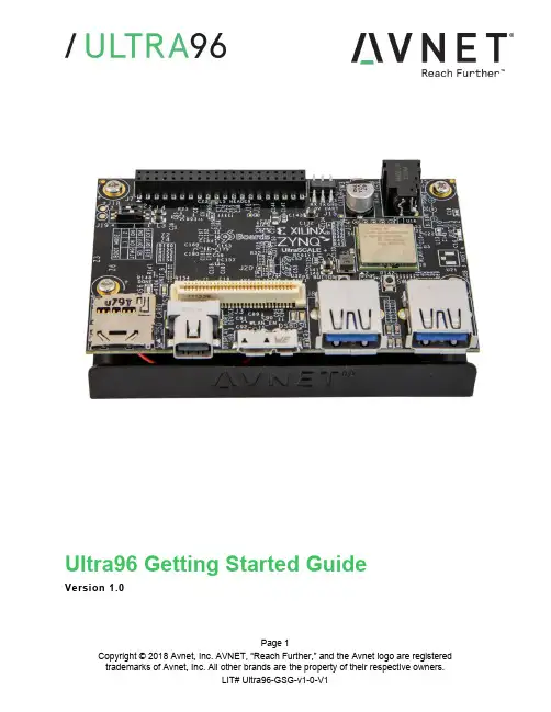
Page 1Ultra96 Getting Started GuideVersion 1.0Document ControlDocument Version: 1.0Document Date:27 June 2018Page 2Contents1Getting Started with Ultra96 (5)2What’s Inside the Box? (5)2.1Optional add-on items: (5)3What’s on the Web? (6)3.1Official Documentation: (6)3.2Tutorials and Reference Designs: (6)3.3Trainings and Videos: (6)4Ultra96 Key Features (7)5Ultra96 Basic Setup and Operation (9)6Example Design (10)7Hardware Setup (10)8Connect to Webserver (11)9Ultra96 GPIO LEDs Example Project (13)10OpenAMP Matrix Multiplication (14)11Additional Example Projects (14)12Custom Content Tutorial (15)13Smart Tutorial (16)14Using Ultra96 Tutorial (16)15Access Ultra96 Linux Terminal over SSH (17)16INA226 Current Sensor (19)17Power Off (20)18Getting Help and Support (21)18.1Avnet Support (21)18.2Xilinx Support (22)19Installing and Licensing Xilinx Software (23)19.1Install Vivado Design Suite, Design Edition (23)20Certification Disclaimer (27)21Safety Warnings (27)22RF Certification (27)Page 3FiguresFigure 1 – Ultra96 (5)Figure 2 – Ultra96 Block Diagram (8)Figure 3 – Ultra96 Topology (9)Figure 4 – Ultra96 Switch Location (10)Figure 5 – MicroSD Card Boot Mode (11)Figure 6 – Connect to Ultra96 Webserver (12)Figure 7 – Ultra96 GPIO LEDs (13)Figure 8 – OpenAMP Matrix Multiplication (14)Figure 9 – Ultra96 Tutorials/Guides (15)Figure 10 – TeraTerm New Connection (17)Figure 11 – SSH Terminal Settings (18)Figure 12 – SSH Authentication (18)Figure 13 – Ultra96 Terminal (19)Figure 14 – I2Cdetect (19)Figure 15 – Reading INA226 Device (20)Figure 16 – Voucher Confirmation (24)Figure 17 – Generate Node-Locked (24)Figure 18 – Select Host Information (25)Page 4Page 5 1 Getting Started with Ultra96The Avnet Ultra96 enables hardware and software developers to explore the capabilities of the Zynq® UltraScale+™ MPSoC . Designers can create or evaluate designs for both the Zynq Processor Subsystem (PS) and the Programmable Logic (PL) fabric.Figure 1 – Ultra96This Getting Started Guide will outline the steps to setup the Ultra96 hardware. It documents the procedure to run a PetaLinux design running on the Quad-core ARM Cortex-A53 MPCore Processing System (PS).2 What’s Inside the Box?∙Ultra96 development board ∙Pre-programmed 16GB microSD card with SD adapter and jewel case ∙Voucher for SDSoC license from Xilinx ∙Quick Start Instruction card 2.1 Optional add-on items: ∙External 96Boards compliant power supply kit (12V, 2A, US plug) (AES-ACC-U96-PWR) ∙USB-to-JTAG/UART pod for Ultra96 (AES-ACC-U96-JTAG) ∙∙3 What’s on the Web?Ultra96 is a community-oriented kit, with all materials being made available through the community website.3.1 Official Documentation:∙Getting started guide∙Hardware user guide∙Schematics∙Bill of materials∙Layout∙PCB net lengths∙Mechanical drawing∙3D Model∙Board definition files for Vivado integration∙Programmable logic (PL) master user constraints3.2 Tutorials and Reference Designs:∙Ultra96 Bare Metal Hardware Platform Creation∙Ultra96 Bare Metal Microchip USB-UART∙Ultra96 Bare Metal Test Application Development∙Ultra96 Bare Metal Boot Techniques∙Ultra 96 Factory Restore Image∙Ultra96 Accelerated Image Classification3.3 Trainings and Videos:∙Introduction to Ultra96Page 64 Ultra96 Key Features∙Zynq UltraScale+ MPSoC ZU3EG SBVA484∙Memoryo Micron 2 GB (512M x32) LPDDR4 Memoryo MiroSD SocketShips with Delkin Utility MLC 16GB card∙ Wi-Fi / Bluetooth∙ DisplayPort∙ 1x USB 3.0 Type Micro-B upstream port∙ 2x USB 3.0 Type A downstream ports∙ 40-pin Low-speed expansion header∙ 60-pin High speed expansion header∙ Mounted on thermal bracket with fanNote that there is no on-board, wired Ethernet interface. All communications must be done via USB, Wi-Fi, JTAG, or expansion interface.Page 7Page 9 5 Ultra96 Basic Setup and OperationThe functionality of the Ultra96 is determined by the application booted from the non-volatile memory – by default that is the SD Card. This Getting Started Guide allows system developers to exercise and demonstrate multiple circuits through PetaLinux, including:∙SSH Terminal Access ∙GPIO LEDs ∙Wi-Fi ∙ I2C Sensor DetectIn addition to the items included in the kit, you will also need the following to complete the exercises in this tutorial.∙ Wi-Fi connectionAn Ultra96 image in its expected out-of-box configuration is shown below along with various topology components highlighted.Figure 3 –Ultra96 Topology6 Example DesignThe Ultra96 ships with an example image loaded in the 16GB microSD Card. If your microSD Card image has been corrupted or deleted, there is Ultra 96 Factory Restore available at that will go into detail on how to restore your factory image.7 Hardware Setup1. A terminal program is required. TeraTerm was used in this example which can bedownloaded from the TeraTerm project on the SourceForge Japan page:ttssh2.sourceforge.jp Install TeraTerm or another terminal program of your choice.2. Plug in your 12V Barrel Jack power supply into a wall outlet and then connect the barreljack to J5 on your Ultra96. Your Ultra96 should be powered down at this point. Note: DC power supply is not included in the Ultra96 kit but can be purchased separately.3. Set the Ultra96 boot mode switch SW2 to SD Card boot mode as shown below.Figure 4 – Ultra96 Switch LocationPage 108 Connect to Webserver1. Press and release the power button (SW3). The Green Power On LED (DS9), RedINIT_B LED (DS7) and the Green User LEDs should illuminate. After a few seconds, INIT_B LED will turn off and the Green DONE LED (DS6) will illuminate. At 15 seconds, the Blue Bluetooth Enable LED (DS1) will illuminate. At 30 seconds, the Yellow Wireless LAN Enable LED (DS8) will illuminate.2. After about 40 seconds, a new Wi-Fi SSID will be discoverable, named“Ultra96_<MAC_ID>” which is unique for each board. Connect the Wi-Fi on your PC to this SSID.Page 11Figure 6 – Connect to Ultra96 Webserver3. Now that we are connected to the Ultra96, we should open up the webserver. Open aninternet browser window and navigate to the following address : http://192.168.2.14. You will be directed to the webserver’s home page for Ultra96. Here you will be able toview example projects, custom contents and various tutorials for Ultra96.Page 129 Ultra96 GPIO LEDs Example Project1. Next we want to access the Ultra96 GPIO LEDs example project. From the Ultra96 homepage select Ultra96 GPIO LEDs example projectFigure 7 – Ultra96 GPIO LEDs2. All LEDs will be at an unknown state to begin with. Select the drop down menus andbegin changing the status of the GPIO LEDs. You will notice that the four LEDs (located in between the two USB connectors J8/J9) update in real time.3. Scroll to the bottom of the webpage and you will see a definition table for various LEDselection options.4. Something of interest may be setting LEDs 0 and LEDs 1 to phy0tx and phy0rxrespectively.5. Now as you navigate throughout this webserver you will notice the Wi-Fi transmitting andreceiving LEDs flickering as you are sending and receiving data from the Ultra96.Page 1310 OpenAMP Matrix Multiplication1. Select Example Projects up at the top of the page. You will see a list of projects alongwith descriptions of each.2. Select OpenAMP Matrix Multiplication which is the second in the list.Figure 8 – OpenAMP Matrix Multiplication3. Read through the description which goes over what is going to happen in the OpenAMPMatrix Multiplication Design and then select Run Project4. In the Output section you will see the two input matrices and then the matrix multiplicationresults.11 Additional Example Projects1. Return back to the Example Projects page by selecting the Example Project tab at thetop.2. As you can see there are seven additional example projects available to you. Feel freeto explore them. However some require additional hardware such as the Grove Starter Kit to complete.Page 1412 Custom Content Tutorial1. Now select the Tutorial tab at the top of the page. You will be directed to aTutorials/Guides pageFigure 9 – Ultra96 Tutorials/Guides2. This sections goes into how to get started with the out of box microSD card image wehave been exploring up to this point. As of now we have explored the Run Example Projects section.3. Let’s take a look at the Custom Content tutorial. Select Custom Content.4. This Tutorial goes over the three different ways custom content can be added to this outof box image. The three different ways being1) Uploading custom files2) Making custom webpages3) Making custom projects5. To access these options select the Custom Content tab at the top of the webpage.Page 1513 Smart Tutorial1. Now return back to the Ultra96 Tutorials page. This time select Smart from the tutoriallist2. This tutorial goes into explaining how to use the Smart Package Manager (smart) toupdate/install packages.3. This tutorial also provides an example that you can follow along with that will showcasea use case of how to write a simple “Hello World” application, compile it, create a RPMpackage with CMake, install/remove it with smart, and then run it.14 Using Ultra96 Tutorial1. Return back to the Tutorials page and now select the Using Ultra96 tutorial2. This tutorial goes over the various ways you can interact with the Ultra96. As of now wehave only done this using the Webapp.3. We will not be exploring accessing your Ultra96 over miniDP or UART since by defaultyou would need additional hardware to access it through these two peripherals.4. Read through the SSH section, it states we can access the Ultra96 terminal usingTeraTerm or a PuTTY terminal application.5. Since we have already downloaded and installed TeraTerm at the beginning of this guidelet’s access the Ultra96’s Linux terminal over SSH using TeraTermPage 1615 Access Ultra96 Linux Terminal over SSH1. Verify that your PC is still connected to the Ultra96 Websever by checking your wirelessnetwork.2. Open TeraTerm and then select File New connection… as seen in the image below.Figure 10 – TeraTerm New ConnectionPage 17Page 183. A new TeraTerm: New connection window will open. We now want to connect to Ultra96over SSH, select TCP/IP and then configure your Terminal settings the same as the below figure.Figure 11 – SSH Terminal Settings4. Select OK5. You will then be prompted to enter SSH Authentication information. In our case it islooking for the Linux terminal ’s user name and passphrase which are root and root .6. Please type in root for the User name and then type in root for the Passphrase as well.Then select OK .Figure 12 –SSH Authentication7. You now have access to the Ultra96 Terminal!Figure 13 – Ultra96 Terminal16 INA226 Current Sensor1. Now that we have access to the Linux Terminal let’s try and read from the INA226 CurrentSensor on our board.2. Type in your console i2cdetect –y –r 1Figure 14 – I2Cdetect3. As you can see some devices are coming back as unavailable under I2C detect, thismeans they may already be monitored by some other driver within the system. That is the case for the INA226 Current Sensor on Ultra964. It turns out there is a Linux sysfs drive for INAxxx devices that is already built into thekernel:Page 19https:///pub/scm/linux/kernel/git/torvalds/linux.git/tree/Documentation/hwmon/ina2xx5. Based on this it turns out that you can actually just read the system current from theINA226 device by using the sensor command.6. In your terminal type sensorsFigure 15 – Reading INA226 Device7. As you can see the current, voltage, and temperature measurements are reported back.8. This is one of the lesser known but highly useful Linux subsystems.17 Power Off1. When you are done experimenting with your Ultra96 and wish to power off the board,press and release the Power button (SW3) located on the top side of your Ultra96 next to the barrel jack.2. You will notice your board does not power down immediately. It will take roughly 10-20seconds for your board to completely power down. The reason behind this is it is adhering to the various power down sequencing requirements.3. Please note, if you do not let your Ultra96 power off as per the power down sequencingrequirements (such as unplugging the barrel jack), your SD Card may get corrupted or damaged.4. To power off the Ultra96 you can also press and hold Sw3 for 10 seconds to force apower off. This is useful for when the soft power-off appears to no work.Page 2018 Getting Help and Support18.1 Avnet SupportThe Ultra96 is a versatile development kit that allows evaluation of the Zynq MPSoC, which can help you adopt Zynq into your next design. All technical support is offered through website support forums. Ultra96 users are encouraged to participate in the forums and offer help to others when possible./forums/zed-english-forumTo access the most current collateral for Ultra96 please visit the community support page at: /content/support –Hardware/Vivado Support–Software SupportOnce on the support page:To access the latest Ultra96 documentation, click on the Documentation link:To access the latest reference designs for Ultra96, click on the following link:To access the Ultra96 technical forums, click on the following link:Page 21To view online training and videos, click on the following link:18.2 Xilinx SupportFor questions regarding products within the Product Entitlement Account, visit the Contact Support site for Xilinx:https:///support/service-portal/contact-support.htmlFor technical support including the installation and use of the product license file, contact Xilinx Online Technical Support at /support. The following assistance resources are also available on the website:∙Software, IP and documentation updates∙Access to technical support web tools∙Searchable answer database with over 4,000 solutions∙User forumsPage 2219 Installing and Licensing Xilinx Software19.1 Install Vivado Design Suite, Design EditionThe Zynq device on the Ultra96 is supported in Vivado Design Suite, Design Edition. Version 2018.1 or later is required to use the pre-installed board definition file.You must license your Vivado Design Suite, Design Edition with the license that came with your Ultra96. To obtain your free license, visit the following website and insert the voucher code from the certificate included in your kit:/getlicense1. Log in2. Fill out information at Product Licensing - Name and Address Verification, then clickNext3. Select your Account4. Enter your voucher code here, then click Redeem Now.Page 235. At the confirmation screen, click Yes.Figure 16 – Voucher Confirmation6. Under Certificate Based Licenses, find OEM Zynq ZU3 Ultra96 Vivado Design EditionVoucher pack and check the box. Now click Generate Node-Locked License.Figure 17 – Generate Node-LockedPage 247. Create or select your Host ID. Click Next.Figure 18 – Select Host InformationPage 258. Review the license request, then click Next again.If a full seat of Vivado System or Design Edition has already been installed, then no further software will be needed. Please check online for any updates at:/support/download/index.htmFor detailed instructions on installing and licensing the Xilinx tools, please refer to the latest version of Vivado Design Suite User Guide Release Notes, Installation, and Licensing (UG973).Page 2620 Certification DisclaimerBoth CE and FCC certifications are necessary for system level products in those countries governed by these regulatory bodies.Because Avnet boards are intended for evaluation kits only and destined for professionals (you) to be used solely at research and development facilities for such purposes, they are considered exempt from the EU product directives and normally are not tested for CE or FCC compliance.If you choose to use your board to transmit using an antenna, it is your responsibility to make sure that you are in compliance with all laws for the country, frequency, and power levels in which the device is used. Additionally, some countries regulate reception in certain frequency bands. Again, it is the responsibility of the user to maintain compliance with all local laws and regulations.This board should be used in a controlled lab environment by professional developers for prototype and development purposes only. The board included in the kit is not intended for production use unless additional end product testing and certification is performed.21 Safety WarningsThis product shall only be connected to an external power supply that is 96boards compliant.Only compatible plug-in modules shall be connected to Ultra96. The connection of incompatible devices may affect compliance or result in damage to the unit and void the warranty.This product shall be operated in a well-ventilated environment. If a case is used, it shall have adequate ventilation.22 RF CertificationThe frequency range is 2.4 to 2.4835GHz.The max power complies with 802.11b, which is 17dBm (typ).More information on RF certification for the TI WiLink8 module is available here:/index.php/WL18xxMOD_Regulatory_Product_Certification#Countri es_Accepting_FCC.2FIC.2FCE.2FMIC_ReportsPage 27。
PLX SDK User Manual
User’s Manual
Version 4.40 March 2006
© 2006, PLX Technology, Inc. All rights reserved.
PLX Technology, Inc. retains the right to make changes to this product at any time, without notice. Products may have minor variations to this publication. PLX assumes no liability whatsoever, including infringement of any patent or copyright, for sale and use of PLX products.
PLX Technology and the PLX logo are registered trademarks of PLX Technology, Inc.
Other brands and names are the property of their respective owners.
PLX SOFTWARE LICENSE AGREEMENT
LICENSE Copyright © 2006 PLX Technology,
Inc.
This PLX Software License agreement is a legal agreement between you and PLX Technology, Inc. for the PLX Software, which is provided on the enclosed PLX CD-ROM. PLX Technology owns this PLX Software. The PLX Software is protected by copyright laws and international copyright treaties, as well as other intellectual property laws and treaties, and is licensed, not sold. If you are a rightful possessor of the PLX Software, PLX grants you a license to use the PLX Software as part of or in conjunction with a PLX chip on a per project basis. PLX grants this permission provided that the above copyright notice appears in all copies and derivatives of the PLX Software. Use of any supplied runtime object modules or derivatives from the included source code in any product without a PLX Technology, Inc. chip is strictly prohibited. You obtain no rights other than those granted to you under this license. You may copy the PLX Software for backup or archival purposes. You are not authorized to use, merge, copy, display, adapt, modify, execute, distribute or transfer, reverse assemble, reverse compile, decode, or translate the PLX Software except to the extent permitted by law.
TrueSecure TM GTU Series Fingerprint Module User M
TrueSecure TMGTU Series Fingerprint ModuleUser Manual���� 10� �01�Revision: V1.00 Date: ���� 10� �01�Table of ContentsTable of Contents1 Introduction .............................................................................................................32 Functional Description . (3)View Image (5)Enro�� (6)Verif� (7)Identif� (8)Se�ect User (9)De�ete User ..........................................................................................................................10Save Image ..........................................................................................................................10View Log (10)Settings (11)Simi�arit� Thresho�d .............................................................................................................11Exit (11)Introduction1 IntroductionThis demonstration program is a simple but helpful program that will assist users to becomefamiliar with the features of the GTU series of fingerprint modules. The program allows easyimplementat of all the major functions required for fingerprint recognition.2 Functional DescriptionAfter program installation, execute the program by double-clicking on the Gingy_Demo.exe in theSDK program directory. After execution the following start up screen will be displayed.The program includes the following fingerprint recognition functions:Functional DescriptionThis start up screen contains a set of fingerprint module functions which are described in thefollowing section.Functional Description View ImageThe View Image can be selected to view the recorded fingerprint image. This function is used toadjust the image quality for the CMOS optical device. As the default settings may be not suitablefor certain environment or finger types, the user can adjust the brightness, contrast and gamma toget a satisfactory image quality for later enrollment or authentication.Functional DescriptionEnrollThe Enroll function is used to enroll a new fingerprint as the current user. At least three fingerprints are required to complete the enrollment. Place the finger on the reader for at least three times until the enrolled quality is displayed.The fingerprint reader will take the common features of these fingerprints and after a few seconds of processing, the reader will inform the user of the enrolment result.The following table shows the five levels of quality that are provided.You can Select Enroll to enter the enrollment mode. The screen is the same as the snap function. After enrolling a fingerprint successfully, a dialog box will appear which shows the enrolled quality. The user is now requested to input a name and choose the enrolled finger. After inputtingthe desired data, select “Save” to save the data.Functional Description VerifyThe Verify function is used to check a live-scanned fingerprint from the current user. It implementsonly a one-to-one matching. The matching compares a live-scanned fingerprint image against apreviously enrolled fingerprint image, to verify that they came from the same finger. To use thisfunction place a finger on the reader and the fingerprint reader will check it out automaticallyaccording to the security level settings.The objects to be compared are the live-scanned fingerprint image and the final fingerprinttemplate - EnrlTemplate, which is the data that was saved during enrollment. After a successfulsnapping, the live-scan fingerprint image data is stored in the main memory. The EnrlTemplate canbe chosen by clicking Select User or by creating a new user through the enrollment process.The Verify function can be selected to enter the matching fingerprint mode. Before clicking theVerify button, a user must first be selected, otherwise the following screen will appear.After verification, the result will be displayed on the screen to show if the verification achieved amatch or if it failed. See Identify for details.Functional DescriptionIdentifyThe Identify function is used to identify a live-scanned fingerprint image from the database. This function implements a one-to-many matching. The matching process compares a live-scanned fingerprint image with a previously enrolled database. To use this, a finger should be placed upon the reader to allow the fingerprint reader to check it out automatically according to the security level settings.The Identify function can be selected to enter the matching fingerprint mode. After identification, the result will be displayed on the screen to show if the identification has achieved a match or if ithas failed. If the identification is successful the user information will also be shown on the screen.Functional Description Select UserThe Select User function is used to select a User for verification. The user data files are createdafter enrollment. Once a user has been selected, it will become the target for verification. The nameof the user will be displayed on the demo program screen.There are two methods to change the target that is to be verified:▆Select another user from the function of Select User.▆After enrollment, the enrolled user will become the new matching target automatically.The Select User can be selected to enter the Select User mode. The following screen will appearshowing the user list, containing the name, enrolled finger and enrolled class. To select a user,choose the user and click the “OK” button or double-click on the desired user.Functional Description Delete UserThe Delete User function will delete a User from the database. Once you have selected a user, the user will be deleted from the list.Save ImageThe Save Image function is used to save the fingerprint image to a file. After a successful fingerprint snap operation, the fingerprint image will be stored in the main memory. A fingerprint image can be saved using this function. Select the Save Image function to enter the Save Image mode. Select a specified folder and input the filename.According to the user’s requirements, there are two file types that can be selected:▆File TypeBMP: Save the fingerprint image in bitmap file format.View LogThe View Log is used to view the operation history. The log can be sorted by “Date”, “Name” or“Action” by clicking the relative radio buttons. See the dialog box below.Functional DescriptionSettingsSecurity LevelThe default security level is Medium. Set up the security level for matching by setting the verification threshold. High is the safest mode, providing a FAR of less than 1/100,000. Fair is a less tight mode, providing a FAR of less than 1/1000.DeviceSelect a device for the system.Enroll ModeSelect an enrolled mode for the enrollment. All three modes will give high matching performances. However, larger template sizes will require the storage of more fingerprint data, giving higher accuracy but lower speed. The user may use the different modes depending upon their applications.For smaller capture device areas or 1-1 verification or 1-few identifications, the 504-byte mode is recommended. Where it is required to identify a large number of fingerprints, then speed may be the main concern and subsequently the 168-byte or 336-byte mode is recommended.Similarity ThresholdThe Similarity Threshold function is used to adjust the Security Level. The higher the Similarity Threshold, the higher the security levels. However higher security levels will also result in enrollment difficulties.ExitThe Exit function is used to terminate the demo program.Functional DescriptionCopyright© �01� b� HOLTEK SEMICONDUCTOR INC.The information appearing in this Data Sheet is believed to be accurate at the timeof publication. However, Holtek assumes no responsibility arising from the use ofthe specifications described. The applications mentioned herein are used solely forthe purpose of illustration and Holtek makes no warranty or representation that such applications will be suitable without further modification, nor recommends the use ofits products for application that may present a risk to human life due to malfunction or otherwise. Holtek's products are not authorized for use as critical components in lifesupport devices or systems. Holtek reserves the right to alter its products without prior notification. For the most up-to-date information, please visit our web site at http://www.ho�.Note that Holtek’s fingerprint recognition products have been designed in conjunction withGing� T echno�og�.。
HE17x Series USB Data Logger User Manual
1HE17x SeriesUSB Data Logger UserManualCONTENTSB Data Logger Hardware (3)1.1Introduction (3)1.2Features (3)1.3Application (3)1.4USB Data Logger Model (3)1.5USB Temperature Data Logger Appearance(HE170/HE171/HE172) (4)1.6USB Temperature Data Logger Screen(HE170/HE171/HE172) (4)1.7USB Temperature&Humidity Data Logger Appearance(HE173/HE174) (5)1.8USB Temperature&Humidity Data Logger Screen(HE173/HE174) (5)1.9Button (6)1.10Install Battery (6)1.11Fix USB Data Logger (6)Chapter2.Logpro Software (7)2.1The Requirement of the Computer Hardware (7)2.2Install Driver&Software (7)2.3Setting the logger’s properties to start a new measurement (8)2.4Properties Description (9)2.5Start record time description (10)2.6Download the Records after a Measurement (10)2.7Data Listing Window (12)2.8Exporting Logs from Logpro (12)2.9Delete Records in the Logger (13)2.10Check the Save File in File List (13)Chapter3.Attention (14)Chapter4.FAQ (14)4.1LCD Screen Dim (14)4.2Data&Time Error (14)4.3Software"Runtime Error" (14)4.4Check COM Port Number (14)B Data Logger Hardware1.1IntroductionHE170USB series has USB interface,enjoying elegant appearance and compact construction,specially designed for refrigerator and cold-chain transportation as well as container transport applications.HE170USB series adopts friendly USB interface,friendly mounting bracket and the screws.HE170USB series can show temperature/temperature and humidity simultaneously as well as the battery indication.The OK key can help to check the Max/Min/Current value and the upper and lower limits.1.2Features⏹Waterproof and dustproof standard IP67,resisting moisture and dust.⏹Can set temperature and humidity limit value and LED lights will flash when the valuebeing exceeded.⏹Lower consumption design,1/2AA3.6V Lithium battery,working for12months and easyto replace.(Logging Interval:600s)⏹Transfer logging data to PC through software and can be saved as different types toensure the existence.⏹Use high sensitivity sensor,fast reaction and high precision.⏹Size(L x H x D):126mm x34mm x28mm1.3ApplicationWildly use in cold chain Transportation,Containers.1.4USB Data Logger Model1.5USB Temperature Data Logger Appearance(HE170/HE171/HE172)8①LCD Screen⑥Battery Replacement Position.②Button⑦Waterproof Transparent Cover③LED Warming Light When the⑧Fixed BracketTemperature Value Exceeds SettingLimits.④USB Connection Port⑨Model Label⑤Waterproof Ring1.6USB Temperature Data Logger Screen(HE170/HE171/HE172)①Display the High Limit⑤Display the Maximum Value inRecords②Display the Low Limit⑥symbol display shows being thelogging status.③Battery power indication.⑦Temperature Value④Display the Minimum Value in⑧Temperature Unit(℃or℉)Records1.7USB Temperature&Humidity Data Logger Appearance(HE173/HE174)8①LCD Screen⑥Battery Replacement Position.②Button⑦Waterproof Transparent Cover③LED Warming light When the⑧Fixed BracketTemperature or Humidity ValueExceeds the Setting Limits.④USB Connection Port⑨Model Label⑤Waterproof Ring1.8USB Temperature&Humidity Data Logger Screen(HE173/HE174)①Display the High Limit⑤Battery power indication.②Display the Low Limit⑥Units symbol display℃or℉,%RH③Display the Maximum Value in⑦ValueRecords④Display the Minimum Value inRecords1.9ButtonOK Button1.Press this button for long to 5seconds can turn on/off the logger.2.Check the MAX;MIN;High &Low values as well as the current value in the working status.1.10Install Battery1.Open the Battery Cover2.Remove shell3.Install Battery1.11Fix USB Data Loggere Screw to Fix the Bracket onto the Wall.2.Install the Data Logger.Chapter 2.Logpro Software2.1The Requirement of the Computer Hardware1.OS:Windows2000/XP/Vista/Win7/Win8/Win10(32/64-bit ),nonsupport Linux/UnixOS.2.CPU:1.6GHz3.Physical Memory:512MB4.Hard-drive Space:4GBB Port:12.2Install Driver &Software1.Install DriverPut the assigned software disc into the computer driver and open the file tofindand select the driver based on the operating system.OS Win7/Win8/Win10-64select “CH341SER[64bit]”.OS Win XP;Vista;Win7-32select “CH341SER[32bit]”(1)Click 【CH341SER 】;(2)Click 【INSTALL 】—【Confirm】2.Install Logpro SoftwareNotice:Please Install Logpro Software inD:\2.3Setting the logger’s properties to start a new measurement.1.Connect the data logger to the computer.12.Running Logpro software on the PC.3.From the toolbar select Connect.24.Read the logger’s properties.5.Set the properties.6.Sync the properties &time.(The PC time will be synchronized to the logger as well.)7.From the toolbar select Disconnect8.Unplug the logger from the Computer,and then the logger is in Standby mode 3.9.Press OK button on the logger,turn on the Data Logger and start recording.1The windows operating system cannot handle USB devices being unplugged and plugged back too fast.When unplugging the logger,wait for about 5seconds before plugging it in again.If you unplug and plug back a device too quickly,the computer may stop recognizing any USB devices on that port.If this happens you will have to restart the computer.This is a windows USB problem and is not related to Logpro.2If more than one logger is connected to your computer at the same time,the program will ask you to choose COM port manually.3The logger has three modes:1.LOG:In the mode,the logger samples and records data timely.2.Standby:In the mode,the logger stops to sample and record,and the LCD display is OFF.3.OFF:In the mode,the logger stops to sample and record,and the LCD display is off.Logpro cannot connect to the logger also.654732.4Properties DescriptionProperty Text DescriptionName English letters orNumbersName of the loggerSN10Characters Must be the same as the one in the label oflogger.Sampling Interval(s)Number from1to240Sampling frequency in LCD screenLogging Interval(s)Number from2to86400Logging frequency.Logs The count of records in the memory.Capacity The total capacity of the logger’s storage. Temperature type℃The unit of temperature is centigrade℉The unit for Fahrenheit temperatureStart Mode Start Now Start log when the Logger was turn ON.Delay Start Wait Delay Time then start log.Timing Start Start log when Delay Time:HHMMSSe.g.170000means17:00:00Delay Time Input a Delay Time or Timing Time.High&Low Limit CH1:TemperatureCH2:Humidity When the value over the limit,the buzz will sounds and alarm.Offset4CH1:TemperatureCH2:Humidity Input positive number to decrease the value. Input negative number to increase the value.4Calibrate the logger:The logger is factory calibrated to an accuracy given in the device specifications.However, there may be times when you wish to adjust the calibration of your logger.Logpro provides you with the ability to perform a single point offset calibration.This calibration can be used to increase the accuracy of the logger for a restricted data range.2.5Start record time description1.Select the mode to start the record in the property bar:Start Now:the recorder starts immediately to record the data.Delay start:the recorder starts to record the data after the set delay time.Timing start:the recorder starts recording data at the specified time point.(Note:the recorder will start at the turn on state and the recorder will not start the record automatically when the logger at the turn off state).2,Entry delay time or timing time in the property bar.Start Now:the default is0.Delay start:fill in the delay time,the unit is second.For example,fill in120indicates that the instrument starts to record the data after turn on logger two minutesTiming start:fill in the timing time and fill in the format of HHMMSS.For example,fill180000 indicates that the instrument starts to record the data at6:00:00pm3,Synchronization property and time(The PC time will also be synchronized to the recorder).2.6Download the Records after a Measurement.10.Connect the data logger to a free USB port on the computer.11.Running Logpro software on the PC.12.From the toolbar select Connect.13.From the toolbar select Download1213Once the data is transferred from the logger to the PC,the data graph will be displayed.The graph display will be blank if there are not any logs.Tips:Press and hold the left mouse button to drag a box,when the left mouse button is released,the graph will be redraw with the data in the selected rectangle area(Magnified data table).Click right button,then the graph will be redrawing with all the data in thelogs file.2.7Data Listing WindowClick"Data List"button on the toolbar,and then the data listing window is shown below. Channel3unit is Dew Point.The Value is calculated from temperature&humidity.The data pane lists the data samples collected by the logging device.The column width of each column is adjustable by using the left mouse button and dragging the column the desired width.2.8Exporting Logs from Logpro●:Export data list to an Excel file.●:Export data list to a PDF file.●:Export graph to a BMP file.2.9Delete Records in the Logger14.From the toolbar select Delete 5142.10Check the Save File in File List15.From the toolbar select Filelist.616.Click to open the file.1516●Double click left mouse button,then the selected file is opened.●Click right mouse button,a popup menu is shown as below,you can rename or delete orlog file.●The save file is saved in the Logpro software’s installation path in the PC’s hard driver.5Clear the logger's memory.It will not affect downloaded file.6These files are located in the installed path of Logpro.Chapter3.Attention●HE17x water proof level is IP67.Do not put it into the water.●HE17x plastic shell is ABS,flame retardant,not resistant to acid and alkali.●If repair is needed,only authorized technician could do the repair.●The instrument configuration by1x ER14250lithium battery(3.7V)is not rechargeable.●USB power supply(5V)cannot let the Data Logger work.Chapter4.FAQ4.1LCD Screen DimReason:●Insufficient battery or the environment temperature is too low or too high.Solution:●In the case of insufficient battery,please replace the battery.If resulted from environmenttemperature,please immediately take the logger out of the environment.4.2Data&Time ErrorReason:●The battery level is low●The data logger is not synchronous properties,before start recording.Solution:●Replace the battery.●Please sync the properties,before start recording.4.3Software"Runtime Error"Reason:●OS forbid software creating files.Solution:●Run the program(software)as an administrator.●Install software in Disk D:\●A data logger name cannot contain any of the following characters:\/:*?"<>|●Software’s installation path cannot include Chinese character or garbage character.4.4Check COM Port Number●Press“Win”+“R”in keyboard->Run"devmgmt.msc"to Open"Device Manager"inWindows->Expand"Ports(COM&LPT)"->"USB-SERIAL CH340(COM No.)"is the Data Logger。
CFX用户手册-User Fortran
User FortranIntroductionThe chapter discusses:•User CEL Functions and Routines•User Junction Box Routines•Shared Libraries•User Parameters•Utility Routines for User Functions•ANSYS CFX Memory Management System (MMS)•User CEL Examples•User Junction Box Examples•Using CFX-4 Routines in ANSYS CFXTo allow you to add additional features and physical models to ANSYS CFX, you can write your own subroutines in Fortran and have the ANSYS CFX-Solver call these routines through a source code interface. You may also wish to implement customized physical models which would never be available in ANSYS CFX due to confidentiality considerations.ANSYS CFX supports user subroutines written in Fortran 77 or Fortran 90.A list of supported compilers for each platform is available. Using Fortran 77 whenever possible is recommended.Two different kinds of user routines are available in ANSYS CFX:CFX可以利用两种不同的方式应用用户子程序•User defined CEL (CFX Expression Language) functions can be used within a CEL expression, following the standard CEL rules. Fordetails, see User CEL Functions and Routines.用户定义CEL(User defined CEL)函数可以在CEL表达式中使用•Junction box routines can be used at several places in the ANSYSCFX-Solver to execute user code. For details, see User Junction Box Routines.Junction box routines可以在ANSYS CFX-Solver中执行用户代码The following tasks can be accomplished with user subroutines in ANSYS CFX:通过用户程序可以在CFX中完成以下内容:•Input of user data (e.g., data required for profile boundary conditions or externally generated sources).•User-specified boundary conditions (e.g., profile boundary conditions).•User-specified initial conditions (e.g., externally generated flow fields, random distribution or disturbance of existing solutions).•User-specified source terms (e.g., externally generated body forces or general additional source terms used to implement newphysical models).•Junction box routines called every timestep which acts as a general interface between the ANSYS CFX-Solver and other software (e.g., structure mechanic codes). Junction boxes also offer an interface for advanced monitoring and solution output.•User particle routines are used to specify sources of momentum, heat and mass transfer, and can also be used to specify injection regions for particles. The structure of particle user routines is the same.An example of this functionality is available.For details, see Structure of User CEL Functions.For details, see Particle User Sources.For details, see User Defined.Note that ANSYS CFX includes features such as advanced monitoring of solution variables or global values and extended CEL functionality, which may reduce your need for user subroutines.To use junction box routines, you will need to be familiar with the ANSYS CFX MMS (Memory Management System) to set up and pass around user data for access in any subroutine. For details, see ANSYS CFX Memory Management System (MMS).Shared libraries allow subroutines to be re-used without recompilation for successive ANSYS CFX-Solver runs or even for different applications. The location of a shared library is specified in ANSYS CFX-Pre. During execution of the ANSYS CFX-Solver, the user subroutines are loaded from the specified shared libraries. For details, see Shared Libraries.User CEL Functions and RoutinesUser CEL functions allow you to create your own functions in addition to the predefined CEL functions (e.g., sin, cos, step, etc.). You can then use these functions in any expression where a CEL function can be used.A user CEL function passes an argument list to a subroutine that you have written, and then uses the returned values from the subroutine to set values for the quantity of interest. The figure below demonstrates the concept.All variables that are available for use in standard CEL expressions are also available for use in User CEL Expressions. A list of these variablesis available. For details, see Variables Available for use in CEL Expressions.Details on creating user CEL functions in ANSYS CFX-Pre and defining quantities via an expression with an argument list are available.•For details, see User Routine Details View.•For details, see User Functions.Details on creating shared libraries and compiling subroutines are available. For details, see Shared Libraries.Examples of using user CEL functions are available. For details, see User CEL Examples.Structure of User CEL FunctionsA User Fortran file may contain several user routines that can be called from the ANSYS CFX-Solver, as well as any secondary routines that are called only from other routines in this file.In addition to any comments and declarations that you may wish to add, the basic structure of a user CEL function is:#include "cfx5ext.h"dllexport(<callingname>)SUBROUTINE <callingname>(& NLOC, NRET, NARG, RET, ARGS, CRESLT, CZ,DZ,IZ,LZ,RZ ) CINTEGER NLOC,NARG,NRETCHARACTER CRESLT*(*)REAL ARGS(NLOC,NARG), RET(NLOC,NRET)CINTEGER IZ(*)CHARACTER CZ(*)*(1)DOUBLE PRECISION DZ(*)LOGICAL LZ(*)REAL RZ(*)C.... executable statementsENDThe dllexport() macro is used to ensure that a calling name is known externally on those platforms that require it for successful runtimelinking. The macro is defined in an include file so #include "cfx5ext.h" should be the first line of the Fortran file.One dllexport() should be specified for every routine that the ANSYS CFX-Solver can call in the Fortran file.Each dllexport() must precede the SUBROUTINE statement that it refers to and must start in column 1. The argument of the dllexport macro should be the name of the subroutine in lower case and should not contain spaces.User CEL functions have a fixed argument list which contains the following data fields:•NLOC: Number of locations in space over which the calculations have to be performed.•NARG: Number of arguments passed to the function.•ARGS(1:NLOC,1:NARG): Arguments passed to the function (at each point in space).•NRET: Number of return variables. This is always 1 in ANSYS CFX, but is included to allow future extensions.•RET(1:NLOC,1:NRET): Return variables (at each point in space).•CZ(*), DZ(*), IZ(*), LZ(*), RZ(*): CHARACTER, DOUBLE PRECISION, INTEGER, LOGICAL and REAL stacks.The length (NLOC) of the arguments (ARGS) and the return value (RET) of user CEL functions is determined by the locale for which the routine is called. For example, for a boundary element group, NLOC is the number of faces in the group, and for vertices, NLOC is the number of vertices in the current zone.Note that, in general, your user CEL function will be called several times during each iteration and the value of NLOC will be different for each call. This is because the ANSYS CFX-Solver will split the specified region (e.g., a boundary condition region) into a number of smaller ‘pieces' and call your function for each piece. Your user subroutine should be coded to deal with this.The stacks are required if the information specified on the right side of the CEL expression (e.g., B*C and D in A = UR(B*C, D)) is not sufficient to calculate A. It might be necessary to pick up additional data (e.g., user input data, data at other locales, gradients, etc). For details, see Utility Routines for User Functions. This data is accessed from the ANSYS CFX Memory Management System and requires the global stacks. Therefore, the global stacks are added to the argument list. For details, see ANSYS CFX Memory Management System (MMS).A template user CEL function Fortran file named ucf_template.F can be found in <CFXROOT>/examples/.Note that all strings used in User Fortran are case sensitive.User CEL Function UnitsOn entry into a user CEL function routine, the arguments are automatically converted into the units specified in the Argument List list in the User Function Editor (labelled Argument List in the definition for the function in the CCL file LIBRARY section).On exit, the results are automatically converted from the Result Units into the solution units used by the ANSYS CFX-Solver.This ability to choose the working units for the routine with automatic conversion may be useful for creating interfaces between the ANSYS CFX-Solver and third-party data or applications.User CEL Example 1: User Defined Momentum SourceProblem SetupA common application of user CEL functions is the specification of user defined source terms. In the following example, a constant source term for the y-component of the momentum equation has to be applied on two rectangular boxes characterized by their extension in the x and y coordinate direction.Creating the User CEL FunctionAdditional information on creating user CEL functions in ANSYS CFX-Pre is available. For details, see User Functions.First, you should first create a user routine with the following settings: •Routine Name: UserSourceRoutine•Option: User CEL Function•Calling Name: user_source•Library Name: MomentumSource1•Library Path: /home/cfxuser/shared_librariesNext, you should create a User Function with the following settings: •Function Name: UserSource•Option: User Function•User Routine Name:•Argument List: [m], [m]•Result Units: [kg m^-2 s^-2]In this example, the compiled code for the user subroutine MomentumSource1.F is stored in the shared library libMomentumSource1.so (the prefix and suffix may vary depending on your platform), which can be found under the /home/cfxuser/shared_libraries/<architecture> directory. If there is a problem linking the shared library to the ANSYS CFX-Solver, you can check that it has been created, but you will usually not need to know about this library.The new user CEL function can now be used to set the momentum source components within the subdomain as follows:•Momentum x-comp: 0.0•Momentum y-comp: UserSource(X,Y)•Momentum z-comp: 0.0These values are set on the Subdomain Sources form. For details, see Sources Tab.User Fortran RoutineSource terms for the momentum equations can be specified in CEL for a given subdomain. Since the user CEL routine defined the extent of the source, the source subdomain can be defined to cover the entire flow domain. The subroutine was developed from the template routine ucf_template.F available in <CFXROOT>/examples/. Note that some commented sections ofthe routine have not been included here. The routine MomentumSource1.F has the following form:#include "cfx5ext.h"dllexport(user_source)SUBROUTINE USER_SOURCE (& NLOC,NRET,NARG,RET,ARGS,CRESLT,CZ,DZ,IZ,LZ,RZ)CC .....CC ------------------------------C Argument listC ------------------------------CINTEGER NLOC, NRET, NARGCHARACTER CRESLT*(*)REAL RET(1:NLOC,1:NRET), ARGS(1:NLOC,1:NARG)CINTEGER IZ(*)CHARACTER CZ(*)*(1)DOUBLE PRECISION DZ(*)LOGICAL LZ(*)REAL RZ(*)CC .....CC ------------------------------C Executable statementsC ------------------------------CC---------------------------------------------------------C SOURCE = RET(1:NLOC,1)C X = ARGS(1:NLOC,1)C Y = ARGS(1:NLOC,2)C---------------------------------------------------------CC---- Low level user routineCALL USER_SOURCE_SUB (NLOC,RET(1,1),ARGS(1,1),ARGS(1,2)) CCRESLT = 'GOOD'ENDSUBROUTINE USER_SOURCE_SUB (NLOC,SOURCE,X,Y)CC .....CC ------------------------------C Local VariablesC ------------------------------INTEGER NLOC, ILOCREAL SOURCE(NLOC), X(NLOC), Y(NLOC)C---------------------------------------------------------C - 0.5<x<1.5 and 1.25<y<1.75 --> SOURCE = 1000.0C - 3.5<x<4.5 and 1.25<y<1.75 --> SOURCE = -1000.0C---------------------------------------------------------C ---------------------------C Executable StatementsC ---------------------------DO ILOC=1,NLOCSOURCE(ILOC) = 0.0IF (X(ILOC).GE.0.5 .AND. X(ILOC).LE.1.5 .AND.& Y(ILOC).GE.1.25 .AND. Y(ILOC).LE.1.75) THENSOURCE(ILOC) = 1000.0ELSE IF (X(ILOC).GE.3.5 .AND. X(ILOC).LE.4.5 .AND.& Y(ILOC).GE.1.25 .AND. Y(ILOC).LE.1.75) THENSOURCE(ILOC) = -1000.0END IFEND DOCENDUser CEL Example 2: Using Gradients for an Additional Variable SourceFor some applications, the source terms for the transport equations might depend on local gradients. Gradients are currently not supported directly within CEL. However, gradients of most variables can still be accessed in CEL expressions through the use of user CEL functions. This is achieved by calling the utility USER_GETVAR with the ‘Gradient' operator attached to the variable name.The following example shows the use of a source term depending on gradientsof one additional variable, , in the transport equation of another additional variable,.Equation 1. Equation 2.For this demonstration density is constant, the flow is uniform andis a simple algebraic variable:Equation 3.so that the solution along a streamline can be trivially verified as:Equation 4. where is the distance from the inlet and is the flow speed.A user CEL function is given the coefficientas an argument and computes the whole of the source term, . Thevariables andhave dimensions of length, so their gradients are therefore dimensionless. The coefficienthas the same dimensions as the source term, which are those of density times velocity.Problem SetupCreating the Additional VariablesBefore creating a domain define two additional variables: •Create an additional variable called phi1 of Type Unspecified with Units of [m]•Create an additional variable called phi2 of Type Specific with Units of [m]Creating the DomainCreate a domain that includes both additional variables phi1 and phi2:•Declare phi1 of Type Algebraic, and type in the expressionto define it•Declare phi2 of Type Transport Equation. Do not set a Kinematic DiffusivityCreate a domain that includes both additional variables, solved using a transport equation. Do not set a kinematic diffusivity.Creating the User CEL Routine and FunctionIn ANSYS CFX-Pre, you should create a User Routine and then a User Function. For details, see User Routine Details View. Additional information on creating User CEL Function in ANSYS CFX-Pre is available. For details, see User Functions.The User Routine takes the following form:•Routine Name: UserSource2Routine•Option: User CEL Function•Calling Name: user_source2•Library Name: AdVarSource•Library Path: /home/cfxuser/shared_librariesand the User Function is set up as follows:•Function Name: UserSource2•Option: User Function•User Routine Name: UserSource2Routine•Argument List: [kg m^-2 s^-1]•Result Units: [kg m^-2 s^-1]In this example, the user subroutine AdVarSource.F is stored in the shared library libAdVarSource.so (the prefix and suffix may vary depending on your platform) which can be found under the/home/cfxuser/shared_libraries/<architecture> directory.Defining the Source TermThe new User CEL Function can now be used to set the additional variable source within the subdomain as follows:•Create a subdomain and set the Additional Variable Source Value as: UserSource2(1000 [kg m^-2 s^-1]).This is accessed from the Subdomain Sources form. For details, see Sources Tab.The coefficient a in the non-linear source term has been set to a constant value of 1000 [kg m^-2 s^-1].User Fortran RoutineThe subroutine was developed from the template routine ucf_template.F available in <CFXROOT>/examples/. Note that some commented sections of the routine have not been included here. This routine contains a call to USER_GETVAR to access variable data. For details, see Utility Routines for User Functions. Note that USER_GETVAR requires the fluid prefix for user-supplied variable names. For a one-off application it is possible simply to call USER_GETVAR with an assumed name for the working fluid, e.g., for a single phase problem using ‘Water':CALL USER_GETVAR (‘Water,phi1.Gradient', CRESLT,pGRAD_PHI,& CZ,DZ,IZ,LZ,RZ)However, to make it applicable in general, the example given here uses USER_ASSEMBLE_INFO to extract the equation and principal names, and GET_PHASE_FROM_VAR followed by CONVERT_NAME_S2U to extract the user's phase name. Hence, it works on any problem, independently of the choice of fluids.•USER_ASSEMBLE_INFO•GET_PHASE_FROM_VAR•CONVERT_NAME_S2UThe routine AdVarSource.F has the following form:#include "cfx5ext.h"dllexport(user_source2)SUBROUTINE USER_SOURCE2 (& NLOC,NRET,NARG,RET,ARGS,CRESLT,CZ,DZ,IZ,LZ,RZ)C--------------------C DetailsC --------------------C ARGS(1:NLOC,1) holds parameter 'a' evaluated at all locations C RET(1:NLOC,1) will hold return resultC ------------------------------C Preprocessor includesC ------------------------------#include "MMS.h"#include "stack_point.h"C ------------------------------C Argument listC ------------------------------INTEGER NLOC,NARG,NRETCHARACTER CRESLT*(*)REAL ARGS(NLOC,NARG), RET(NLOC,NRET)INTEGER IZ(*)CHARACTER CZ(*)*(1)DOUBLE PRECISION DZ(*)LOGICAL LZ(*)REAL RZ(*)C ------------------------------C External routinesC ------------------------------INTEGER LENACTEXTERNAL LENACTC ------------------------------C Local VariablesC ------------------------------CHARACTER*(MXDNAM) ACTION,CGROUP,CEQN,CTERM,CPVAR, & CLVAR,CPATCH,CRESLOC,CPHASECHARACTER*120 User_Phase_Name, User_Variable_NameC ------------------------------C Stack pointersC ------------------------------__stack_point__ pGRAD_PHIC ---------------------------C Executable StatementsC ---------------------------C Initialise success flag.CRESLT = 'GOOD'C Initialise RET to zero.CALL SET_A_0 ( RET, NLOC*NRET )CC---- Determine user's phase name for use in USER_GETVARCC Use USER_ASSEMBLE_INFO to determine solver equation and principal C variable names CEQN, CPVAR.ACTION = 'GET'CALL USER_ASSEMBLE_INFO (ACTION,CGROUP,CEQN,CTERM,CPVAR, & CLVAR,CPATCH,CRESLOC,& CZ,DZ,IZ,LZ,RZ)IF (CRESLOC.NE.'GOOD' .AND. CRESLOC.NE.'SOME') THENCRESLT = 'FAIL'GO TO 999ENDIFC Extract phase name from principal variableCALL GET_PHASE_FROM_VAR (CPVAR, CPHASE)C Convert solver phase name to user phase name.CALL CONVERT_NAME_S2U('Phase',CPHASE,' ',User_Phase_Name, & CRESLT, CZ,DZ,IZ,LZ,RZ)IF (CRESLT .NE. 'GOOD') GO TO 999CC---- Obtain grad(phi1)C in array shape GRAD_PHI(1:3,1:NLOC) located at RZ(pGRAD_PHI)CUser_Variable_Name =User_Phase_Name(1:LENACT(User_Phase_Name))& // '.phi1.Gradient'CALL USER_GETVAR (User_Variable_Name, CRESLT, pGRAD_PHI, & CZ,DZ,IZ,LZ,RZ)IF (CRESLT .NE. 'GOOD') GO TO 999CC---- Calculate source expression in RET(1:NLOC,1)CCALL USER_SOURCE_CAL( RET(1,1), ARGS(1,1), RZ(pGRAD_PHI), NLOC )C999 CONTINUECC Send any diagnostics or stop requests via master processorIF (CRESLT .NE. 'GOOD') THENCALL MESAGE( 'BUFF', 'USER_SOURCE2 returned error:' )CALL MESAGE( 'BUFF', CRESLT )CALL MESAGE( 'BUFF-OUT', ' ' )END IFCC==================================================================== ===ENDSUBROUTINE USER_SOURCE_CAL (SOURCE, A, GRAD_PHI, NLOC)CC Purpose: Source = a * grad(phi).grad(phi)CC InputsINTEGER NLOCREAL A(NLOC), GRAD_PHI(3,NLOC)C OutputsREAL SOURCE(NLOC)C LocalsINTEGER ILOCCDO ILOC = 1, NLOCSOURCE(ILOC) = A(ILOC) * ( GRAD_PHI(1,ILOC)**2 & + GRAD_PHI(2,ILOC)**2& + GRAD_PHI(3,ILOC)**2 )END DOCENDUser CEL Example 3: Integrated Quantity Boundary ConditionsProblem SetupOne application of the integrated quantity functions would be to set a boundary inlet temperature based on some average outflow values from a domain. In this way, you could set up a boundary condition, which acts like a thermostat control for a room. This requires the use of a User CEL Function to set the inflow temperature, and one of the arguments, which is passed to the subroutine, is the average outflow temperature.Creating the User FunctionFurther information on creating User CEL Function in ANSYS CFX-Pre is available. For details, see User Functions.First, you should first create a User Routine with the following settings: •Routine Name: INLET T•Option: User CEL Function•Calling Name: inlet_t•Library Name: InletTemperature•Library Path: /home/cfxuser/shared_librariesNext, you should create a User Function with the following settings.•Function Name: INLET T•User Routine Name: INLET T•Argument List: [K], [Pa]•Result Units: [K]In this example, the user subroutine InletTemperature.F is stored in the shared library libInletTemperature.so (the prefix and suffix may vary depending on your platform) which can be found under the/home/cfxuser/shared_libraries/<architecture> directory. The new User CEL Function can now be used to set the feedback loop for the inlet temperature as follows:•On the Inlet Boundary Condition Values form set the Heat Transfer option to Static Temperature and enter the expression:INLET_T(areaAve(T)@Outflow,areaAve(p)@Outflow)Note that the integrated quantity is passed into the inlet temperature function as an argument. The ANSYS CFX-Solver recalculates these values during the coefficient loop so that the value is always up to date. For details, see Boundary Details: Inlet.User Fortran RoutineThe routine InletTemperature.F has the following form (note that this is not a complete routine, the purpose of this example is to demonstrate the quantities that can be passed to the subroutine).#include "cfx5ext.h"dllexport(inlet_t)SUBROUTINE INLET_T(NLOC,NRET,NARG,RET,ARGS,CRESLT,CZ,DZ,IZ,LZ,RZ)CC ------------------------------C Argument listC ------------------------------INTEGER NLOC, NRET, NARGCHARACTER CRESLT*(*)REAL RET(1:NLOC,1:NRET), ARGS(1:NLOC,1:NARG)CC------------------------------------------------------------------C ‘Static Temperature‘ is stored in RET(1:NLOC,1)C ‘areaAve(T@Outflow)‘ is stored in ARGS(1:NLOC,1)C ‘areaAve(p@Outflow)‘ is stored in ARGS(1:NLOC,2)C------------------------------------------------------------------CC ------------------------------C Executable statementsC ------------------------------C...END。