乐天旋裁一体机说明书
旋切机说明书

Operating InstructionXINGTAI KEXINGYU MACHINERYMANUFACTURE CO.,LTDPrefaceThank you for using our products.This manual describes the function characteristic, this product installation debugging steps, operation etc.. Put forward by the accident may be caused by improper operation and common troubleshooting methods and matters needs attention.Before using this product, please read this manual carefully first, in order to achieve optimal use effect.Please keep this manual and read it with attention.XINGTAI KEXINGYU MACHINERY MANUFACTURE CO.,LTDA, product overview1.1、Main uses and characteristics of productsComputer numerical control spindle-less peeling machine is used to cut the logs which are made by human or spindle machine into veneers. Double roller of the device is fixed, the blade base move along the parallel guide way, through two feed screws while pushing the blade base seat in the horizontal direction. We use most advanced numerical control systems to get dynamic operation and current rotary cutting wood diameter, friction roller speed, the rotary cutting plate thickness and other parameters, calculate the feed speed, In order to achieve uniform thickness. At the same time, the blade base seat are fixed with the accessory that can adjust the distance between the blade and single roller (function of automatic adjustment of the blade gap).By adopting the structure above, our machine enjoys the merits as below:NC spindle-less system runs by intelligent microcomputer controller, inverter and displacement of NC spindle less rotary cutter sensor components, so it realizes numerical control operation, the true realization of automation. We the following characteristics:1、We use industrial grade control chip, and increase the number of software and hardware anti-jamming measures, the machine has extremely high reliability and stability.2、The use of large screen LCD display, full Chinese menu, the operation interface of Chinese character display working condition of the whole machine and convenient for the user simple and quick setting of the debugging and parameter.3.The core of high speed of calculation, the control model and the flexible patch thickness function, veneer precision up to 0.02mm.4、Configurability is strong, the factory can adjust the parameter according to the different types of rotary cutting machine, the user also can set the parameter according to their own needs.5、With the button fault detection function and parameter of intelligent, reliableself checking function.6、With restore factory default parameter function, users can simply be NC spindle less rotary cutter system restore to factory state.7、Additional powerful, with pieces of thick patch, menu management, error detection, debugging aid, veneer thickness compensation function.8、We use screw propulsion, high precision, small gap, not prone to abnormal sector; the blade gap automatic regulating function, single board to make the rotary cutting out the roughness increased greatly.9、A plate without transmission shaft design, easy to operate.10、Compact structure, stable performance, simple operation, high efficiency and other advantages of production.11、Perfect protection function, has phase lack, the function of overload protection, over current protection, overvoltage protection, so as to ensure the service life of electrical appliances.1.2、Product specifications, technical data(a), the total power: 23.5KW(1) single roller motor 7.5KW-4-B35 (2) 5.5KW-4-B5 double roller motor ,feedmotor (3) 7.5KW-4-B5,(4) the hob cutter motor 1.5KW-4-B5, (5) the transmission belt motor1.5KW-4-B5,(two), a rotary cutter:(1) specification (length * width * thickness) (mm): 1500 x 180 x 16.(2) edged arc length: flat grinding 22 degrees bevel 42-42.5 mm long.(three), the rotary cut wood:(1) the rotary cut wood specifications (diameter * length): the maximumopening 400mm, the longest rotary cutting 1300mm.(2) the small shaft diameter wood core diameter: 24mm.(four), log out board line speed: 45 m / min(five), equipment configuration installed total size (length * width * height): 4300 x 1600 x 1260mm(six), adapted to the voltage range of equipment: 3 phase 380V + 20%(other voltageand frequency according to the customer requirements can be customized).(seven) the work environment requirements:(1)the storage environment: -40 C and 60 C(2)the use of the environment temperature: -10 degrees C and 50 C(3)the maximum relative humidity: 90% relative humidity without condensation or water(4)the maximum operating altitude: 1000 meters below (beyond thisheight increases every100 meters, rated current fall 1%).TWO、Equipment, parts and accessories and working principle2.1、The main components of equipment diagram1, computer control box: the complete equipment of the entire control function.2, operation table: signal transmission to the control box control machine.3, automatic ramming wooden shaft rotary cutting device: after the completion of the remaining wood shaft from the knife to sew on tamping.4, automatic oiling pump: machine oil lubrication of all missing parts of automatic oiling.5, automatic tool setting seam arm frame: adjust the cutter slot arm support.6, automatic tool setting seam track: automatic track adjustment assistance, improving the precision.7, hob cutter motor: model YE90L-4, used to drive the speed reducer drivesthe hob cutting, rotation.8, hob cutting reducer: Type: GR47-Y1.5-4P-11.7-M1, drive motor power reduction partof hob cutter.9, transmission belt motor model: YE90L-4, used to drive the speed reducer to drivethe transmission belt to rotate.10, the transmission belt reducer: type GR47-Y1.5-4P-11.7-M1-B-180,transmission beltmotor powered deceleration section.11, double roller reducer model: GR87-Y7.5KW-4P-11.98-M1-1EC,drive and double rollermotor powered deceleration section.12, double roller motor: type Y2-132M-4, used to drive the speed reducer drives the double roller to rotate.13, a feed screw feed drive force, so that the overall: translation toolturret, completing the power supporting wood veneer when.14, double roll (phi 200): mechanical power transmission wood veneers used to dragthe timber rotation.15, single roller motor model: Y2-132S-4, used to drive the speed reducer, driving a single roll.16, single roller reducer model: GRF87-Y5.5-4P-11.98- phi 300-1FCdrive single roller motor powered deceleration section.17, the feed speed reducer: model GR87-Y7.5-4P-13.38-M1 feed drive motor powerreduction part.18, feed motor: Type: 7.5KW-4 used to drive reducer, driven by the rotationof the feed screw.19, automatic tool setting seam arm rack: used to fix the single roller drive assembly, and complete the regulation of blade gap function.20, automatic tool setting seam track: used to adjust the slope before and afterthe trip, to complete the wood in the rotary cutting diameter from big to small changes in response to the amount of automatic tool setting seam.21, lifting hook: equipment for transportation and hoisting wire rope used to remind. 2.2、Random accessories equipmentSingle roller motor and double roller motor drives the transmission system in each of the friction roller, respectively driven single and double friction roller in therotation, the wood in the middle of a single friction roller and the friction roller is composed of a single pair, friction roller and the friction roller is driven to rotate two together, at the same time, the computer control system is composed of testing friction roller speed encoder detection to the friction encoder roller speed and detection of wood diameter to detect the current rotary cutting wood diameter and user needs rotary cut veneer thickness, calculate out put speed feed motor to drive the feeding device, the turret and single friction roller continuous double friction roller to the direction of movement, thus completing the rotary cutting task.THREE、The rules for safe operation3.1、PrefaceIn this manual, section contains help you safe use of the device's advice about equipment installation, use and maintenance in the process of advice and further relevant information will be described in other chapters, the content is not included in the safety section.3.2、Safety signs and gradeWarning: pay attention to thecontent! The risk of electric shock.Warning: pay attention to the content! Hand squeeze risk.Don't try to in the operation of the equipment Repairs, adjustment, lubrication orcleaning machine.Warning: pay attentionto timing gas content.3.3、Equipment safety operation regulationWarning! The use of this equipment, must be absolutely obey safety basic matters, to prevent electric shock, personal injury and other accidents. Before use, please read the following safety operation specification carefully, after reading, please pay attention to the preservation.Equipment in most of the accidents are caused by failure to observe the safety rules of operation for the cause, but very important rule is the operation of equipment, maintenance of the machine, don't wipelubrication; failure outage in repair equipment, first stop; equipmentgrounding should always check. Safety devices keep equipment manufacturers to provide the isonly used to provide the most basic accident prevention, the work of the main responsibilities will still equipment owners and staff who are responsible for the operation ,maintenance and repairingEquipment owner must ensure that: the device associated with the personnel have been related to the rules of safe operation training safety operation rules posted in the relevant regional.Note: a comprehensive reading and pay attention to the following safety rulesThe operation of machine1, equipment maintenance must be trained healthy body, adapt to this work and can reliably complete staff bear.2, do not allow alcohol, take drugs or similar situation of personneloperation, maintenance and repair of the equipment.3, the equipment before the start, operators should check the safety facilities all is normal and check the equipment without obvious defects.4, if the device has any defect, especially relates to safety operationregulation aspect, the operator shall immediately report to the leadership responsiblefor repair or inform the personnel.5, if the crisis to the safe operation of equipment problems, the equipment mustbe immediately stopped, cut off the power supply, to make the warning signs on the equipment. 6, to repair or other work in equipment, involving all staff will being formed, if the equipment must be the power supply, special care should be the power switch.7, the equipment can only be used for the design of the manufacturers use for rotary cutting wood, can not be used for other purposes.8, improve equipment technology will affect the operation of the equipment and the safety of people, must be authorized by the manufacturers or manufacturers of staff, otherwise manufacturers not by modifying the cause for the loss.9, if cannot guarantee the safety of the normal operation of equipment in theinstallation, maintenance or repair process, must be carried out byprofessional licensing professionals, these personnel must be guaranteed toprevent personnel injury and equipment damage.10, operators shall wear approved protective clothing canpreventaccidents. Work no rings, watches, jewelry, necklace, hanging looseticket clo thing, such as a tie, torn clothes, ordinary shoes, not buckled coat or not pullthe zipper to avoid machine rotating part, which caused the loss or damage, longhair should wear safety helmet.11, cleaning equipment, must stop power supply, pay attention to prevent cuts, and using appropriate methods to clean up.13, the equipment must have a good grounding! Do not let children get closeto the equipment, task irrelevant personnel must stay away from.12, pay attention to the usual refueling and maintenance equipment.3.4、The safety code for equipment before the start and operation.1, do not run the equipment in the equipment, indicating lights and sicksituation under control component fault.2, the equipment before the start, should ensure that all components are installed correctly, and no component damage, the various parts of the lubrication good short of oil, of the operating button functions clear ,all other objects in a machineindependent (cloth, tools, iron and other equipment) should take.3, the power supply voltage is higher or lower than the voltage range of the equipment requirements, do not give power transmission equipment, otherwise cause electricalparts damaged.4, the electric control system after the power is switched on, live electrical element is very dangerous, non professionals do not contact ,so as to avoid the risk of electric shock. 5, rotary cutting process, should first stop main engine, allowed to boot into the log. The process of the operation of 6, equipment, prohibited the use of repair tools and cleaning of utensils and other objects are dangerous operation, not just tothe equipment reached.7, in the rotation process, all rotating parts, lightly hand touch avoid,non operating personnel are prohibited from near, prohibit the removal or open the cover. 8, equipment lubrication, do not use hand directly touch device.9, wood rotary cut to the final application of wooden shaft or other objects to knock down the remaining wood shaft, should not be hand contact with wood shaft.10, equipment operation should be specifically responsible for, other personnel can notbe hands-on, avoid the miss operation danger. The operator must be in a stable and balanced work on the ground, must ensure good workplace lighting equipment.11, don't let the equipment run unattended.12, equipment operation, pay attention to whether there is abnormal sound, such as abnormal, should immediately stop the machine, cut off the power supply, must find out the cause of the malfunction and ruled out before test.13, found in normal running, promptly notify the maintenance person in charge. All repair and maintenance must be in accordance with safety procedures in thismanual operation in the accident prevention regulations.3.5、Restrictions on the use of time1, in the use of technology within the prescribed scope characteristics using the device. 2, can be used for purposes of design, do not used for other purposes, such as rotary cutting steel, rubber, plastic, because does not have the use of the design.3, do not use the device of rotary cutting technology in excess of the prescribed in this manual diameter wood.4, do not exceed the working load equipment calibration using the device.5, don't be equipment platform as storing tools, appliances, cloth etc .where objects. 6, do not use outdoors equipment or exposed to rain or humid environment.7, it must be used in the power supply voltage range of equipment within the requested. FOUR、Delivery, delivery, installation4.1、DeliveryEquipment in the factory has been in the factory inspection test, electrical system and moving parts are working properly. In the inspection process, with different diameters of logs were peeling test ,inspection reached the factory technical requirements.4.2、Equipment shippedAll components, including removing the components, packagingequipment in the prior to shipment are passed through the inventory and inspection. Receiving equipment, should check whether there is damaged during transport components. Unless otherwise requested, general equipment in the shipment, the rotary cutter is fixed on the blade base seat of the knife surface. The protective measures against the metal parts not painting, to prevent oxidation during the transportation andstorage.4.3、Hoisting equipmentResponsible for lifting personnel must be highly concentrated in the lifting process, avoid injury or damage to the goods. Equipment loading and unloading can be carried out and move with the forklift truck, or by crane or crane, the prohibition of the use of two or three hook hoisting!.Process equipment move in, try to keep your weight down, maximum limit maintain stability and visibility.4.4、Equipment installationEnsure that the equipment is fixed on the level and firm ground, to run when the machine smooth, no significant vibration principle. The ground must be capable of bearing the weight of equipment safety; equipment installation in the lighting good place. Equipment around to leave enough space, in order to facilitate the operation and future maintenance. Reservation and operation and minimum auxiliary space equipment installation locationAfter positioning the device, remove the friction roller and the guide, the sliding device protective paper, rust proof oil, clean the machine.4.5、The power supply connection note: the work mustbe completed by professionalsElectrical components list:1, the rotary cutting machine: 7.5KW special inverter2, 380V AC contactor3, the miniature circuit breaker4, terminal blocksOpen the electrical control cabinet, power lines willbe received aminiature circuit breaker.Note: well equipment grounding, always keepthe equipment good grounding.4.6、Replacement and cutter rotary cutting knife high adjustmentAfter the rotary cutting knife used for a period of time, the cutting edge wear appear, this time will affect the quality of rotary cut veneer, rotary cutter needs to be detached for edge grinding knife sharpener. After grinding according to the listed below measurement of rotary cutter heightRight angled corner ruler measurement tool (300mm) Straightedge rule (150mm)Methods of measurement:The first step (right angle corner ruler close double roller and double roller seat) The second step (when measuring ruler to vertical)Generally the height of the blade is 114-115 mm, if the veneer thickness below 1.5mm,the height of blade is 114mm, if the veneer thickness is more than 1.5mm,then the height of blade is 115mm, the gap of single roller (120mm diameter) and double roller (120mm diameter) is 32-34mm, if the veneer thickness below 1.5mm,the gap is 34mm, if the veneer thickness is 1.5-2.0mm,then the gap is 33mm. If the veneer thickness is 2.0-2.6mm,then the gap is 32mm If the veneer thickness is more than 2.6mm,pls ask us for the height of blade and the gap between single roller and double roller.Measurement of attention: 1, square and close, the friction roller.In 2, tighten the knife pressure plate, measuring rotary cutter when the installation is completed, whether the size of change.3, a rotary knife ends error cannot be more than 0.5mm.4, a rotary cutter and a blade base seat of the knife surface must clean, often of butter. 5, the replacement of rotary cutting knife, must cut off the power supply, also pay attention to prevent the blade.FIVE、Method of use5.1、Control panel1, equipment switch is switched on by the power supply, power indicatorlight and computer panel should be light, or electrical equipment systemfailure, should be carried out maintenance.2, equipment first sent electricity or power after re transmission, single roller and a knife bed back rewind to the maximum position, have rear limit switch stop. To complete the equipment data detection, rear can automatically boot.Note: the equipment after power failure, re energized, will perform this check, suchas travel switch used in damage, should be replaced promptly.To perform this check, the middle do not operate cross switch or fast forward rewind button. To perform this check, equipment can not be peeled wood; as a result of accidental power outage caused wood card inside the device ,manual will be to removethe rear wood equipment electricity.3, the manipulation of cross switch, make single friction roller left two frictionroller, starting friction roller motor, check the friction roller turnis consistent and below, such as compliance can be put into the wood ,for rotary cutting. If the steering as shown on the contrary can adjust the total power line cutting.Note: in case of emergency, the user can directly through the power switch off the power.5.2 Debugging operating system interfaceOperation panel for each key function introductionThe function keys are used mainly for various parameter switching interface settings. At the press of the button for 3 seconds can be parameters the next page interface to view and set, to see the other parameters interface can continue to press this function key.The function button is used to display the current parameter setting interface on a page. In need of machine tool position detection, press the function button for 3 seconds. The knife has no page table position nself page (see Figure 1-1): open the equipment of main engine start ,the knife bed will slowly forward, when touch stroke switch, automatically close the current knife bed position detection is completed.When you change or view the main parameters after finished, press this button to return to the initial host page. Press and hold for 3 seconds after the current page knife table position shows yet self-study page. Open the equipment of main engine start, deviceautomatically opened, quickly back to the knife bed opening the maximum position, the device host to start, with the cutting knife and knife bed forward. Automatic cut wide, until the wood veneer finish.In the initial interface press this function keys can be on the plate rotary cutting thickness increase adjustment, each time, increased by 0.01mm.In the initial interface press this function keys can be on the plate rotary cutting thickness is reduced to adjust, press each time, reduce the 0.01mm.In the initial interface press this function keys can be on the plate rotary cutting width increase adjustment, each time the increase of 0.1 mm.In the initial interface press this function keys can be on the plate rotary cutting width decreases adjustment, each time, reduce the 0.1 mm.The first interface system (limit setting program) parameter adjustmentIn the initial main interface of the stationary state, hold for three seconds, the interface, according to the following steps of adjusting the parameters setting.1. Wood core diameter to press the required changes.2. Change the equipment within the permissible range of the largest diameter can be rotary cut wood. Can not exceed the scope of changing this parameter. General Factory maximum opening diameter of 400 mm.Second system interface (width thickness calibration procedure)parameter adjustmentIn the last operation interface adjustment or view is completed, press again once, this interface, follow the steps of the adjustment settings.1.First measured actual current slab width size rotary cutting machine cut, and then the real size measurement by pressing the two function keys to the actual width of the size of the input.2.First measured the actual thickness of slab size current rotary cuttingmachine cut, and then the real size measurement by pressing the two function keys to the actual thickness of the size of the input.Third system interface (tail cutter calibration procedure) parameter adjustmentIn the last operation interface adjustment or view is completed, press again once, this interface, follow the steps of the adjustment settings.1. To measure the real width the last piece of skin current rotary cutting machine cut off, and then the real size measurement by pressing thetwo function keys to the actual width of the size of the input2. By pressing the two function keys to adjust the tail cutter correction coefficient, the adjustment range: 0 - 5. In general do not need this parameter is adjusted, default is3. (debugging experience: this parameter is set smaller rotary cutting thickness is uniform, but will cause the length differences in size the last piece of skin becomes large. If the parameter is set larger, uneven will lead to skin rotary cutting thickness, but can ensure the length differences in size the last piece of skin becomes small.)System interface (fourth stop setting program) parameter adjustmentIn the last operation interface adjustment or view is completed, press again once, this interface, follow the steps of the adjustment settings.Press the edit machine tool rotary cutting back automatically stop and continue to cycle after the completion of the position. Debugging experience: most wood such as rotary cutting diameter were within 120 mm, then it can be modified automatically back position is 150 mm ,which can improve the work efficiency.Click to change the selection procedure of circulatory function is open, the general default settings for the open state.System interface (sixth back automatically set the parameters of the adjustment of parameters)In an operation interface adjustment or view is completed, press again once, this interface, follow the steps of the adjustment settings.Press the adjustment of wood veneer finish in the automatic withdrawal process in the driving motor open position of single and double drum. If this parameter is changed to 0, then the single and double roller drive motor will be in the running state. Debugging experience: This is the consequence of a wood core won't last hanging in the blade and the tail plate thickness is thin.。
全自动衬衫冷折装袋机使用说明书
全自动衬衫冷折装袋机Automatic Shirt Pocket Setter (MB1002B -1-S7300A-603P)使用说明书Instruction Manual常州智谷机电科技有限公司CHANGZHOU WISDOM &VALLEY ELECTRICAL TECHNOLOGY CO.,LTD在使用本设备之前请先阅读本使用说明书Please read the operation manual of the touch screen interface before using the device 请将本使用说明书放在便于查阅的地方保管Please keep this operation manual of touch screen interface in convenient placeforreference2020.03版本信息/Version感谢购买IMB工业用缝纫机。
在使用此机器之前,请仔细阅读以下的说明,这样可以更好地帮到您了解此机器的相关操作。
这些说明是根据现行的条例明确阐述了正确的工作方法。
Thank you for purchasing this industrial sewing machine from IMBBefore using this automatic unit,please read the following instructions,which will help you tounderstand how the machine operates.These instructions illustrate the correct working methods to comply with current regulations.在没有得到IMB授权许可的前提下,此说明书的任何部分是不可以被复制或者转录的。
说明书的内容可能被修改,而不需预先通知。
LECA6 最新官方中文操作手册

14.1. 设计注意事项 ..................................... 54 14.2.安装 ............................................. 55 14.3. 使用注意事项 ..................................... 56 14.4. 使用环境 ......................................... 57 14.5. 维护检查的注意事项 ............................... 58 14.6. 带锁执行器的注意事项 ............................. 58
目录
1. 安全注意事项 ............................. 4
2. 产品概要 ................................. 6
2.1. 产品特点 ............................................ 6 2.2.型号表示方法 ......................................... 7 2.3 产品构成 ............................................. 8 2.4 步骤(直到执行器动作为止) ............................. 9
(1) 推压动作成功时 .................................. 35 (2) 推压动作失败时(空振) ............................ 35 (3) 推压动作结束后工件移动的场合 .................... 35 8.4 对于控制器的输入信号的响应时间 ...................... 36 8.5 关于运行中的中断方法 ................................ 36
多功能洗涤机操作手册说明书

CONTENTSPage Product information . . . . . . . . . . . . . . . . . . . . . . . . . . . . . . . . . . . .3• Important safety advice . . . . . . . . . . . . . . . . . . . . . . . . . . . . . . . . . . . . . . .3• Guidelines for the operator . . . . . . . . . . . . . . . . . . . . . . . . . . . . . . . . . . . . .3• Working principle . . . . . . . . . . . . . . . . . . . . . . . . . . . . . . . . . . . . . . . . . . . .3• Know your machine . . . . . . . . . . . . . . . . . . . . . . . . . . . . . . . . . . . . . . . . . .4 Preparing for use . . . . . . . . . . . . . . . . . . . . . . . . . . . . . . . . . . . . . . . .5• Assembly . . . . . . . . . . . . . . . . . . . . . . . . . . . . . . . . . . . . . . . . . . . . . . . . . . .5• Brush selection guide . . . . . . . . . . . . . . . . . . . . . . . . . . . . . . . . . . . . . . . . .6• Brush identification . . . . . . . . . . . . . . . . . . . . . . . . . . . . . . . . . . . . . . . . . .6 Controls . . . . . . . . . . . . . . . . . . . . . . . . . . . . . . . . . . . . . . . . . . . . . . . . . .7 Operating machine . . . . . . . . . . . . . . . . . . . . . . . . . . . . . . . . . . . . . .8 Care of the machine . . . . . . . . . . . . . . . . . . . . . . . . . . . . . . . . . . . .9 Maintenance . . . . . . . . . . . . . . . . . . . . . . . . . . . . . . . . . . . . . . . . . . . . .9 Accessories . . . . . . . . . . . . . . . . . . . . . . . . . . . . . . . . . . . . . . . . . . . . .10 After sales service . . . . . . . . . . . . . . . . . . . . . . . . . . . . . . . . . . . . .10 Technical specifications . . . . . . . . . . . . . . . . . . . . . . . . . . . . . . .11This symbol is used in this manual to identify particularareas that are essential for your safety . Please pass all safety instructions on to other persons operating this machine . Powr-Flite floor cleaning machines are designed for useon smooth, even floors in indoor areas . They can be used on most floor surfaces including short pile carpet, wood, rubber and stone . They should not be used on rough uneven surfaces . We are confident the machines will give years of trouble free service, coupled with ease of use and minimum maintenance . Equipment must be operated, serviced and maintained in accordance with the manufacturer’s instructions . If in doubt, contact the supplier of your machine .The following instructions contain important information about the machine and safety advice for the operator .• The machine must be unpacked and assembled in accordance with these instructions before connecting to the electrical supply .• This machine should always be connected to a fully grounded power supply of the right voltage and frequency .• Keep the power supply cord away from moving parts . During operation, hazard may occur when running machine over the power cord .• The machine must be disconnected from the power outlet (by pulling the plug out) before changing the brushes, cleaning the machine or performing routine maintenance .• Warning! Only use brushes/accessories as per the instruction manual . Usage of any other brushes/accessories can cause safety problems .• Periodically inspect the cord for possible damage . A damaged cord must be replaced with the proper cord available from the manufacturer or an authorized service agent .• DO NOT leave the machine connected to the power supply when not in use; always remove the plug from the power outlet .• DO NOT use where hazardous dust is present .• DO NOT use machine near flammable liquids .• DO NOT use in an explosive atmosphere .• DO NOT use on a gradient or slopes .GUIDELINES FOR THE OPERATOR •Operators must be fully trained in accordance with theseinstructions, able to perform routine upkeep of the machineand correct selection of brushes .• Operators should be physically capable to maneuver,transport and operate the machine .• DO NOT run the machine dry, as this could damage thefloor surface or the machine itself .• Take adequate care to hold the machine firmly whileinstalling and removing the brushes .• Never use excessive foaming or highly corrosive cleaningsolutions .• While operating on a flooded floor, always ensure that thewater level does not exceed 1/4" or 6 mm .•DO NOT operate this machine on rough uneven surfacese .g . industrial concrete floors .• DO NOT clean the machine using pressure washers orsteam cleaners .• Ensure all parts are fitted properly before operation .ELECTRICAL CONNECTIONSBefore connecting the machine to the power supply, check thatyour supply voltage corresponds with that marked on the ratinglabel on the body of the machine .IMPORTANT!READ THESE INSTRUCTIONS AND RETAIN FOR FUTURE REFERENCE1 . Cleaning liquid, in the solution tank, is applied to the floor byspray jet .2 . The contra rotating brushes scrub the floor and also throw thedirty water on the conveyor drum . The front brush does mostof the scrubbing and drying . The rear brush completes thescrubbing and collects the remaining water off the floor .3 . A blade fitted to the dirty water tank wipes the drum andcollects the dirty water .THE WORKING PRINCIPLE(4)(1)(2)(3)(10)(9)(8)(5)(1) Top handle(2) Solution control handle (3) Solution tank (4) Bottom handle (5) Dirty water tank (6) Inline solution filter(7) Component housing (8) Conveyor drum (9) Brush(10) Handle release p edal(5)(6)(7)PREPARING FOR USE(4)(1)(2)(3)(5)(6)(7)(8)(9)(10)(11)(12)1 . The Powr-Flite Multiwash XL ships with the handle dismantled . To assemble, verify that all of the parts listed are included .2 . Remove the black band, which holds the bottom handle with the machine body, while holding the bottom handle .Warning! Since the bottom handle is spring loaded, care must be taken when removing the hook to avoid sudden springing back, leading to possible injury to personnel .UNPACKASSEMBLY1 . Insert the two tubular handles into the bottom handle and secure them using handle knobs (12) by tightening lightly . Verify that the handles are assembled according to their marked position and the cable holding hooks are pointing towards the rear .2 . Slide the electric cable retainer into the top portion of RH handle .3 . Fit the top handle over the tubular handles and secure them with a washer and screw (2 sets) . Ensure that the label on the top handle is facing the front of the machine . Now firmly tighten both the knobs and screws alternately . Insert the dummy caps provided to cover the screws (2) in the top handle .4 . Pass the free end of the pull cable through the plastic guide in RH Handle . Press and twist clock-wise to firmly secure the cable end to the fitting in the component housing .5 . Fix the solution tank firmly into the bottom handle by holding the top handle .6 . Rotate the knobs to hold the solution tank .7 . The brushes are only loosely packed in the machine for transit . The brush shafts must be fitted before operating the machine . Push the shafts through the brushes from the side of the machine . To remove brushes, push the brush shaft out from the side of the machine and remove the shaft . Normally the standard brush will be supplied with the machine . Brushes should be selected ac-cording to the type of floor surface to be cleaned and the type of dirt to be removed . Please refer Brush Selection Guide . 8 . The machine is now ready for use .RIGHT BOTTOM REAR LEFT BOTTOM REARThis is applicable when the customer has more than one set of brushes of same type . Array Distinct color coding make it easy to separate tools into their correct areas of use .Restroom brushes are kept in the restroom, kitchen brushes are kept in the kitchen -reducing bacteria cross-contamination between high and low-risk areas . RED, BLUE, WHITEand YELLOW brush buttons are packed with the machine . Simply plug the buttons into thehole in the brush as shown .Clear identification, by color coding, helps to prevent cross contamination .(a) Hole provided for plugging button .(b) Brush with button plugged .Release the pedal handle lightly with your foot (1), pull back the handle (2) to start the motor . The brushes and the drum starts rotating . Pulling the handle further without pressing the pedal, lowers the machine and engages the rotating brushes onto the floor . To stop working, take the handle to the vertical position .On/Off ControlInsert the free end of solution cable into the valve body fitted in the solution tank . Press and twist clock-wise to secure the cable end . Similarly, press and twist counter-clockwise to disconnect the cable end .Slide this knob to TOP position (Working Mode) to operate the machine . Slide this knob to BOTTOM position to move the machine and park the machine .Warning! Keeping the knob in the top position (working mode) and moving the machine will damage the brushes .Brush contact with the floor is adjustable in 4 steps, contact is MINIMUM when the knob is fully down and MAXIMUM when it is fully raised . This helps you to compensate for the wear of brushes and also to con-trol the scrubbing effect . If the machine does not move when the handle is lowered, slide the transport/working mode knob up one step .By pulling the solution control handle up, the cleaning solution is dispensed on the floor . The solution stops once the solution control handle is released .In the event of motor getting overloaded due to improper power supply or unexpected obstruction to the brush/drum rotation, the circuit breaker trips and protects the motor from damage . If this happens, identify the cause, correct it and, reset the breaker after minimum of 30 seconds from tripping by pressing the circuit breaker button manually and continue working .(a)(b)(a)(b)(a)(b)(Iv)(a) Recommended pattern for small rooms(b) Recommended pattern for large hallsWarning! Avoid touching the sharp edge of dirty water tank . It may cause injury to hands .1 . Move the Transport / Working mode control knob to BOTTOM (Transport) position (Fig-viii) .2 . Disconnect the power supply by unplugging the electrical plug and wind the cable over cable holders in the handle .3 . Pull out the dirty water tank and wash it completely .4 . To prevent possible clogging of filter, drain cleaning liquid and keep the fresh water tank clean .5 . Remove the brushes by pushing the brush shaft out (Fig-ix) .6 . Wash the brushes either by dipping in a bucket/sink or in running water (Fig-x) .7 . Turn the machine sideways and wipe clean the conveyor and machine body with a dampcloth (Fig-xi) .8 . Re-install the brushes after washing . It is easier to push the brush shaft from the right hand side (identified by the electrical cable) .9 . Store the machine in a dry indoor area only .MAINTENANCE• Power cordRegularly inspect power cord, plug and strain relief for damage or loose connection .• BrushesFor maximum life, wash the brushes regularly . Ensure machine is in Transport mode when not in use . Store additionalbrushes in a vertical position to avoid bending of bristles . Check for permanent bending of bristles in a particular direction . This may occur if the machine is operated for several days without removing the brushes, which is not recommended . If this occurs, reverse the brush so that the bent bristles are automatically straightened .• Wiper BladeAfter years of use the wiper blade may wear . If this occurs the water collection performance will decrease . It should be replaced by an authorized service agent .• Solution tank filterThe filter prevents clogging of the drip holes in the tank . Periodically clean the filter to ensure uniform discharge of liquid . In case of non uniform discharge from the drip holes, back flush the tank in running water . Clean the drip holes using wire or a blunt pin .The transport cart provides for ease of movement when transporting the machine .Transport CartUsing the transport cart1 . With the machine handle in the upright position place the cart centrally alongside the machine .2 . By holding the machine firmly, tilt the handle away from your body . Slide the cart base under the machine and strap it to the machine with the velcro .3 . Ensure that the velcro strap is securely wrapped around the bottom handle .4 . Now the cart is ready to use . The machine can then be maneuvered easily while holding the top handle .Side BrushTo clean up to walls, the side brush may be used . Switch off and unplug the machine before fitting the side brush .Fitting the side brush1 . Remove the front brush and brush shaft .2 . Fix the shield assembly on the side plate .3 . Insert the side brush through the shield and main brush .Using the side brush1 . Tilt the machine at an angle, move forward . This way, the dirty waterthrown by the side brush will be collected by the rear brush .2 . Use side brush only for washing the edges*TheoreticalNote:1 . Noise levels measured at a distance of 3 .28 feet from machine and 5 .25 feet above floor, when washing a hard floor . Measurements recorded using a hand held meter .2 . Handle vibration does not exceed 2 .5 m/s2, when operating on a smooth hard surface .3 . Above dimensions are approx . Since the company’s policy is to continuously improve the product, there could be changes without prior notice .11。
FC300操作说明书

" 快速设置 .................................................................. 36 " 参数列表 .................................................................. 38 " 参数选择 .................................................................. 39
! 安全说明和一般警告 ...................................................... 7
" 处理说明 .................................................................. 7 " 软件版本 .................................................................. 7 " 高压警告 .................................................................. 8 " 安全说明 .................................................................. 8 " 避免意外启动 .............................................................. 9 " FC 302 的安全停止 .......................................................... 9 " IT 主电源 ................................................................. 9
花样机5770-1306HA2使用说明书(中文全)V2.2
Amada EM-K3106 控制面板操作介绍
概况·····················4-3基本操作···················4-3文字、数值的输入··············4-3滚动条···················4-3光标的移动·················4-3基本画面构成··················4-4 菜单选择按钮················4-4加工状态显示区域················4-9 加工状况显示················4-9执行程序名显示··············4-10运行状态显示···············4-10信息按钮·················4-10NC状态显示···············4-10操作面板按钮···············4-11操作面板A················4-12操作面板B················4-16当前值··················4-17画面说明···················4-18准备(后台)画面··············4-18加工状态显示区域·············4-18操作面板按钮···············4-18数据编辑区域···············4-19传送作业按钮···············4-30菜单按钮·················4-31(接下页)任务列表画面·················4-32 加工状态显示区域1············4-33 加工状态显示区域2 ············4-33 操作面板按钮···············4-33 数据编辑区域···············4-33 运行状态切换按钮·············4-33 程序画面···················4-34 加工状态显示区域1············4-35 加工状态显示区域2 ············4-35 操作面板按钮···············4-35 数据编辑区域···············4-35 运行状态切换按钮·············4-35 显示切换按钮···············4-35 结果画面···················4-36 常用指令画面·················4-38 报警发生画面·················4-40 加工条件画面·················4-41 M码编辑画面···············4-41 引导输入画面···············4-43 模具信息画面···············4-43 时间段设定画面··············4-44 维护画面···················4-45 用户设定画面···············4-45 应用(程序)设定画面···········4-51 数据输出入画面··············4-52 冲切数管理画面··············4-54 CNC维护画面··············4-56 邮件通知功能画面·············4-61 检查设定画面···············4-65 备用程序机画面··············4-67 外部输出入设定画面············4-70概况在此对机械接通电源、NC装置起动、原点复归之后,液晶显示屏显示的各个画面进行说明。
裁剪设备的图片及其使用说明
裁剪设备及其使用说明●机械式裁剪设备一、电动手推裁剪电动手推裁剪是由人工控制裁刀的裁剪方向和速度,对面料层进行裁剪加工。
所用设备多为直刀或圆刀电动裁剪机。
1、直刀裁剪机裁剪时,垂直刀片作上下往复运动,并且沿衣片划线相对布层以一定速度推进,实现对面料的切割裁剪。
按结构型式直刀裁剪机可分为直刀往复式裁剪机和摇臂式直刀裁剪机。
(1)直刀往复式裁剪机工作原理:曲柄滑块机构;刀片的垂直往复运动和水平进给运动合成来切割面料。
影响裁剪质量的主要因素有刀刃的形状及刀的尺寸,刀刃的锋利度,刀片的材料,布料的种类与布层的厚度,操作者的推进力以及沿布层划线走刀的准确性,刀片垂直冲切速度与水平推进速度等。
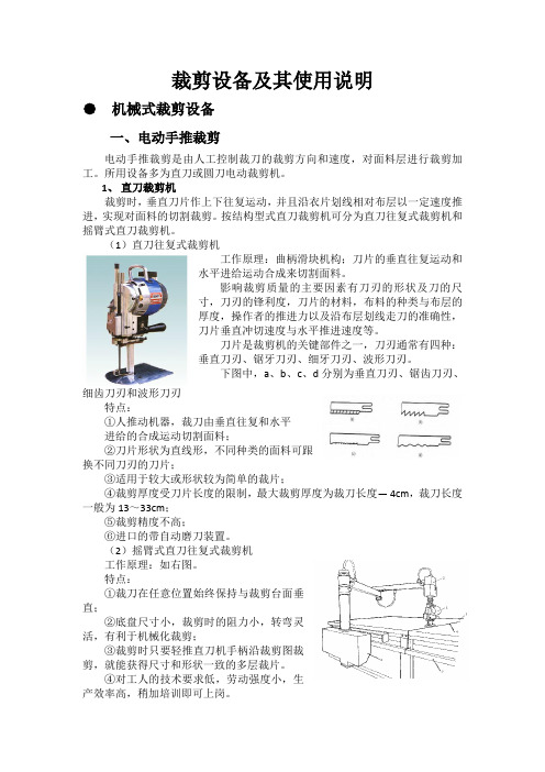
刀片是裁剪机的关键部件之一,刀刃通常有四种:垂直刀刃、锯牙刀刃、细牙刀刃、波形刀刃。
下图中,a、b、c、d分别为垂直刀刃、锯齿刀刃、细齿刀刃和波形刀刃特点:①人推动机器,裁刀由垂直往复和水平进给的合成运动切割面料;②刀片形状为直线形,不同种类的面料可跟换不同刀刃的刀片;③适用于较大或形状较为简单的裁片;④裁剪厚度受刀片长度的限制,最大裁剪厚度为裁刀长度— 4cm,裁刀长度一般为13~33cm;⑤裁剪精度不高;⑥进口的带自动磨刀装置。
(2)摇臂式直刀往复式裁剪机工作原理:如右图。
特点:①裁刀在任意位置始终保持与裁剪台面垂直;②底盘尺寸小,裁剪时的阻力小,转弯灵活,有利于机械化裁剪;③裁剪时只要轻推直刀机手柄沿裁剪图裁剪,就能获得尺寸和形状一致的多层裁片。
④对工人的技术要求低,劳动强度小,生产效率高,稍加培训即可上岗。
小结:直刀裁剪机的使用和选择:①面大而广,服装厂一般都配备②通常有四种:1500r/min、1800r/min、2800r/min、3600r/min③选择带有自动刃磨装置的裁剪机④选用摇臂式自动刃磨直刀式裁剪机时,要注意裁床和裁剪机的配套2、圆刀式裁剪机工作原理:圆刀裁剪机由电机经过一对圆锥齿轮传动使圆刀转动,裁剪时,操作者推电剪在裁剪台上移动切布。
- 1、下载文档前请自行甄别文档内容的完整性,平台不提供额外的编辑、内容补充、找答案等附加服务。
- 2、"仅部分预览"的文档,不可在线预览部分如存在完整性等问题,可反馈申请退款(可完整预览的文档不适用该条件!)。
- 3、如文档侵犯您的权益,请联系客服反馈,我们会尽快为您处理(人工客服工作时间:9:00-18:30)。
SLXC系列变频数控无卡旋切裁板一体机使用说明书【触摸屏用】出厂编号:河北大华宇机械制造有限公司目录一、机床的主要用途----------------------------------------------------------3二、机床的外观图-------------------------------------------------------------3三、机床的规格和技术参数------------------------------------------------4四、机床的构成及主要部件概述------------------------------------------4五、电气系统-------------------------------------------------------------------41、电气原理图--------------------------------------------------------52、电器元件明细表--------------------------------------------------63、常见电器故障---------------------------------------------------74 数控系统操作指南----------------------------------------------8六、机床搬运、安装及调试----------------------------------------------19七、常用调整-----------------------------------------------------------------20八、旋切单板常见问题指导-----------------------------------------------22九、正确使用和维护-------------------------------------------------------23十、合格证明书--------------------------------------------------------------24十一、装箱单--------------------------------------------------------------25十二、产品质量意见书--------------------------------------------------27一、机床的主要用途该机床是人造胶合板生产线上的重要设备,主要用于小径级原木或有卡旋切机剩余木轴的单板旋切。
旋切长度分为1400mm、2200mm、2700mm;旋切直径分为φ300mm以下和φ400mm以下两种;旋切单板厚度从任意选择。
.本机床采用旋切裁板一体的形式,裁板长度可自行设定,从而大大提高了生产率,降低了人工成本。
二、机床的外观图(图一)1——双辊动力2——进刀丝杠3——进刀丝杠母4——进刀伞轮箱5——进刀动力6——输送带7——进刀传动轴8——裁板动力9——单辊动力10——控制系统11——单辊箱12——单排辊13——双排辊筒14——双辊箱15——机架16——旋切刀17——压刀板18——滑道19——刀台20——输送辊121——砧辊22——输送辊223——裁板刀24——单箱转板三、机床的规格和技术参数注:技术参数仅供参考,如有变更,恕不另行通知。
四、机床的构成及主要部件概述1、机床的构成该机床制造精度及各方面配合要求极高,主要由一次加工成型的框架机架,单、双箱;单、双排辊筒及动力系统;胶辊、裁刀、输送带组成的裁板系统;变频电机进给系统;刀台;单箱转板、斜滑道组成的自动调刀缝系统;数控电器柜等组成。
2、各组件概述本机床机架、单双箱部分均为钢板焊接件,双排辊筒与双支架安装于双辊箱上,单辊单箱装于刀台之上,刀台为全焊件,整体加工,通过两端侧滑道运动于机架上。
伺服电机通过减速机伞轮、后传动轴、丝杠、丝母实现进给、快进和快退。
单双辊动力传动系统保证辊筒转速一致。
旋切刀通过压刀板固定在刀台之上,通过调整丝可调整刀刃高度和刀缝大小。
五、电气系统1、电气原理图2、电气元件明细表续表V DF-VE变频器显示屏显示字符说明:4. 旋切裁板一体机数控裁切部分操作指南重要提示:在所有界面当中,用户一般只需调整旋切厚度和裁板宽度;其它参数出厂时已设定好,用户在不了解的情况下,千万注意不要随意更改;主要靠调整机械部分如:刀高、刀缝、单辊压力来达到板厚、板宽的要求。
----------首先调整厚度,以设定厚度与实际厚度相符为准,然后再调整板宽度。
一体机显示界面速查表:(以做厚,裁板宽度650mm为例,仅供参考。
)、开机上电,屏幕上出现界面一,点击【简体中文】进入界面二(界面一)(界面二)如果[界面二]左下角出现[ PLC运行]说明PLC没有运行,机器不能工作。
按[ PLC运行]键开始运行;如果PLC运行正常,[界面二]左下角显示[日期]。
、下面以设定单板厚度,裁切宽度650mm,举例说明:在【界面二】时,点击屏幕上面[厚度设定]进入【界面三】(界面三)、在【界面三】时,可改变[厚度设定]数值,以达到加工各种厚度单板;具体操作按界面详细提示进行。
在此界面中,可实时监测到设定的【厚度设定】以及【圆木直径】和【运行频率】的变化值即设备工作状态。
【刀盒换向阀夹紧】和【刀盒换向阀松开】是液压夹刀功能,为选配。
、如果板子厚度不准确,均匀度不好等问题可以在界面三时点击[补偿参数],然后输密码8个2即,可以进入界面四。
(界面四)【1 厚度校正】此功能是用来改变单板厚度校正值,从而校正设定厚度与实际厚度不符的现象,来使实际厚度与设定厚度吻合。
【2 人工补偿厚度】此功能是指:在木头不圆时,人为增加单板厚度,做一些较为厚的单板。
此功能要配合操作台上的[人工补偿]按钮使用,在木头不圆时按下[人工补偿]按钮,设备按实际厚度加上[人工补偿厚度]值旋切,在木头刚好找完圆时松开[人工补偿]按钮,此时按设定值正常旋切,此值可根据需要设定。
【3 直径补偿】此功能是改变单板前面厚后面薄或前面薄后面厚,操作如下:单板前面厚后面薄补偿改为负数(-1或-2、-3等),前面薄后面厚改为正数(+1、+2、+3等),出厂值是“0”。
【4 旋切补偿长度】是根据刚开始旋切时单板虚尖长度而设定。
【5 旋切补偿厚度】是根据刚开始旋切时的单板厚度而定,一开始板子厚度薄多少就补多少,如果达不到厚度可继续增加。
【6 尾部补偿长度】是指在木轴旋切结束点以前的长度,也就是单板从后向前厚度有偏差的长度。
【7 尾部补偿厚度】是根据单板尾部厚度偏差值而设定,可加可减,从而达到要求的厚度。
【8 尾部补偿结束直径】是指剩余木芯直径,可更改。
【9 旋切补偿选择】是配合【1 厚度校正】和【3 直径补偿】来用的,也就是说改变1、3的值后一定要点击【旋切补偿选择】,否则1、3值程序不执行,选择此按钮后,按钮界面变为绿色。
【10 尾部补偿选择】是配合【6 尾部补偿长度】和【7 尾部补偿厚度】来用的,也就是说改变6、7 的值确定后一定要点击【尾部补偿选择】,否则程序不执行,选择此按钮后,按钮界面变为绿色。
【11 前补开关选择】是配合【4 旋切补偿长度】和【5 旋切补偿厚度】来用的,也就是说改变4、5的值确定后一定要点击【前补开关选择】,否则程序不执行,选择此按钮后,按钮界面变为绿色。
、在【主界面三】时,点击【参数设定】,输入密码8个2,Enter键进入界面五:(界面五)★在界面五中:可改变快进快退的显示数值,从而改变快进快退速度,此值可在20--150Hz之间调整,建议值为50Hz。
【2 上行限位设定】即木头剩余最小直径,可随意改变,此范围为25--100mm,建议值为35mm。
【3 下行限位设定】即木头的最大直径,可随意改变,一般根据木材直径设定,最大值不要超过300或400mm(视机型而定)。
★否则会撞车,造成设备永久损坏(为防止程序故障,本设备装有下行极限硬件开关,出厂已调试好勿动)。
【4 尾部频率限制直径】是指:旋切到此直径时进给频率锁死不再提升,此功能配合【尾部频率限制选择】按钮使用,(此功能基本上不用)。
、在【界面五】时,点击【下一页】,进入界面六:(界面六)【1 气动打轴延迟时间】是指木轴最小时,单双辊停止并开始退车到打木轴气缸开始动作的时间,时间长短可以调整。
此时间应小于【压辊停止时间】。
【2 气动打轴时间】是指打木轴气缸工作时间的长短,时间长短可以调整。
此时间应小于【压辊停止时间】。
【3 压辊停止时间】是指单双辊停止转动到重新启动的间隔时间,时间长短可以调整。
【4 收板延迟时间】和【5 收板时间】暂不选用。
【6 气动打轴使用选择】有打木轴机构的设备才选用,选用时点击【气动打轴使用选择】按钮,按钮变为绿色为选用。
、在【界面五】时,点击【屏幕左上角】,进入界面七:(界面七)输入密码:,点击Ennter键进入界面八:(界面八)【1 界面八】中的参数如:【丝杠螺距】、【压辊直径】、【压辊中心距】、【压辊转速】、【旋切减速比】、【旋切编码器线数】,出厂时已设定好,不要随意更改,否则会造成系统瘫痪。
以上界面中的数值仅供参考,以实际为准(机型不同,参数可能不同)。
【1 原点距离】的数值,不同机数值可能不同,在配电箱右侧,“重点提示”铭牌中查找。
【原点距离】出厂时已设定好,它是整个系统正常工作的关键技术参数,不要随意更改。
【2 圆木直径】数值随张口大小而即时变化。
【3 水平距离】数值随张口大小而即时变化。
【水平距离】示意图;★当【原点距离】接近开关(见整机结构图三)不慎挪动后,或单板均匀度差时,就需要矫正原点距离。
首先将【原点距离】接近开关紧固好,开关端面距检测铁板之间距离不能超过5mm。
如上图所示,测出双排辊筒切面到刀刃的直线距离A,再加上辊筒半径R,(现有辊筒直径为¢99mm、¢110mm、¢103mm,半径R分别为:、55mm、。
不同机型辊筒直径、半径不一样。
)这样A﹢R=【水平距离】测出【水平距离】后,与显示屏显示的【水平距离】数值相比较。
举例:以¢99mm辊筒为例,实测【水平距离】值比显示值大10mm,就在【原点距离】显示值上加10mm,确认后-----【圆木直径】、【水平距离】的数值会自行校正。
若实测值比显示值小10mm,就在【原点距离】显示值上减去10mm,确认后-----【圆木直径】、【水平距离】的数值会自行校正。
、在【界面八】时,点击【下一页】,进入界面九:(界面九)、在【界面二】时,点击【裁板设定】,进入界面十:(界面十)【1 裁切长度】是指设定单板宽度。