信息与计算科学中英文对照外文翻译文献
信息与计算科学相关的英文综述范文

信息与计算科学相关的英文综述范文English:With the rapid advancement of technology, the field of information and computer science has become increasingly indispensable in today's society. Information and computer science is a multidisciplinary field that encompasses a wide range of topics, including data analysis, artificial intelligence, machine learning, cybersecurity, and more. This field plays a crucial role in various industries, such as healthcare, finance, education, and government. Information and computer science also has a significant impact on daily life, as it is involved in the development of various digital technologies, social media platforms, and mobile applications. Research in this field aims to address complex challenges and create innovative solutions to improve efficiency, security, and accessibility of information systems. Overall, the study of information and computer science is essential for understanding and navigating the ever-evolving digital world.中文翻译:随着科技的快速发展,信息与计算科学领域在当今社会变得日益不可或缺。
信息与计算科学中英文对照外文翻译文献

中英文对照外文翻译文献(文档含英文原文和中文翻译)【Abstract】Under the network environment the library information resource altogether constructs sharing is refers to all levels of each kind of library basis user to the social information demand, through network use computer, correspondence, electron, multimedia and so on advanced information technology, the high idealization carries on the synthesis cooperation development and the use activity to various collections information resource and the network resources . The market economy swift and violent development, the networking unceasing renewal, the information age arrival, had decided the future library trend of development will be implements the information resource altogether to construct sharing, already achieved the social mutual recognition about this point.This is because:libraries implement the information resource altogether to construct sharing are solve the knowledge information explosion and the collection strength insufficient this contradictory important way..【Key Words】Network; libraries implement: information: construction;work environment the libraryUnder the network environment the library information resource altogether constructs sharing is refers to all levels of each kind of library basis user to the social information demand, through network use computer, correspondence, electron, multimedia and so on advanced information technology, the high idealization carries on the synthesis cooperation development and the use activity to various collections information resource and the network resources.1、 information resource altogether will construct sharing is the future library development and the use information resource way that must be taken.The market economy swift and violent development, the networking unceasing renewal, the information age arrival, had decided the future library trend of development will be implements the information resource altogether to construct sharing, already achieved the social mutual recognition about this point.This is because: 。
计算机专业外文文献及翻译

计算机专业外文文献及翻译微软Visual Studio1微软Visual Studio是微软公司推出的软软软境~可以用软建来平台下的 Visual Studio Visual StudioWindows软用程序和软软用程序~也可以用软建软服软、智能软软软用程序和网来网插件。
WindowsOffice Visual是一自微软的个来集成软软软境;,~可以用软软由它来微StudioIDEinteqrated development environment软软窗~软手机窗~、框架、精软架框和微软的支持的控制台和软Windows Silverlight 形用软界面的软用程序以及窗体软用程序~站网~软用程序和软服软网中的本地代软软同托管WindowsWeb代软。
包含一由个智能感知和代软重构支持的代软软软器。
集成的软软工作作软一源代软软软既个Visual Studio软器又可以作软一台机器软软软器。
其他置工具包括一软软内个窗体的软用程序~软软软软~软软软软~网数据软架GUI构软软软。
有乎各软面的件增强功能~包括增加软支持它几个插源代软控制系软;如和SubversionVisual,添加新的工具集软软和可软化软软器~如并特定于域的软言或用于其他方面的软件软软生命周期SourceSafe的工具;例如的客软端,软软软源管理器,。
Team Foundation Server支持不同的软程软言的服软方式的软言~允软代软软软器和软软器;在不同程度上,支持它Visual Studio几乎所有的软程软言~提供了一软言特定服软的存在。
置的软言中包括个内中;通软C/C + +Visual C+,;通软,~,中;通软,,和,;作软+,VisualCVisual CFVisual Studio,~软支持其他软言~如和等~可通软安软的软言服软。
软也支持装独它的2010M,Python,Ruby和软特定用软提供服软的也是存在的,微XML/XSLT,HTML/XHTML ,JavaScriptCSS.Visual Studio软~,、,和。
英文文献科技类原文及翻译1
英文文献科技类原文及翻译1On the deployment of V oIP in Ethernet networks:methodology and case studyAbstractDeploying IP telephony or voice over IP (V oIP) is a major and challenging task for data network researchers and designers. This paper outlines guidelines and a step-by-step methodology on how V oIP can be deployed successfully. The methodology can be used to assess the support and readiness of an existing network. Prior to the purchase and deployment of V oIP equipment, the methodology predicts the number of V oIP calls that can be sustained by an existing network while satisfying QoS requirements of all network services and leaving adequate capacity for future growth. As a case study, we apply the methodology steps on a typical network of a small enterprise. We utilize both analysis and simulation to investigate throughput and delay bounds. Our analysis is based on queuing theory, and OPNET is used for simulation. Results obtained from analysis and simulation are in line and give a close match. In addition, the paper discusses many design and engineering issues. These issues include characteristics of V oIP traffic and QoS requirements, V oIP flow and call distribution, defining future growth capacity, and measurement and impact of background traffic. Keywords: Network Design,Network Management,V oIP,Performance Evaluation,Analysis,Simulation,OPNET1 IntroductionThese days a massive deployment of V oIP is taking place over data networks. Most of these networks are Ethernet based and running IP protocol. Many network managers are finding it very attractive and cost effective to merge and unify voice and data networks into one. It is easier to run, manage, and maintain. However, one has to keep in mind that IP networks are best-effort networks that were designed for non-real time applications. On the other hand, V oIP requires timely packet delivery with low latency, jitter, packet loss, andsufficient bandwidth. To achieve this goal, an efficient deployment of V oIP must ensure these real-time traffic requirements can be guaranteed over new or existing IP networks. When deploying a new network service such as V oIP over existing network, many network architects, managers, planners, designers, and engineers are faced with common strategic, and sometimes challenging, questions. What are the QoS requirements for V oIP? How will the new V oIP load impact the QoS for currently running network services and applications? Will my existing network support V oIP and satisfy the standardized QoS requirements? If so, how many V oIP calls can the network support before upgrading prematurely any part of the existing network hardware? These challenging questions have led to the development of some commercial tools for testing the performance of multimedia applications in data networks. A list of the available commercial tools that support V oIP is listed in [1,2]. For the most part, these tools use two common approaches in assessing the deployment of V oIP into the existing network. One approach is based on first performing network measurements and then predicting the network readiness for supporting V oIP. The prediction of the network readiness is based on assessing the health of network elements. The second approach is based on injecting real V oIP traffic into existing network and measuring the resulting delay, jitter, and loss. Other than the cost associated with the commercial tools, none of the commercial tools offer a comprehensive approach for successful V oIP deployment. I n particular, none gives any prediction for the total number of calls that can be supported by the network taking into account important design and engineering factors. These factors include V oIP flow and call distribution, future growth capacity, performance thresholds, impact of V oIP on existing network services and applications, and impact background traffic on V oIP. This paper attempts to address those important factors and layout a comprehensive methodology for a successful deployment of any multimedia application such as V oIP and video conferencing. However, the paper focuses on V oIP as the new service of interest to be deployed. The paper also contains many useful engineering and design guidelines, and discusses many practical issues pertaining to the deployment of V oIP. These issues include characteristics of V oIP traffic and QoS requirements, V oIP flow and call distribution, defining future growth capacity, and measurement and impact of background traffic. As a case study, we illustrate how ourapproach and guidelines can be applied to a typical network of a small enterprise. The rest of the paper is organized as follows. Section 2 presents a typical network topology of a small enterprise to be used as a case study for deploying V oIP. Section 3 outlines practical eight-step methodology to deploy successfully V oIP in data networks. Each step is described in considerable detail. Section 4 describes important design and engineering decisions to be made based on the analytic and simulation studies. Section 5 concludes the study and identifies future work.2 Existing network3 Step-by-step methodologyFig. 2 shows a flowchart of a methodology of eight steps for a successful V oIP deployment. The first four steps are independent and can be performed in parallel. Before embarking on the analysis and simulation study, in Steps 6 and 7, Step 5 must be carried out which requires any early and necessary redimensioning or modifications to the existing network. As shown, both Steps 6 and 7 can be done in parallel. The final step is pilot deployment.3.1. VoIP traffic characteristics, requirements, and assumptionsFor introducing a new network service such as V oIP, one has to characterize first the nature of its traffic, QoS requirements, and any additional components or devices. For simplicity, we assume a point-to-point conversation for all V oIP calls with no call conferencing. For deploying V oIP, a gatekeeper or Call Manager node has to be added to the network [3,4,5]. The gatekeeper node handles signaling for establishing, terminating, and authorizing connections of all V oIP calls. Also a V oIP gateway is required to handle external calls. A V oIP gateway is responsible for converting V oIP calls to/from the Public Switched Telephone Network (PSTN). As an engineering and design issue, the placement of these nodes in the network becomes crucial. We will tackle this issue in design step 5. Otherhardware requirements include a V oIP client terminal, which can be a separate V oIP device, i.e. IP phones, or a typical PC or workstation that is V oIP-enabled. A V oIP-enabled workstation runs V oIP software such as IP Soft Phones .Fig. 3 identifies the end-to-end V oIP components from sender to receiver [9]. The first component is the encoder which periodically samples the original voice signal and assigns a fixed number of bits to each sample, creating a constant bit rate stream. The traditional sample-based encoder G.711 uses Pulse Code Modulation (PCM) to generate 8-bit samples every 0.125 ms, leading to a data rate of 64 kbps . The packetizer follows the encoder and encapsulates a certain number of speech samples into packets and adds the RTP, UDP, IP, and Ethernet headers. The voice packets travel through the data network. An important component at the receiving end, is the playback buffer whose purpose is to absorb variations or jitter in delay and provide a smooth playout. Then packets are delivered to the depacketizer and eventually to the decoder which reconstructs the original voice signal. We will follow the widely adopted recommendations of H.323, G.711, and G.714 standards for V oIP QoS requirements.Table 1 compares some commonly used ITU-T standard codecs and the amount ofone-way delay that they impose. To account for upper limits and to meet desirable quality requirement according to ITU recommendation P.800, we will adopt G.711u codec standards for the required delay and bandwidth. G.711u yields around 4.4 MOS rating. MOS, Mean Opinion Score, is a commonly used V oIP performance metric given in a scale of 1–5, with 5 is the best. However, with little compromise to quality, it is possible to implement different ITU-T codecs that yield much less required bandwidth per call and relatively a bit higher, but acceptable, end-to-end delay. This can be accomplished by applying compression, silence suppression, packet loss concealment, queue management techniques, and encapsulating more than one voice packet into a single Ethernet frame.3.1.1. End-to-end delay for a single voice packetFig. 3 illustrates the sources of delay for a typical voice packet. The end-to-end delay is sometimes referred to by M2E or Mouth-to-Ear delay. G.714 imposes a maximum total one-way packet delay of 150 ms end-to-end for V oIP applications . In [22], a delay of up to 200 ms was considered to be acceptable. We can break this delay down into at least three different contributing components, which are as follows (i) encoding, compression, and packetization delay at the sender (ii) propagation, transmission and queuing delay in the network and (iii) buffering, decompression, depacketization, decoding, and playback delay at the receiver.3.1.2. Bandwidth for a single callThe required bandwidth for a single call, one direction, is 64 kbps. G.711 codec samples 20 ms of voice per packet. Therefore, 50 such packets need to be transmitted per second. Each packet contains 160 voice samples in order to give 8000 samples per second. Each packet is sent in one Ethernet frame. With every packet of size 160 bytes, headers of additional protocol layers are added. These headers include RTP+UDP+IP+Ethernet with preamble of sizes 12+8+20+26, respectively. Therefore, a total of 226 bytes, or 1808 bits, needs to be transmitted 50 times per second, or 90.4 kbps, in one direction. For both directions, the required bandwidth for a single call is 100 pps or 180.8 kbps assuming a symmetric flow.3.1.3. Other assumptionsThroughout our analysis and work, we assume voice calls are symmetric and no voice conferencing is implemented. We also ignore the signaling traffic generated by the gatekeeper. We base our analysis and design on the worst-case scenario for V oIP call traffic. The signaling traffic involving the gatekeeper is mostly generated prior to the establishment of the voice call and when the call is finished. This traffic is relatively small compared to the actual voice call traffic. In general, the gatekeeper generates no or very limited signaling traffic throughout the duration of the V oIP call for an already established on-going call. In this paper, we will implement no QoS mechanisms that can enhance the quality of packet delivery in IP networks.A myriad of QoS standards are available and can be enabled for network elements. QoS standards may i nclude IEEE 802.1p/Q, the IETF’s RSVP, and DiffServ.Analysis of implementation cost, complexity, management, and benefit must be weighed carefully before adopting such QoS standards. These standards can be recommended when the cost for upgrading some network elements is high and the network resources are scarce and heavily loaded.3.2. VoIP traffic flow and call distributionKnowing the current telephone call usage or volume of the enterprise is an important step for a successful V oIP deployment. Before embarking on further analysis or planning phases for a V oIP deployment, collecting statistics about of the present call volume and profiles is essential. Sources of such information are organization’s PBX, telephone records and bills. Key characteristics of existing calls can include the number of calls, number of concurrent calls, time, duration, etc. It is important to determine the locations of the call endpoints, i.e. the sources and destinations, as well as their corresponding path or flow. This will aid in identifying the call distribution and the calls made internally or externally. Call distribution must include percentage of calls within and outside of a floor, building, department, or organization. As a good capacity planning measure, it is recommended to base the V oIP call distribution on the busy hour traffic of phone calls for the busiest day of a week or a month. This will ensure support of the calls at all times with high QoS for all V oIP calls.When such current statistics are combined with the projected extra calls, we can predict the worst-case V oIP traffic load to be introduced to the existing network.Fig. 4 describes the call distribution for the enterprise under study based on the worst busy hour and the projected future growth of V oIP calls. In the figure, the call distribution is described as a probability tree. It is also possible to describe it as a probability matrix. Some important observations can be made about the voice traffic flow for inter-floor and external calls. For all these type of calls, the voice traffic has to be always routed through the router. This is so because Switchs 1 and 2 are layer 2 switches with VLANs configuration. One can observe that the traffic flow for inter-floor calls between Floors 1 and 2 imposes twice the load on Switch 1, as the traffic has to pass through the switch to the router and back to the switch again. Similarly, Switch 2 experiences twice the load for external calls from/to Floor 3.3.3. Define performance thresholds and growth capacityIn this step, we define the network performance thresholds or operational points for a number of important key network elements. These thresholds are to be considered when deploying the new service. The benefit is twofold. First, the requirements of the new service to be deployed are satisfied. Second, adding the new service leaves the network healthy and susceptible to future growth. Two important performance criteria are to be taken into account.First is the maximum tolerable end-to-end delay; and second is the utilization bounds or thresholds of network resources. The maximum tolerable end-to-end delay is determined by the most sensitive application to run on the network. In our case, it is 150 ms end-to-end for V oIP. It is imperative to note that if the network has certain delay sensitive applications, the delay for these applications should be monitored, when introducing V oIP traffic, such that they do not exceed their required maximum values. As for the utilization bounds for network resources, such bounds or thresholds are determined by factors such as current utilization, future plans, and foreseen growth of the network. Proper resource and capacity planning is crucial. Savvy network engineers must deploy new services with scalability in mind, and ascertain that the network will yield acceptable performance under heavy and peak loads, with no packet loss. V oIP requires almost no packet loss. In literature, 0.1–5% packet loss was generally asserted. However, in [24] the required V oIP packet loss was conservatively suggested to be less than 105 . A more practical packet loss, based on experimentation, of below 1% was required in [22]. Hence, it is extremely important not to utilize fully the network resources. As rule-of-thumb guideline for switched fast full-duplex Ethernet, the average utilization limit of links should be 190%, and for switched shared fast Ethernet, the average limit of links should be 85% [25]. The projected growth in users, network services, business, etc. must be all taken into consideration to extrapolate the required growth capacity or the future growth factor. In our study, we will ascertain that 25% of the available network capacity is reserved for future growth and expansion. For simplicity, we will apply this evenly to all network resources of the router, switches, and switched-Ethernet links. However, keep in mind this percentage in practice can be variable for each network resource and may depend on the current utilization and the required growth capacity. In our methodology, the reservation of this utilization of network resources is done upfront, before deploying the new service, and only the left-over capacity is used for investigating the network support of the new service to be deployed.3.4. Perform network measurementsIn order to characterize the existing network traffic load, utilization, and flow, networkmeasurements have to be performed. This is a crucial step as it can potentially affect results to be used in analytical study and simulation. There are a number of tools available commercially and noncommercially to perform network measurements. Popular open-source measurement tools include MRTG, STG, SNMPUtil, and GetIF [26]. A few examples of popular commercially measurement tools include HP OpenView, Cisco Netflow, Lucent VitalSuite, Patrol DashBoard, Omegon NetAlly, Avaya ExamiNet, NetIQ Vivinet Assessor, etc. Network measurements must be performed for network elements such as routers, switches, and links. Numerous types of measurements and statistics can be obtained using measurement tools. As a minimum, traffic rates in bits per second (bps) and packets per second (pps) must be measured for links directly connected to routers and switches. To get adequate assessment, network measurements have to be taken over a long period of time, at least 24-h period. Sometimes it is desirable to take measurements over several days or a week. One has to consider the worst-case scenario for network load or utilization in order to ensure good QoS at all times including peak hours. The peak hour is different from one network to another and it depends totally on the nature of business and the services provided by the network.Table 2 shows a summary of peak-hour utilization for traffic of links in both directions connected to the router and the two switches of the network topology of Fig. 1. These measured results will be used in our analysis and simulation study.外文文献译文以太网网络电话传送调度:方法论与案例分析摘要对网络数据研究者与设计师来说,IP电话或者语音IP电话调度是一项重大而艰巨的任务。
计算机科学与技术 外文翻译 英文文献 中英对照

附件1:外文资料翻译译文大容量存储器由于计算机主存储器的易失性和容量的限制, 大多数的计算机都有附加的称为大容量存储系统的存储设备, 包括有磁盘、CD 和磁带。
相对于主存储器,大的容量储存系统的优点是易失性小,容量大,低成本, 并且在许多情况下, 为了归档的需要可以把储存介质从计算机上移开。
术语联机和脱机通常分别用于描述连接于和没有连接于计算机的设备。
联机意味着,设备或信息已经与计算机连接,计算机不需要人的干预,脱机意味着设备或信息与机器相连前需要人的干预,或许需要将这个设备接通电源,或许包含有该信息的介质需要插到某机械装置里。
大量储存器系统的主要缺点是他们典型地需要机械的运动因此需要较多的时间,因为主存储器的所有工作都由电子器件实现。
1. 磁盘今天,我们使用得最多的一种大量存储器是磁盘,在那里有薄的可以旋转的盘片,盘片上有磁介质以储存数据。
盘片的上面和(或)下面安装有读/写磁头,当盘片旋转时,每个磁头都遍历一圈,它被叫作磁道,围绕着磁盘的上下两个表面。
通过重新定位的读/写磁头,不同的同心圆磁道可以被访问。
通常,一个磁盘存储系统由若干个安装在同一根轴上的盘片组成,盘片之间有足够的距离,使得磁头可以在盘片之间滑动。
在一个磁盘中,所有的磁头是一起移动的。
因此,当磁头移动到新的位置时,新的一组磁道可以存取了。
每一组磁道称为一个柱面。
因为一个磁道能包含的信息可能比我们一次操作所需要得多,所以每个磁道划分成若干个弧区,称为扇区,记录在每个扇区上的信息是连续的二进制位串。
传统的磁盘上每个磁道分为同样数目的扇区,而每个扇区也包含同样数目的二进制位。
(所以,盘片中心的储存的二进制位的密度要比靠近盘片边缘的大)。
因此,一个磁盘存储器系统有许多个别的磁区, 每个扇区都可以作为独立的二进制位串存取,盘片表面上的磁道数目和每个磁道上的扇区数目对于不同的磁盘系统可能都不相同。
磁区大小一般是不超过几个KB; 512 个字节或1024 个字节。
计算机科学外文翻译
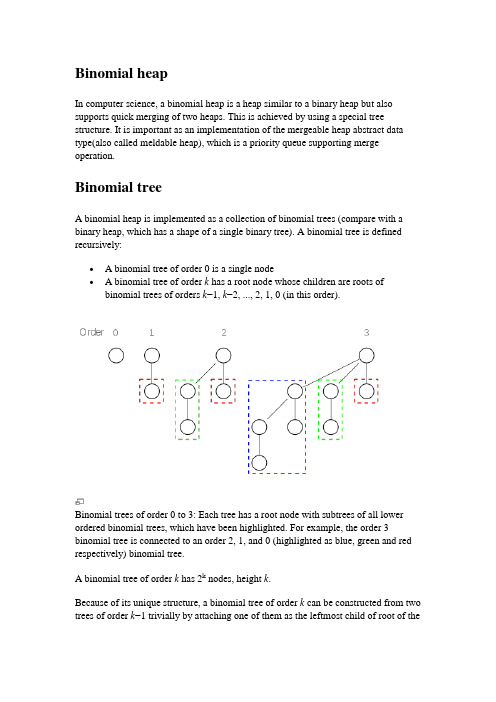
Binomial heapIn computer science, a binomial heap is a heap similar to a binary heap but also supports quick merging of two heaps. This is achieved by using a special tree structure. It is important as an implementation of the mergeable heap abstract data type(also called meldable heap), which is a priority queue supporting merge operation.Binomial treeA binomial heap is implemented as a collection of binomial trees (compare with a binary heap, which has a shape of a single binary tree). A binomial tree is defined recursively:∙ A binomial tree of order 0 is a single node∙ A binomial tree of order k has a root node whose children are roots of binomial trees of orders k−1, k−2, ..., 2, 1, 0 (in this order).Binomial trees of order 0 to 3: Each tree has a root node with subtrees of all lower ordered binomial trees, which have been highlighted. For example, the order 3 binomial tree is connected to an order 2, 1, and 0 (highlighted as blue, green and red respectively) binomial tree.A binomial tree of order k has 2k nodes, height k.Because of its unique structure, a binomial tree of order k can be constructed from two trees of order k−1 trivially by attaching one of them as the leftmost child of root of theother one. This feature is central to the merge operation of a binomial heap, which is its major advantage over other conventional heaps.The name comes from the shape: a binomial tree of order has nodes at depth.Structure of a binomial heapA binomial heap is implemented as a set of binomial trees that satisfy the binomial heap properties:∙Each binomial tree in a heap obeys the minimum-heap property: the key of a node is greater than or equal to the key of its parent.∙There can only be either one or zero binomial trees for each order, including zero order.The first property ensures that the root of each binomial tree contains the smallest key in the tree, which applies to the entire heap.The second property implies that a binomial heap with n nodes consists of at mostlog n + 1 binomial trees. In fact, the number and orders of these trees are uniquely determined by the number of nodes n: each binomial tree corresponds to one digit in the binary representation of number n. For example number 13 is 1101 in binary,, and thus a binomial heap with 13 nodes will consist of three binomial trees of orders 3, 2, and 0 (see figure below).Example of a binomial heap containing 13 nodes with distinct keys.The heap consists of three binomial trees with orders 0, 2, and 3.ImplementationBecause no operation requires random access to the root nodes of the binomial trees, the roots of the binomial trees can be stored in a linked list, ordered by increasing order of the tree.MergeAs mentioned above, the simplest and most important operation is the merging of two binomial trees of the same order within two binomial heaps. Due to the structure of binomial trees, they can be merged trivially. As their root node is the smallest element within the tree, by comparing the two keys, the smaller of them is the minimum key, and becomes the new root node. Then the other tree become a subtree of the combined tree. This operation is basic to the complete merging of two binomial heaps.function mergeTree(p, q)if p.root.key <= q.root.keyreturn p.addSubTree(q)elsereturn q.addSubTree(p)To merge two binomial trees of the same order, first compare the root key. Since 7>3, the black tree on the left(with root node 7) is attached to the grey tree on theright(with root node 3) as a subtree. The result is a tree of order 3.The operation of merging two heaps is perhaps the most interesting and can be used as a subroutine in most other operations. The lists of roots of both heaps are traversed simultaneously, similarly as in the merge algorithmIf only one of the heaps contains a tree of order j, this tree is moved to the merged heap. If both heaps contain a tree of order j, the two trees are merged to one tree of order j+1 so that the minimum-heap property is satisfied. Note that it may later be necessary to merge this tree with some other tree of order j+1 present in one of the heaps. In the course of the algorithm, we need to examine at most three trees of any order (two from the two heaps we merge and one composed of two smaller trees).Because each binomial tree in a binomial heap corresponds to a bit in the binary representation of its size, there is an analogy between the merging of two heaps and the binary addition of the sizes of the two heaps, from right-to-left. Whenever a carry occurs during addition, this corresponds to a merging of two binomial trees during the merge.Each tree has order at most log n and therefore the running time is O(log n).function merge(p, q)while not( p.end() and q.end() )tree = mergeTree(p.currentTree(), q.currentTree())if not heap.currentTree().empty()tree = mergeTree(tree, heap.currentTree())heap.addTree(tree)elseheap.addTree(tree)heap.next() p.next() q.next()This shows the merger of two binomial heaps. This is accomplished by merging two binomial trees of the same order one by one. If the resulting merged tree has the same order as one binomial tree in one of the two heaps, then those two are merged again. InsertInserting a new element to a heap can be done by simply creating a new heap containing only this element and then merging it with the original heap. Due to themerge, insert takes O(log n) time, however it has an amortized time of O(1) (i.e. constant).Find minimumTo find the minimum element of the heap, find the minimum among the roots of the binomial trees. This can again be done easily in O(log n) time, as there are just O(log n) trees and hence roots to examine.By using a pointer to the binomial tree that contains the minimum element, the time for this operation can be reduced to O(1). The pointer must be updated when performing any operation other than Find minimum. This can be done in O(log n) without raising the running time of any operation.Delete minimumTo delete the minimum element from the heap, first find this element, remove it from its binomial tree, and obtain a list of its subtrees. Then transform this list of subtrees into a separate binomial heap by reordering them from smallest to largest order. Then merge this heap with the original heap. Since each tree has at most log n children, creating this new heap is O(log n). Merging heaps is O(log n), so the entire delete minimum operation is O(log n).function deleteMin(heap)min = heap.trees().first()for each current in heap.trees()if current.root < min then min = currentfor each tree in min.subTrees()tmp.addTree(tree)heap.removeTree(min)merge(heap, tmp)Decrease keyAfter decreasing the key of an element, it may become smaller than the key of its parent, violating the minimum-heap property. If this is the case, exchange the element with its parent, and possibly also with its grandparent, and so on, until theminimum-heap property is no longer violated. Each binomial tree has height at most log n, so this takes O(log n) time.DeleteTo delete an element from the heap, decrease its key to negative infinity (that is, some value lower than any element in the heap) and then delete the minimum in the heap.PerformanceAll of the following operations work in O(log n) time on a binomial heap with n elements:∙Insert a new element to the heap∙Find the element with minimum key∙Delete the element with minimum key from the heap∙Decrease key of a given element∙Delete given element from the heap∙Merge two given heaps to one heapFinding the element with minimum key can also be done in O(1) by using an additional pointer to the minimum.二项堆在计算机科学中,二项堆是一个二叉堆类似的堆结构,但是支持两个二项堆快速合并。
计算机科学与技术专业 外文翻译 外文文献 英文文献 记录
外文文献原稿和译文原稿IntroductionThe creation and maintenance of records relating to the students of an institution are essential to:. managing the relationship between the institution and the student;. providing support and other services and facilities to the student;. controlling the student’s academic progress and measuring their achievement, both at the institution and subsequently;. providing support to the student after they leave the institution.In addition, student records contain data which the institution can aggregate and analyse to inform future strategy, planning and service provision.The number of students in HEIs has increased rapidly in the last twenty years. An institution’s relationship with an individual student has also become increasingly complex because of the range of support services institutions now provide to students and life long learning initiatives. Consequently, the volume and complexity of student records have also increased, as have the resources required to create, maintain, use, retain and dispose of them, irrespective of the format in which they are kept. Ensuring that the personal data contained in student records is controlled and managed in line with the principles of the Data Protection Act 1998 creates an additional complication.Institutions should, therefore, establish a policy on managing student records to ensure that they are handled consistently and effectively wherever they are held and whoever holds them. This policy should ensure that:. records relating to an individual student are complete, accurate and up to date;. duplication of student data is deliberate rather than uncontrolled and kept to the minimum needed to support effective administration;. records are held and stored securely to prevent unauthorised access to them;. records relating to the academic aspects of the student’s relationship with the institution are clearly segregated from those dealing with financial, disciplinary, social, support and contractual aspects of that relationship. This will enable differential retention periods to be applied to each of these to meet business and regulatory requirements.What are student records?Records are documents or other items which:. contain recorded information;. are produced or received in the initiation, conduct or completion of an activity;. are retained as evidence of that activity, or because they have other informational value.The recorded information may be in any form (e.g. text, image, sound) and the records may be in any medium or format.Student records –records associated with managing the relationship between an institution and its students –can be organised into three broad categories, each of which may be additionally divided:1. Records documenting the contractual relationship between the student and the institutione.g. records documenting admission and enrolment, payment of tuition fees, non-academic disciplinary proceedings.2. Records documenting the student as a learnere.g. records documenting programmes undertaken, academic progress and performance, awards.3. Records documenting the student as an individual and consumer of services provided by the institutione.g. records documenting use of accommodation services, counseling services, library and IT support services, careers and employment services.Most records in categories 1 and 3 have specific retention periods triggered by the formal end of a student’s direct relationship with an institution, although the information they contain may be aggregated and analyzed to provide data requested by third parties1 orto support the institution’s planning and development activities. An institution will need to retain some of the records in category 2 to provide confirmatory information to potential employers, professional bodies and associations, and to bodies which regulate entry to medical and other professions and which assess and maintain evidence of fitness to practice in those professions.Who is responsible for managing student records?HEI organizational structures vary considerably. As a result, it is difficult to specify exactly where these responsibilities should lie in any one institution.Responsibility for managing student records should be clearly defined and documented. It is important to define the responsibilities of staff involved in: . managing the institution’s general, contractual relationship with the student;. managing the institution’s relationship with the student as a learner;. providing technical and personal support services to the student;for creating, maintaining, using, retaining and disposing of records documenting those activities during the student’s time at the institution.Institutions should also designate one clear point of responsibility for maintaining complete, accurate and up to date records on every student, covering all aspects of the relationship. They should also define the minimum content of the core student record so that the institution can, if required:. demonstrate, within the provisions of limitation statutes, that its implied contract with the student has been fulfilled;. provide information on the student’s academic performance and award(s) to potential employers, to licensing/regulatory bodies (normally first registration only)which control entry to professions and to other organizations (e.g. those providing chartered status) as well as to the student;. provide information on the student as an individual as a means of enabling the institution, or others acting on its behalf, to analyse and aggregate student data for planning and developing its future programmes, recruitment activities and the facilities and services required to support future students.Where and how should student records be stored?The nature of student records and the personal information they contain demands that they should be stored in facilities and equipment (‘hard copy’ records) or electronic systems (digital records) which are, above all, secure and accessible only to authorized staff whose work requires them to have access. In addition, the facilities and equipment should provide: . adequate space for all the records which need to be produced and retained;. appropriate environmental conditions for the record media used.Storage facilities and systems should meet the same standards irrespective of where they are located and who is responsible for managing them.Authorized staff should maintain a record of:. the content, format and location of all student records;. the names and designations of all staff with access to student records, and any limitations on that access;. student records which have been transferred to another part of the institution, particularly after the student has left;. organizations, professional bodies, statutory regulators to whom personal data relating to the student has been provided.Student records should be stored and indexed so that they can be identified and retrieved quickly and easily.. Paper records should be housed in durable containers which carry only an impersonal code number related to a restricted-access list or index to prevent casual, unauthorised access. These containers should be stored in locked equipment or rooms when they are not being used to ensure that the personal data they contain is protected in line with the requirements of the Data Protection Act 1998.. Digital records should be uniquely identified and protected with passwords and other electronic security measures. In all cases, access should be limited to those staff who have ‘a need to know’. If ele ctronic systems are not centrally managed, designated staff should make back-up copies to prevent loss of records through accidental or intentional damage.Whatever its format, the ‘core student record’ shou ld be treated as a vital record and action taken to protect it from disaster or systems failure by copying and dispersal.Student records will become relatively inactive once the student leaves the institution.They may then be transferred to other storage facilities or systems. At this point, duplicates of records created for administrative convenience should be destroyed so that only the designated official records survive.Who should have access to student records?Institutions should tightly control access to student records to prevent unauthorised use, alteration, removal or destruction of the records themselves and unauthorised disclosure of the information they contain. Only those members of staff who need them to do their work should have access to student records and, their access should be restricted to records of the direct relationship and not to the content of the whole file.Student records contain personal data and are therefore subject to the provisions of the Data Protection Act 1998, including the provision that the student, as the data subject, should be given access to personal data held, whether in digital or hard copy form. In addition, the ‘core student record’ as defined by the KCL study includes personal data on the student’s parents which is also subject to the provisions of th e Act.How long should student records be kept?In general, student records should be kept only for as long as is necessary to:. fulfill and discharge the contractual obligations established between the institution and the student, including the completion of any non-academic disciplinary action;. provide information on the academic career and achievements of the student to employers, licensing/regulatory bodies and other organizations, as well as to the student as part of their lifelong learning record;. record the activities of the student as an individual and as a consumer of student support and other institutional services as a means of managing those services and planning and developing them in the future.The nature of the activities which give rise to these categories of records drives their retention.. The contractual relationship between the institution and the student is subject to the same statutory limitations on action as any other contract. This will include records of disciplinary action taken against the student. The records should be disposed of accordingly. The date at which the student leaves the institution normally provides the retention‘trigger’.. The records relating to the student as a learner need to be retained for longer than other student records. Institutions accept that they have an obligation, during a student’s working life, to provide factual information on what they have studied and achieved, i.e. a Transcript. The proposed lifelong learning record or progress file would also include additional data on relevant non-academic achievements and activities (e.g. voluntary work). The retention period for these records should reflect the need to fulfill this obligation over long periods of time, perhaps for the lifetime of the student. It is important to segregate these records from those relating to other aspects of the relationship so that non-academic records are not retained for unnecessarily long periods, consuming storage resources and creating potential breaches of the Data Protection Act 1998.. Records relating to the student as an individual and as a user of student support and institutional services are relatively short term and should be retained for a short finite period once the student leaves the institution. This period should be shorter than for records relating to the wider contractual arrangements.The KCL study proposed the development of a ‘core student record’ which would contain, in addition to the formal transcript, data relating to the background of the student, including parents’ address and occupation, schools attended, first employment, etc. In addition to providing academic information on the individual student, KCL suggested that the availability of this data facilitates its analysis for institutional business planning and development purposes, as well as supporting subsequent academic historical, sociological and demographic research.Individual institutions should decide whether they wish to retain this data for research purposes once immediate institutional business needs have been met. In doing so they will need to take account of:. the cost and technical difficulty of maintaining records, even in summary form, permanently;. the security and subject access implications of retaining personal data relating to named individuals;. the need to create and maintain finding aids so that individual records can be easilyand quickly retrieved when required, particularly to meet subject access requests.How should student records be destroyed?Student records should be destroyed in line with agreed retention periods. Destruction should be authorized by staff with appropriate authority and it should be carried out in accordance with the institution’s procedures for the destruction of redundant rec ords containing personal data.The authority for destruction and the date of destruction should be recorded and held by the section of the institution with final responsibility for the student record.译文介绍创建与维护和学生相关的记录对一个公共机构来说是十分重要的:处理机关和学生之间的关系;提供支持和其他服务以及便利给学生;在机关,控制学生学术进展和测量他们的成就;随后提供支持给学生,在他们离开机关之后。
计算机专业外文文献论文翻译
本科毕业设计外文文献及译文文献、资料题目:Evolving Java Without Changingthe Language文献、资料来源:/articles/evolving-java-no-lang-change 文献、资料发表(出版)日期:院(部):专业:班级:姓名:学号:指导教师:翻译日期:外文文献:Evolving Java Without Changing the Language In "The Feel of Java" James Gosling stated that: Java is a blue collar language. It's not PhD thesis material but a language for a job. Java feels very familiar to many different programmers because I had a very strong tendency to prefer things that had been used a lot over things that just sounded like a good idea.The extraordinary success of Java offers weight to the notion that this was a sensible approach, and if it remains an important goal for Java today, then it makes sense that the language should continue to evolve relatively slowly. In addition to this, the fact that Java is a mature, widely used language causes its evolution to be fraught with difficulty. For one thing, each feature added to the language can change the way it feels in subtle and often unpredictable ways, risking alienating developers who have already adopted it as their language of choice. For another, a feature that makes perfect sense on its own may interact with other features of the language in awkward or unexpected ways. Worse, once a language feature has been added it is all but impossible to remove even if it turns out to be detrimental to the language as a whole. To justify adding a new feature, a language designer must be highly confident that it will be of long term benefit to the language rather than a short term or fashionable solution to a problem that rapidly becomes redundant. To mitigate the risk a language designer will typically experiment by creating a separate language or branch, such as the Pizza language used to experiment with Java's generics, prior to their implementation. The problem with this approach is that the audience for such experiments is both small and self-selecting; obviously they will all be interested in language features, and many may be academics or researchers. An idea which plays well to such an audience may still play badly when it is incorporated into the main language and general programmers start to work with it.To get a sense of this, consider the closures debate that became so heated for Java 7. Implementations for the main proposals (and some others) have been available for some time but no consensus has emerged. In consequence Sun decided that JDK 7 will not get full closures support. The core argument came down to whether Java had become as complex as it could afford to be when generics (and in particular the wildcard syntax) were added to Java 5; andwhether the addition of full support for closures was justified when Java already has a more limited form through anonymous inner classes. Two important use cases for adding full closures support were to simplify working with the fork/join API that is being added to JDK 7 to improve multi-core programming, and to help with resource clean-up. Josh Bloch's ARM block proposal, which is now expected to be in JDK 7 via Project Coin, offers an alternative solution to the latter problem. Dr. Cliff Click's research on a scalable, non-blocking programming style for Java offers an alternative approach to fork/join that may be more appropriate as the number of processor cores increases. If this were to happen, then the uses for closures in Java may arguably be too limited to justify their inclusion.It remains important though that a programming language continues to develop at some level. This article therefore examines three alternative techniques for adding new language features to Java that don't require changes to the language itself - using a custom Domain Specific Language, exploiting the Java 6 annotation processor to add optional language features via a library, and moving the syntactic sugar from the language to the IDE. Each offers the potential to allow a wide audience of mainstream developers to experiment with the new features over the medium term in a non-invasive manner, and the best ideas can then filter down for inclusion in the core language.Custom DSLsThe most widely discussed of the three is the Domain-Specific Language or DSL. There is some disagreement on exactly what the term means, but for the purposes of this discussion we'll refer to it simply as a language that has been created with a narrow focus to solve a particular problem, rather than as a general purpose language designed to solve every computing problem. As such we would expect a DSL to be non-Turing complete and for the most part this is the case. There are edge cases of course. Postscript, for example, is a Turing complete language but also qualifies as a DSL using our definition.As the above example also illustrates, the idea of a DSL is not new. Other familiar DSLs include Regular Expressions, XSLT, Ant, and JSP, all of which require some sort of custom parser to process them. Martin Fowler also suggests that fluent interfaces/APIs can be considered a second type of DSL, which he refers to as an internal DSL. His definition is that an internal DSL is developed directly within the host language. This was a common practice amongst bothLisp and Smalltalk programmers, and more recently the Ruby community has been popularising the technique.Whilst many well-known DSLs are commercially developed and maintained, some enterprise development teams have used the technique to create a language that allows them to rapidly explore aspects of their problem domain. It isn't however as common as it might be, perhaps because DSLs have a fairly intimidating barrier to entry. The team has to design the language, build the parser and possibly other tools to support the programming team, and train each new developer that joins the team on how the DSL works. Here the emergence of tools to specifically support DSL development could significantly change the landscape. Intentional Software's Intentional Domain Workbench, which has been in development longer than Java has been around, is the first significant implementation of such a tool. The project started life at Microsoft Research, and Dr. Charles Simonyi's 1995 paper "The Death of Computer Languages, the Birth of Intentional Programming" describes his vision. In 2002 Simonyi founded Intentional Software to continue working on his ideas and a hugely impressive video demo of the system is available. The product itself is at 1.0 status, but access is restricted to very limited partners.Other software houses are also exploring the concepts, amongst them JetBrains, well respected for their IntelliJ IDEA Java IDE, who have recently released the 1.0 version of their Meta Programming System (MPS). MPS doesn't use a parser, instead working with the Abstract Syntax Tree (AST) directly. It provides a text-like projectional editor which allows the programmer to manipulate the AST, and is used to write languages and programs. For each node in the tree a textual projection is created - as the programmer works with the projection, the change is reflected in the node. This approach allows you to extend and embed languages in any combination (often referred to as language composing) promoting language re-use. JetBrains are using the product internally and have recently released YouTrack, a bug tracking product developed using the system.The Java 6 Annotation ProcessorWhilst DSLs are less common in more mainstream languages such as Java than they are in Ruby, Smalltalk and Lisp, recent developments in the Java language, in particular the annotation processor which was added in Java 6, offer new possibilities for developers looking to use them in Java. The JPA 2.0 criteria API that will ship as part of Java EE 6, itself a DSL, offers anexample. Here the annotation processor builds up a metamodel type for each persistent class in the application. Whilst it would be perfectly possible for the developer to hand craft the metamodel in Java, it would be both tedious and error prone. The use of the annotation processor eliminates that pain and, since the annotation processor is built into Java 6, the approach requires no specific IDE support – an IDE delegates to the annotation processor triggered by the compiler, and the metadata model is generated on the fly.Using the annotation processor it is also possible for a library to add a new language feature. Bruce Chapman's prototype "no closures" proposal, for example, uses the technique to provide a mechanism for casting a method to a Single Abstract Method (SAM) type which compiles on top of Java 6. During our conversation Chapman pointed out that the SAM type also supports free variables, a key aspect of a closure:The method body can declare additional parameters beyond those required for the Single **********************************************.Theseparameterscanhavevaluesbound to them at the point where you obtain an instance of the SAM type, and are then passed to the method each time it is invoked.Chapman also set up the Rapt project to explore other uses of the technique, and has added implementations for two language changes - Multiline Strings and XML literals - that were considered for JDK 7 but won't now make it into the final release. Java could even get a form of closures support using this approach. When asked about this, Chapman said: We are just finishing a Swing project which we used it for. We have found a couple of minor bugs around generic types, one recently discovered remains to be fixed but other than that it seems quite nice to use, and nobody has been wanting to rush back to use conventional anonymous inner classes.Project Lombok, another project exploring the the annotation processor, pushes the technique still further. In effect Lombok uses annotation processing as a hook to run a Java agent that re-writes various javac internals based on the annotations. Since it is manipulating internal classes it is probably not suited to production use (internal classes can change even between minor releases of the JVM) but the project is an eye-opening example of just what can be done using the annotation processor, including:•Support for properties using a pair of @Getter and/or @Setter annotations with varying access levels, e.g. @Setter(AccessLevel.PROTECTED) private String name;•The @EqualsAndHashCode annotation, which generates hashCode() and equals() implementations from the fields of your object•The @ToString annotation, which generates an implementation of the toString() method •The @data method, which is equivalent to combining @ToString, @EqualsAndHashCode, @Getter on all fields, and @Setter on all non-final fields along with a constructor to initialize your final fieldsOther language experimentation, such as removing checked exceptions from Java, can also be done using this approach.Whilst the annotation processor technique opens up a welcome new route to language experimentation, care needs to be taken that the generated code can be easily read by developers, not just by the machine. Chapman made a number of suggestions during our conversation:Generate source code not bytecode, and pay attention to formatting (indenting especially) in the generated code. The compiler won't care whether it is all on one line or not, but your users will. I even sometimes add comments and javadoc in the source code generated by my annotation processors where appropriate.Hopefully if the technique becomes more prevalent IDEs will also make it easier to view the code that is to be generated at compile time.Syntactic Sugar in the IDEBruce Chapman also touches on our third technique - moving the syntactic sugar from the language to the IDE - in his blog and he elaborated on his ideas during our conversation. It is already routine for Java IDEs to create portions of boilerplate code for you such as the getters and setters of a class, but IDE developers are beginning to push the concept further. JetBrains' IntelliJ 9 offers a terse code block syntax for inner classes similar to a closure, which a developer can also type. Acting like code folds, these can then be expanded into the full anonymous inner classes which the compiler works with - this allows developers who prefer to stick with the standard anonymous inner class syntax to do so. A similar plug-in for Eclipse also exists. The key point here is that the "alternate" syntax is just a view of the actual code which the compiler and any source management tools continue to work with. Thus the developer should be able to switchviews between either form (like expanding or collapsing a code fold), and anyone without access to the definition of the sugar just sees the normal Java code. Chapman writes:There are many details to work out in order to make this easily accessible, but long term I see developers relatively easily defining a two way sugaring/desugaring transformation (jackpot is a good start for how this might be done), trying them out, evolving them and sharing the good ones with colleagues and the community. The advantages of this are almost the same as for a language change, without the disadvantages. The very best could become ubiquitous and then form the basis of an actual language change if necessary to get rid of any remaining "noise" not possible with this approach.Since syntactic sugar has to map to another (more verbose) language feature it cannot offer complete closure support; there are some features of BGGA closures for example that cannot be mapped to anonymous inner classes, and so they couldn't be implemented through this approach. Nevertheless the idea opens up the possibility of having various new syntaxes for representing anonymous inner classes, similar to BGGA syntax or FCM syntax, and allowing developers to pick the syntax they want to work with. Other language features, such as the null-safe Elvis operator, could certainly be done this way. To experiment further with the idea this NetBeans module also developed by Chapman, is what he describes as a "barely functional" prototype for Properties using this approach.ConclusionIn language development there is always a trade-off between stability and progress. The advantage that all of these techniques bring is that they don't affect the platform or the language. In consequence they are more tolerant to mistakes and are therefore more conducive to rapid and radical experimentation. With developers freely able to experiment we should begin to see more people separately tackling the poor signal to noise ratio of some common boilerplate such as the anonymous inner class syntax, mixing and evolving these ideas to some optimum form that adds the most value in the most cases. It will be fascinating to see how developers use these different approaches to push the Java platform in new directions.中文译文:不改变语言的前提下推进Java演进James Gosling在“The Feel of Java”中说过:Java是一种蓝领语言,它并不是博士的论文材料而是可以完成工作上的语言。
信息系统信息技术中英文对照外文翻译文献
中英文资料外文翻译文献Information Systems Outsourcing Life Cycle And Risks Analysis 1. IntroductionInformation systems outsourcing has obtained tremendous attentions in the information technology industry.Although there are a number of reasons for companies to pursuing information systems (IS)outsourcing , the most prominent motivation for IS outsourcing that revealed in the literatures was “cost saving”. Costfactor has been a major decision factors for IS outsourcing.Other than cost factor, there are other reasons for outsourcing decision.The Outsourcing Institute surveyed outsourcing end-users from their membership in 1998 and found that top 10 reasons companies outsource were:Reduce and control operating costs,improve company focus,gain access to world-class capabilities,free internal resources for other purposes, resources are not available internally, accelerate reengineering benefits, function difficult to manage/out of control,make capital funds available, share risks, and cash infusion.Within these top ten outsourcing reasons, there are three items that related to financial concerns, they are operating costs, capital funds available, and cash infusion. Since the phenomenon of wage difference exists in the outsourced countries, it is obvious that outsourcing companies would save remarkable amount of labor cost.According to Gartner, Inc.'s report, world business outsourcing services would grow from $110 billion in 2002 to $173 billion in 2007,a proximately 9.5% annual growth rate.In addition to cost saving concern, there are other factors that influence outsourcing decision, including the awareness of success and risk factors, the outsourcing risks identification and management,and the project quality management. Outsourcing activities are substantially complicated and outsourcing project usually carries a huge array of risks. Unmanaged outsourcing risks will increase total project cost, devaluatesoftware quality, delay project completion time, and finally lower the success rate of the outsourcing project.Outsourcing risks have been discovered in areas such as unexpected transition and management costs, switching costs, costly contractual amendments, disputes and litigation, service debasement, cost escalation, loss of organizational competence, hidden service costs,and so on.Most published outsourcing studies focused on organizational and managerial issues. We believe that IS outsourcing projects embrace various risks and uncertainty that may inhibit the chance of outsourcing success. In addition to service and management related risk issues, we feel that technical issues that restrain the degree of outsourcing success may have been overlooked. These technical issues are project management, software quality, and quality assessment methods that can be used to implement IS outsourcing projects.Unmanaged risks generate loss. We intend to identify the technical risks during outsourcing period, so these technical risks can be properly managed and the cost of outsourcing project can be further reduced. The main purpose of this paper is to identify the different phases of IS outsourcing life cycle, and to discuss the implications of success and risk factors, software quality and project management,and their impacts to the success of IT outsourcing.Most outsourcing initiatives involve strategic planning and management participation, therefore, the decision process is obviously broad and lengthy. In order to conduct a comprehensive study onto outsourcing project risk analysis, we propose an IS outsourcing life cycle framework to be served as a yardstick. Each IS outsourcing phase is named and all inherited risks are identified in this life cycle framework.Furthermore,we propose to use software qualitymanagement tools and methods in order to enhance the success rate of IS outsourcing project.ISO 9000 is a series of quality systems standards developed by the International Organization for Standardization (ISO).ISO's quality standards have been adopted by many countries as a major target for quality certification.Other ISO standards such as ISO 9001, ISO 9000-3,ISO 9004-2, and ISO 9004-4 are quality standards that can be applied to the software industry.Currently, ISO is working on ISO 31000, a risk management guidance standard. These ISO quality systems and risk management standards are generic in nature, however, they may not be sufficient for IS outsourcing practice. This paper, therefore,proposes an outsourcing life cycle framework to distinguish related quality and risk management issues during outsourcing practice.The following sections start with needed theoretical foundations to IS outsourcing,including economic theories, outsourcing contracting theories, and risk theories. The IS outsourcing life cycle framework is then introduced.It continues to discuss the risk implications in precontract,contract, and post-contract phases. ISO standards on quality systems and risk management are discussed and compared in the next section. A conclusion and direction for future study are provided in the last section.2. Theoretical foundations2.1. Economic theories related to outsourcingAlthough there are a number of reasons for pursuing IS outsourcing,the cost savingis a main attraction that leads companies to search for outsourcing opportunities. In principle, five outsourcing related economic theories that lay the groundwork of outsourcing practice, theyare:(1)production cost economics,(2)transaction cost theory,(3)resource based theory,(4)competitive advantage, and(5)economies of scale.Production cost economics was proposed by Williamson, who mentioned that “a firm seeks to maximize its profit also subjects to its production function and market opportunities for selling outputs and buying inputs”. It is clear that production cost economics identifies the phenomenon that a firm may pursue the goal of low-cost production process.Transaction cost theory was proposed by Coase. Transaction cost theory implies that in an economy, there are many economic activities occurred outside the price systems. Transaction costs in business activities are the time and expense of negotiation, and writing and enforcing contracts between buyers and suppliers .When transaction cost is low because of lower uncertainty, companies are expected to adopt outsourcing.The focus of resource-based theory is “the heart of the firm centers on deployment and combination of specific inputs rather than on avoidance of opportunities”. Conner suggested that “Firms as seekers of costly-to-copy inputs for production and distribution”.Through resource-based theory, we can infer that “outsourcing decision is to seek external resources or capability for meeting firm's objectives such as cost-saving and capability improving”.Porter, in his competitive forces model, proposed the concept of competitive advantage. Besanko et al.explicated the term of competitive advantage, through economic concept, as “When a firm(or business unit within a multi-business firm) earns a higher rate of economic profit than the average rate of economic profit of other firms competing within the same market, the firm has a competitive advantage.” Outsourcing decision, therefore, is to seek cost saving that meets the goal of competitive advantage within a firm.The economies of scale is a theoretical foundation for creating and sustaining the consulting business. Information systems(IS) and information technology(IT) consulting firms, in essence, bear the advantage of economies of scale since their average costs decrease because they offer a mass amount of specialized IS/IT services in the marketplace.2.2. Economic implication on contractingAn outsourcing contract defines the provision of services and charges that need to be completed in a contracting period between two contracting parties. Since most IS/IT projects are large in scale, a valuable contract should list complete set of tasks and responsibilities that each contracting party needs to perform. The study of contracting becomes essential because a complete contract setting could eliminate possible opportunistic behavior, confusion, and ambiguity between two contracting parties.Although contracting parties intend to reach a complete contract,in real world, most contracts are incomplete. Incomplete contracts cause not only implementing difficultiesbut also resulting in litigation action. Business relationship may easily be ruined by holding incomplete contracts. In order to reach a complete contract, the contracting parties must pay sufficient attention to remove any ambiguity, confusion, and unidentified and immeasurable conditions/ terms from the contract. According to Besanko et al., incomplete contracting stems from the following three factors: bounded rationality, difficulties on specifying or measuring performance, and asymmetric information.Bounded rationality describes human limitation on information processing, complexity handling, and rational decision-making. An incomplete contract stems from unexpected circumstances that may be ignored during contract negotiation. Most contracts consist of complex product requirements and performance measurements. In reality, it is difficult to specify a set of comprehensive metrics for meeting each party's right and responsibility. Therefore, any vague or open-ended statements in contract will definitely result in an incomplete contract. Lastly, it is possible that each party may not have equal access to all contract-relevant information sources. This situation of asymmetric information results in an unfair negotiation,thus it becomes an incomplete contract.2.3. Risk in outsource contractingRisk can be identified as an undesirable event, a probability function,variance of the distribution of outcomes, or expected loss. Risk can be classified into endogenous and exogenous ris ks. Exogenous risks are“risks over which we have no control and which are not affected by our actions.”. For example, natural disasters such as earthquakes and flood are exogenous risks. Endogenous risks are “risks that are dependent on our actions”.We can infer that risks occurring during outsource contracting should belong to such category.Risk (RE) can be calculated through “a function of the probability of a negative outcome and the importance of the loss due to the occurrence of this outcome:RE = ΣiP(UOi)≠L(UOi) (1) where P(UOi) is the probability of an undesirable outcome i, and L(UOi) is the loss due to the undesirable outcome i.”.Software risks can also be analyzed through two characteristics :uncertainty and loss. Pressman suggested that the best way to analyze software risks is to quantify the level of uncertainty and the degree of loss that associated with each kind of risk. His risk content matches to above mentioned Eq.(1).Pressman classified software risks into the following categories: project risks, technical risks, and business risks.Outsourcing risks stem from various sources. Aubert et al. adopted transaction cost theory and agency theory as the foundation for deriving undesirable events and their associated risk factors.Transaction cost theory has been discussed in the Section 2.2. Agency theory focuses on client's problem while choosing an agent(that is, a service provider), and working relationship building and maintenance, under the restriction of information asymmetry.Various risk factors would be produced if such agent–client relationship becomes crumble.It is evident that a complete contract could eliminate the risk that caused by an incomplete contract and/or possible opportunistic behavior prompted by any contracting party. Opportunistic behavior is one of the main sources that cause transactional risk. Opportunistic behavior occurs when a transactional partner observes away of saving cost or removing responsibility during contracting period, this company may take action to pursue such opportunity. This type of opportunistic behavior could be encouraged if such contract was not completely specified at the first place.Outsourcing risks could generate additional unexpected cost to an outsourcing project. In order to conduct a better IS outsourcing project, identifying possible risk factors and implementing matured risk management process could make information systems outsourcing more successful than ever.rmation system outsourcing life cycleThe life cycle concept is originally used to describe a period of one generation of organism in biological system. In essence, the term of life cycle is the description of all activities that a subject is involved in a period from its birth to its end. The life cycle concept has been applied into project management area. A project life cycle, according to Schwalbe, is a collection of project phases such as concept,development, implementation, and close-out. Within the above mentioned four phases, the first two phases center on “planning”activity and the last two phases focus on “delivery the actual work” Of project management.Similarly, the concept of life cycle can be applied into information systems outsourcing analysis. Information systems outsourcing life cycle describes a sequence of activities to be performed during company's IS outsourcing practice. Hirsch heim and Dibbern once described a client-based IS outsourcing life cycle as: “It starts with the IS outsourcing decision, continues with the outsourcing relationship(life of the contract)and ends with the cancellation or end of the relationship, i.e., the end of the contract. The end of the relationship forces a new outsourcing decision.” It is clear that Hirsch heim and Dibbern viewed “outsourcing relationship” as a determinant in IS outsourcing life cycle.IS outsourcing life cycle starts with outsourcing need and then ends with contract completion. This life cycle restarts with the search for a new outsourcing contract if needed. An outsourcing company may be satisfied with the same outsourcing vendor if the transaction costs remain low, then a new cycle goes on. Otherwise, a new search for an outsourcing vendor may be started. One of the main goals for seeking outsourcing contract is cost minimization. Transaction cost theory(discussed in the Section 2.1)indicates that company pursuing contract costs money, thus low transaction cost will be the driver of extending IS outsourcing life cycle.The span of IS outsourcing life cycle embraces a major portion of contracting activities. The whole IS outsourcing life cycle can be divided into three phases(see Fig.1): pre-contract phase, contract phase, and post-contract phase. Pre-contract phase includes activities before a major contract is signed, such as identifying the need for outsourcing, planning and strategic setting, and outsourcing vendor selection. Contract phase startswhile an outsourcing contract is signed and then lasted until the end of contracting period. It includes activities such as contracting process, transitioning process, and outsourcing project execution. Post-contract phase contains those activities to be done after contract expiration, such as outsourcing project assessment, and making decision for the next outsourcing contract.Fig.1. The IS outsourcing life cycleWhen a company intends to outsource its information systems projects to external entities, several activities are involved in information systems outsourcing life cycle. Specifically, they are:1. Identifying the need for outsourcing:A firm may face strict external environment such as stern market competition,competitor's cost saving through outsourcing, or economic downturn that initiates it to consider outsourcing IS projects. In addition to external environment, some internal factors may also lead to outsourcing consideration. These organizational predicaments include the need for technical skills, financial constraint, investors' request, or simply cost saving concern. A firm needs to carefully conduct a study to its internal and external positioning before making an outsourcing decision.2. Planning and strategic setting:If a firm identifies a need for IS outsourcing, it needs to make sure that the decision to outsource should meet with company's strategic plan and objectives. Later, this firm needs to integrate outsourcing plan into corporate strategy. Many tasks need to be fulfilled during planning and strategic setting stages, including determining outsourcing goals, objectives, scope, schedule, cost, business model, and processes. A careful outsourcing planning prepares a firm for pursuing a successful outsourcing project.3. Outsourcing vendor selection:A firm begins the vendor selection process with the creation of request for information (RFI) and request for proposal (RFP) documents. An outsourcing firm should provide sufficient information about the requirements and expectations for an outsourcing project. After receiving those proposals from vendors, this company needs to select a prospective outsourcing vendor, based on the strategic needs and project requirements.4. Contracting process:A contract negotiation process begins after the company selects a probable outsourcing vendor. Contracting process is critical to the success of an outsourcing project since all the aspects of the contract should be specified and covered, including fundamental, managerial, technological, pricing, financial, and legal features. In order to avoid resulting in an incomplete contract, the final contract should be reviewed by two parties' legal consultants.Most importantly, the service level agreements (SLA) must be clearly identified in the contract.5. Transitioning process:Transitioning process starts after a company signed an outsourcing contract with a vendor. Transition management is defined as “the detailed, desk-level knowledge transfer and documentation of all relevant tasks, technologies, workflows, people, and functions”.Transitioni ng process is a complicate phase in IS outsourcing life cycle since it involves many essential workloads before an outsourcing project can be actually implemented. Robinson et al.characterized transition management into the following components:“employee management, communication management, knowledge management, and quality management”. It is apparent that conducting transitioning process needs the capabilities of human resources, communication skill, knowledge transfer, and quality control.6. Outsourcing project execution:After transitioning process, it is time for vendor and client to execute their outsourcing project. There are four components within this“contract governance” stage:project management, relationship management, change management, and risk management. Any items listed in the contract and its service level agreements (SLAs) need to be delivered and implemented as requested. Especially, client and vendor relationships, change requests and records, and risk variables must be carefully managed and administered.7. Outsourcing project assessment:During the end of an outsourcing project period, vendor must deliver its final product/service for client's approval. The outsourcing client must assess the quality of product/service that provided by its client. The outsourcing client must measure his/her satisfaction level to the product/service provided by the client. A satisfied assessment and good relationship will guarantee the continuation of the next outsourcing contract.The results of the previous activity (that is, project assessment) will be the base of determining the next outsourcing contract. A firm evaluates its satisfaction level based on predetermined outsourcing goals and contracting criteria. An outsourcing company also observes outsourcing cost and risks involved in the project. If a firm is satisfied with the current outsourcing vendor, it is likely that a renewable contract could start with the same vendor. Otherwise, a new “precontract phase” would restart to s earch for a new outsourcing vendor.This activity will lead to a new outsourcing life cycle. Fig.1 shows two dotted arrowlines for these two alternatives: the dotted arrow line 3.a.indicates “renewable contract” path and the dotted arrow line 3.b.indicates “a new contract search” path.Each phase in IS outsourcing life cycle is full of needed activities and processes (see Fig.1). In order to clearly examine the dynamics of risks and outsourcing activities, the following sections provide detailed analyses. The pre-contract phase in IS outsourcing life cycle focuses on the awareness of outsourcing success factors and related risk factors. The contract phase in IS outsourcing life cycle centers on the mechanism of project management and risk management. The post-contract phase in IS outsourcing life cycle concentrates on the need of selecting suitable project quality assessment methods.4. Actions in pre-contract phase: awareness of success and risk factorsThe pre-contract period is the first phase in information systems outsourcing life cycle (see Fig.1). While in this phase, an outsourcing firm should first identify its need for IS outsourcing. After determining the need for IS outsourcing, the firm needs to carefully create an outsourcing plan. This firm must align corporate strategy into its outsourcing plan.In order to well prepare for corporate IS outsourcing, a firm must understand current market situation, its competitiveness, and economic environment. The next important task to be done is to identify outsourcing success factors, which can be used to serve as the guidance for strategic outsourcing planning. In addition to know success factors,an outsourcing firm must also recognize possible risks involved in IS outsourcing, thus allows a firm to formulate a better outsourcing strategy.Conclusion and research directionsThis paper presents a three-phased IS outsourcing life cycle and its associated risk factors that affect the success of outsourcing projects.Outsourcing life cycle is complicated and complex in nature. Outsourcing companies usually invest a great effort to select suitable service vendors However,many risks exit in vendor selection process. Although outsourcing costs are the major reason for doing outsourcing, the firms are seeking outsourcing success through quality assurance and risk control. This decision path is understandable since the outcome of project risks represents the amount of additional project cost. Therefore, carefully manage the project and its risk factors would save outsourcing companies a tremendous amount of money.This paper discusses various issues related to outsourcing success, risk factors, quality assessment methods, and project management techniques. The future research may touch alternate risk estimation methodology. For example, risk uncertainty can be used to identify the accuracy of the outsourcing risk estimation. Another possible method to estimate outsourcing risk is through the Total Cost of Ownership(TCO) method. TCO method has been used in IT management for financial portfolio analysis and investment decision making. Since the concept of risk is in essence the cost (of loss) to outsourcing clients, it thus becomes a possible research method to solve outsourcing decision.信息系统的生命周期和风险分析1.绪言信息系统外包在信息技术工业已经获得了巨大的关注。
计算机科学与技术 外文翻译 外文文献 英文文献 提高字符串处理性能的应用程序
1.所译外文资料:Improving String Handling Performance in ASP Applications①作者:James Musson②书名(或论文题目):③出版社(或刊物名称):Developer Services, Microsoft UK④出版时间(或刊号):March 2003外文资料原文摘自:/en-us/library/ms972323.aspxImproving String Handling Performance in ASP ApplicationsJames MussonDeveloper Services, Microsoft UKMarch 2003Summary:Most Active Server Pages (ASP) applications rely on string concatenation to build HTML-formatted data that is then presented to users. This article contains a comparison of several ways to create this HTML data stream, some of which provide better performance than others for a given situation. A reasonable knowledge of ASP and Visual Basic programming is assumed. (11 printed pages)ContentsIntroductionASP DesignString ConcatenationThe Quick and Easy SolutionThe StringBuilderThe Built-in MethodTestingResultsConclusionIntroductionWhen writing ASP pages, the developer is really just creating a stream of formatted text that is written to the Web client via the Response object provided by ASP. You can build this text stream in several different ways and the method you choose can have a large impact on both the performance and the scalability of the Web application. On numerous occasions in which I have helped customers with performance-tuning their Web applications, I have found that one of the major wins has come from changing the way that the HTML stream is created. Inthis article I will show a few of the common techniques and test what effect they have on the performance of a simple ASP page.ASP DesignMany ASP developers have followed good software engineering principles and modularized their code wherever possible. This design normally takes the form of a number of include files that contain functions modeling particular discrete sections of a page. The string outputs from these functions, usually HTML table code, can then be used in various combinations to build a complete page. Some developers have taken this a stage further and moved these HTML functions into Visual Basic COM components, hoping to benefit from the extra performance that compiled code can offer.Although this is certainly a good design practice, the method used to build the strings that form these discrete HTML code components can have a large bearing on how well the Web site performs and scales—regardless of whether the actual operation is performed from within an ASP include file or a Visual Basic COM component.String ConcatenationConsider the following code fragment taken from a function called WriteHTML. The parameter named Data is simply an array of strings containing some data that needs to be formatted into a table structure (data returned from a database, for instance).Copy CodeFunction WriteHTML( Data )Dim nRepFor nRep = 0 to 99sHTML = sHTML & vbcrlf _& "<TR><TD>" & (nRep + 1) & "</TD><TD>" _& Data( 0, nRep ) & "</TD><TD>" _& Data( 1, nRep ) & "</TD><TD>" _& Data( 2, nRep ) & "</TD><TD>" _& Data( 3, nRep ) & "</TD><TD>" _& Data( 4, nRep ) & "</TD><TD>" _& Data( 5, nRep ) & "</TD></TR>"NextWriteHTML = sHTMLEnd FunctionThis is typical of how many ASP and Visual Basic developers build HTML code. The text contained in the sHTML variable is returned to the calling code and then written to the client using Response.Write. Of course, this could also be expressed as similar code embeddeddirectly within the page without the indirection of the WriteHTML function. The problem with this code lies in the fact that the string data type used by ASP and Visual Basic, the BSTR or Basic String, cannot actually change length. This means that every time the length of the string is changed, the original representation of the string in memory is destroyed, and a new one is created containing the new string data: this results in a memory allocation operation and a memory de-allocation operation. Of course, in ASP and Visual Basic this is all taken care of for you, so the true cost is not immediately apparent. Allocating and de-allocating memory requires the underlying runtime code to take out exclusive locks and therefore can be expensive. This is especially apparent when strings get big and large blocks of memory are being allocated and de-allocated in quick succession, as happens during heavy string concatenation. While this may present no major problems in a single user environment, it can cause serious performance and scalability issues when used in a server environment such as in an ASP application running on a Web server.So back to the code fragment above: how many string allocations are being performed here? In fact the answer is 16. In this situation every application of the '&' operator causes the string pointed to by the variable sHTML to be destroyed and recreated. I have already mentioned that string allocation is expensive, becoming increasingly more so as the string grows; armed with this knowledge, we can improve upon the code above.The Quick and Easy SolutionThere are two ways to mitigate the effect of string concatenations, the first is to try and decrease the size of the strings being manipulated and the second is to try and reduce the number of string allocation operations being performed. Look at the revised version of the WriteHTML code shown below.Copy CodeFunction WriteHTML( Data )Dim nRepFor nRep = 0 to 99sHTML = sHTML & ( vbcrlf _& "<TR><TD>" & (nRep + 1) & "</TD><TD>" _& Data( 0, nRep ) & "</TD><TD>" _& Data( 1, nRep ) & "</TD><TD>" _& Data( 2, nRep ) & "</TD><TD>" _& Data( 3, nRep ) & "</TD><TD>" _& Data( 4, nRep ) & "</TD><TD>" _& Data( 5, nRep ) & "</TD></TR>" )NextWriteHTML = sHTMLEnd FunctionAt first glance it may be difficult to spot the difference between this piece of code and the previous sample. This one simply has the addition of parentheses around everything after sHTML = sHTML &. This actually reduces the size of strings being manipulated in most of the string concatenation operations by changing the order of precedence. In the original code sample the ASP complier will look at the expression to the right of the equals sign and just evaluate it from left to right. This results in 16 concatenation operations per iteration involving sHTML which is growing all the time. In the new version we are giving the compiler a hint by changing the order in which it should carry out the operations. Now it will evaluate the expression from left to right but also inside out, i.e. inside the parentheses first. This technique results in 15 concatenation operations per iteration involving smaller strings which are not growing and only one with the large, and growing, sHTML. Figure 1 shows an impression of the memory usage patterns of this optimization against the standard concatenation method.Figure 1 Comparison of memory usage pattern between standard and parenthesized concatenation Using parentheses can make quite a marked difference in performance and scalability in certain circumstances, as I will demonstrate later in this article.The StringBuilderWe have seen the quick and easy solution to the string concatenation problem, and for many situations this may provide the best trade-off between performance and effort to implement. If we want to get serious about improving the performance of building large strings, however, then we need to take the second alternative, which is to cut down the number of stringallocation operations. In order to achieve this a StringBuilder is required. This is a class that maintains a configurable string buffer and manages insertions of new pieces of text into that buffer, causing string reallocation only when the length of the text exceeds the length of the string buffer. The Microsoft .NET framework provides such a class for free (System.Text.StringBuilder) that is recommended for all string concatenation operations in that environment. In the ASP and classic Visual Basic world we do not have access to this class, so we need to build our own. Below is a sample StringBuilder class created using Visual Basic 6.0 (error-handling code has been omitted in the interest of brevity).Copy CodeOption Explicit' default initial size of buffer and growth factorPrivate Const DEF_INITIALSIZE As Long = 1000Private Const DEF_GROWTH As Long = 1000' buffer size and growthPrivate m_nInitialSize As LongPrivate m_nGrowth As Long' buffer and buffer countersPrivate m_sText As StringPrivate m_nSize As LongPrivate m_nPos As LongPrivate Sub Class_Initialize()' set defaults for size and growthm_nInitialSize = DEF_INITIALSIZEm_nGrowth = DEF_GROWTH' initialize bufferInitBufferEnd Sub' set the initial size and growth amountPublic Sub Init(ByVal InitialSize As Long, ByVal Growth As Long)If InitialSize > 0 Then m_nInitialSize = InitialSizeIf Growth > 0 Then m_nGrowth = GrowthEnd Sub' initialize the bufferPrivate Sub InitBuffer()m_nSize = -1m_nPos = 1End Sub' grow the bufferPrivate Sub Grow(Optional MinimimGrowth As Long) ' initialize buffer if necessaryIf m_nSize = -1 Thenm_nSize = m_nInitialSizem_sText = Space$(m_nInitialSize)Else' just growDim nGrowth As LongnGrowth = IIf(m_nGrowth > MinimimGrowth,m_nGrowth, MinimimGrowth)m_nSize = m_nSize + nGrowthm_sText = m_sText & Space$(nGrowth)End IfEnd Sub' trim the buffer to the currently used sizePrivate Sub Shrink()If m_nSize > m_nPos Thenm_nSize = m_nPos - 1m_sText = RTrim$(m_sText)End IfEnd Sub' add a single text stringPrivate Sub AppendInternal(ByVal Text As String) If (m_nPos + Len(Text)) > m_nSize Then Grow Len(Text) Mid$(m_sText, m_nPos, Len(Text)) = Textm_nPos = m_nPos + Len(Text)End Sub' add a number of text stringsPublic Sub Append(ParamArray Text())Dim nArg As LongFor nArg = 0 To UBound(Text)AppendInternal CStr(Text(nArg))Next nArgEnd Sub' return the current string data and trim the bufferPublic Function ToString() As StringIf m_nPos > 0 ThenShrinkToString = m_sTextElseToString = ""End IfEnd Function' clear the buffer and reinitPublic Sub Clear()InitBufferEnd SubThe basic principle used in this class is that a variable (m_sText) is held at the class level that acts as a string buffer and this buffer is set to a certain size by filling it with space characters using the Space$ function. When more text needs to be concatenated with the existing text, the Mid$function is used to insert the text at the correct position, after checking that our buffer is big enough to hold the new text. The ToString function returns the text currently stored in the buffer, also trimming the size of the buffer to the correct length for this text. The ASP code to use the StringBuilder would look like that shown below.Copy CodeFunction WriteHTML( Data )Dim oSBDim nRepSet oSB = Server.CreateObject( "StringBuilderVB.StringBuilder" )' initialize the buffer with size and growth factoroSB.Init 15000, 7500For nRep = 0 to 99oSB.Append "<TR><TD>", (nRep + 1), "</TD><TD>", _Data( 0, nRep ), "</TD><TD>", _Data( 1, nRep ), "</TD><TD>", _Data( 2, nRep ), "</TD><TD>", _Data( 3, nRep ), "</TD><TD>", _Data( 4, nRep ), "</TD><TD>", _Data( 5, nRep ), "</TD></TR>"NextWriteHTML = oSB.ToString()Set oSB = NothingEnd FunctionThere is a definite overhead for using the StringBuilder because an instance of the class must be created each time it is used (and the DLL containing the class must be loaded on the first class instance creation). There is also the overhead involved with making the extra method calls to the StringBuilder instance. How the StringBuilder performs against the parenthesized '&' method depends on a number of factors including the number of concatenations, the size of the string being built, and how well the initialization parameters for the StringBuilder string buffer are chosen. Note that in most cases it is going to be far better to overestimate the amount of space needed in the buffer than to have it grow often. The Built-in MethodASP includes a very fast way of building up your HTML code, and it involves simply using multiple calls to Response.Write. The Write function uses an optimized string buffer under the covers that provides very good performance characteristics. The revised WriteHTML code would look like the code shown below.Copy CodeFunction WriteHTML( Data )Dim nRepFor nRep = 0 to 99Response.Write "<TR><TD>"Response.Write (nRep + 1)Response.Write "</TD><TD>"Response.Write Data( 0, nRep )Response.Write "</TD><TD>"Response.Write Data( 1, nRep )Response.Write "</TD><TD>"Response.Write Data( 2, nRep )Response.Write "</TD><TD>"Response.Write Data( 3, nRep )Response.Write "</TD><TD>"Response.Write Data( 4, nRep )Response.Write "</TD><TD>"Response.Write Data( 5, nRep )Response.Write "</TD></TR>"NextEnd FunctionAlthough this will most likely provide us with the best performance and scalability, we have broken the encapsulation somewhat because we now have code inside our function writing directly to the Response stream and thus the calling code has lost a degree of control. It also becomes more difficult to move this code (into a COM component for example) because the function has a dependency on the Response stream being available.TestingThe four methods presented above were tested against each other using a simple ASP page with a single table fed from a dummy array of strings. The tests were performed using Application Center Test® (ACT) from a single client (Windows® XP Professional, PIII-850MHz, 512MB RAM) against a single server (Windows 2000 Advanced Server, dual PIII-1000MHz, 256MB RAM) over a 100Mb/sec network. ACT was configured to use 5 threads so as to simulate a load of 5 users connecting to the web site. Each test consisted of a 20 second warm up period followed by a 100 second load period in which as many requests as possible were made.The test runs were repeated for various numbers of concatenation operations by varying the number of iterations in the main table loop, as shown in the code fragments for the WriteHTML function. Each test run was performed with all of the various concatenation methods described so far.ResultsBelow is a series of charts showing the effect of each method on the throughput of the application and also the response time for the ASP page. This gives some idea of how manyrequests the application could support and also how long the users would be waiting for pages to be downloaded to their browser.Table 1 Key to concatenation method abbreviations usedWhilst this test is far from realistic in terms of simulating the workload for a typical ASP application, it is evident from Table 2 that even at 420 repetitions the page is not particularly large; and there are many complex ASP pages in existence today that fall in the higher ranges of these figures and may even exceed the limits of this testing range.Table 2 Page sizes and number of concatenations for test samplesNo. of iterations No. of concatenations Page size (bytes)15 240 2,66730 480 4,91745 720 7,16760 960 9,41775 1,200 11,667120 1,920 18,539180 2,880 27,899240 3,840 37,259300 4,800 46,619360 5,760 55,979420 6,720 62,219Figure 2 Chart showing throughput resultsWe can see from the chart shown in Figure 2 that, as expected, the multiple Response.Write method (RESP) gives us the best throughput throughout the entire range of iterations tested. What is surprising, though, is how quickly the standard string concatenation method (CAT) degrades and how much better the parenthesized version (PCAT) performs up to over 300 iterations. At somewhere around 220 iterations the overhead inherent in the StringBuilder method (BLDR) begins to be outweighed by the performance gains due to the string buffering and at anything above this point it would most likely be worth investing the extra effort to use a StringBuilder in this ASP page.Figure 3 Chart showing response time resultsFigure 4 Chart showing response time results with CAT omittedThe charts in Figure 3 and 4 show response time as measured by Time-To-First-Byte in milliseconds. The response times for the standard string concatenation method (CAT) increase so quickly that the chart is repeated without this method included (Figure 4) so that the differences between the other methods can be examined. It is interesting to note that the multiple Response.Write method (RESP) and the StringBuilder method (BLDR) give what looks like a fairly linear progression as the iterations increase whereas the standard concatenation method (CAT) and the parenthesized concatenation method (PCAT) both increase very rapidly once a certain threshold has been passed.ConclusionDuring this discussion I have focused on how different string building techniques can be applied within the ASP environment; but don't forget that this applies to any scenario where you are creating large strings in Visual Basic code, such as manually creating XML documents. The following guidelines should help you decide which method might work best for your situation.∙Try the parenthesized '&' method first, especially when dealing with existing code.This will have very little impact on the structure of the code and you might well find that this increases the performance of the application such that it exceeds your targets.∙If it is possible without compromising the encapsulation level you require, use Response.Write. This will always give you the best performance by avoiding unnecessary in-memory string manipulation.∙Use a StringBuilder for building really large, or concatenation-intensive, strings. Although you may not see exactly the same kind of performance increase shown in this article, I have used these techniques in real-world ASP web applications to deliver very good improvements in both performance and scalability for very little extra effort.2.译成中文:提高字符串处理性能的ASP应用程序摘要:大多数的动态服务器主页(ASP)的应用软件依赖于字串串连建立的HTML格式数据,然后呈现给用户。
- 1、下载文档前请自行甄别文档内容的完整性,平台不提供额外的编辑、内容补充、找答案等附加服务。
- 2、"仅部分预览"的文档,不可在线预览部分如存在完整性等问题,可反馈申请退款(可完整预览的文档不适用该条件!)。
- 3、如文档侵犯您的权益,请联系客服反馈,我们会尽快为您处理(人工客服工作时间:9:00-18:30)。
(文档含英文原文和中文翻译)中英文对照外文翻译基于拉格朗日乘数法的框架结构合理线刚度比的研究【摘要】框架结构是一种常见的多层高层建筑结构;列的合理线刚度比研究是框架结构优化设计中的一个重要方面。
本论文研究合理线刚度比时,框架梁、柱的侧移刚度根据拉格朗日乘数法结构优化的理论和在框架梁、柱的总物质的量一定的前提下,取得最高值。
与传统的估计方法和试算梁柱截面尺寸不同,梁、柱的合理的截面尺寸可以在初步设计阶段由派生的公式计算。
这种方法不仅作为计算框架梁、柱的截面尺寸基础,确认初步设计阶,而且也被用做类似的结构梁柱合理线刚度比研究的参考。
此外,在调整帧梁、柱的截面尺寸的方法的基础上,降低柱的轴向的压缩比,从而达到剪切压缩比和提高结构的延展性。
【关键词】拉格朗日数乘法框架结构刚度比截面尺寸1 引言在混凝土框架结构初步设计的期间,通常,框架梁截面高度通过跨度来估算,和截面宽度根据高宽比估算; 框架柱的截面尺寸是根据柱轴压缩的支持柱的面积的比率估算[1]。
然而,在估计过程中,初步设计阶段中的一个重要的链,未考虑到柱侧移刚度的影响[2]。
列侧移刚度越大,结构层间位的刚度越大,剪切型框架结构的层间位移将越较小。
所以,总结构越小的侧向位移将减少地震灾害[3]所造成的损失。
论文的核心是如何得到列侧移刚度的最大值。
同时,列侧移刚度的值与框架梁-柱线刚度直接相关。
本论文的目的是为了得到一个合理的框架梁 - 柱的线刚度比,在某个控制范围内获得列侧移刚度的最大值。
计算列横向位移的方法有两种方法:刚度拐点点法和修改拐点法。
拐点的方法假定关节的旋转角度为0(当梁柱线性刚度比是大于或等于3时,柱的上端和下端的关节的旋转角度可以取为0,因为它实际上是相当小),即梁的弯曲刚性被视为无穷大。
拐点的方法主要是应用于具有比较少层的框架结构。
但对于多层、高层框架结构,增加柱截面会导致梁柱线刚度比小于3,在水平荷载作用下,框架结构的所有关节的旋转角度的横向位移会发生不可忽视。
因此,一位日本教授武藤提出修改拐点法[4],即D-值方法。
本文采用D-值列侧移刚度的计算法,因为它着重于多层、高层框架结构。
少数在国内外对框架梁柱合理线刚度比的研究,只有梁七黹,源于列侧移刚度的计算方法,比D-值法更加应用广泛;申得氏指出在多层、高层框架结构的柱侧向刚度计算中存在的问题,补充和修改底部和顶部层的列侧向刚度计算公式;应用于史密斯和库尔博士法,焱鑫田源于梁 - 柱线刚度比的合理值,由计算的最大等效刚度框架柱。
本文计算列侧移刚度的最大值,第一次通过采用在约束条件下结构优化理论,那就是,约束Lagrange乘子法优化理论对框架梁-柱的材料是有一定价值[5]。
因此,混凝土框架梁-柱的合理线刚度比在一定范围内可以得到。
在初步设计和参考阶段,得出的结论可以作为梁-柱的截面尺寸的一个决定性因素,类似在梁柱框架结构设计的研究2 用约束拉格朗日乘子法计算框架梁柱的合理线性刚度比2.1 侧向刚度的框架梁-柱的D值法以标准层框架结构的中间关节作为一个例子,由D值法计算出梁-柱的侧向位移刚度::关节旋转的影响系数;:框架柱的线性刚度;:层高;:梁-柱的平均线性刚度;:梁柱的线性刚度;假设所有的梁-柱线性刚度都是,所以,考虑到框架梁铸在原址层的钢筋混凝土框架结构受限的影响,中间框架梁的转动惯量[6];是梁截面的转动惯量,所以,因此,标准的框架柱侧移刚度得出以下公式:因为,侧移刚度列进一步推导出下述公式:2.2 基于拉格朗日乘数法得到合理线刚度比为了获得框架柱的侧移刚度最大D值,我们需要找到目标函数:(1)假设截面框架梁是和截面框架柱是,在材料总量是A的前提下,在材料总量是A的前提下,公式满足这个约束条件,得:(2)通过拉格朗日数乘法来获得目标函数:因为所以(3)E : 混凝土的弹性模量;同理,柱线性刚度可以用下面的公式推导:因此我们得到:(4)把公式(3)和公式(4)代入公式(2),得,可以进一步推导:(5)(T是定值)在一定约束条件下,根据拉格朗日数乘法,目标函数可以由公式(5)得到:(6)分别对求各自的偏导,并且令其偏导数为0,得:整理上述方程,得,(7)从等式(7)对开根号,得:(8)上面的公式是在框架结构标准层中间接头的柱的侧移刚度是最大时的梁-柱线性刚度比,即合理梁柱线刚度比。
同理,我们可以在框架结构柱的侧移刚度是最大时,得出标准层侧接头的合理线刚度比。
(9)3 工程梁柱合理线刚度的应用3.1多层和高层框架结构的合理线刚度应用在消耗材料量是一个定值前提下,框架结构的标准框架层的中间关节作为梁-柱线性刚度比满足式(8),且框架结构标准层框架侧接头作为线性刚度比满足公式(9),那么框架结构侧向位移刚度将一直保持最大值。
显然,那么总的侧向位移是最小的结构就在这时[7]; 其工程应用价值不言而喻。
在一般的框架结构中,柱高和梁跨度满足下面的公式:梁-柱的截面高度比满足下式[8]:对于框架结构的标准层的中间节点,我们可以由等式(8)推出:(10)上文中的计算公式在合理线刚度比的梁-柱框架结构的标准层中间接头的应用范围。
结果表明,梁-柱的截面尺寸可被相应的计算出来,如果梁-柱线性刚度比满足等式(10)时,框架柱的侧向位移则是最大值。
3.2 例子在一般负载下,一个10层的、4跨度的钢筋混凝土浇筑在原址框架结构,每层的高度是3.6米,梁跨度为7.2m,梁-柱的混凝土强度等级是一样的。
在材料量是定值的前提下,中间框的标准层梁 - 柱中间关节的截面尺寸通用估计方法估计,然后将估计值与由式8和式9计算的截面尺寸的结果相比较。
根据一般方法估算梁-柱的截面尺寸:梁:柱:则梁-柱材料的量一共是:那么,柱侧向位移的刚度比是:然而,线性刚度比是在等式10的应用范围之内。
基于等式10,在A是定值的条件下,计算梁柱的截面尺寸,且调整梁柱的截面尺寸,如下:然后,现在侧向位移刚度是:然后,显然,此时,梁柱的线性刚度比在等式10的范围之内,所以它就是合理线性刚度比并且在工程应用范围内。
4 结论(1)在上述的例子可以得出:在梁柱的材料消耗总量A是定值前提下,在标准框架结构的最初设计阶段,如果梁柱的截面尺寸可以调整,梁宽保持不变。
在这个例子中,梁宽保持不变,把柱高从650毫米调整到600毫米,然后把柱高从500毫米调整到560毫米,如果柱截面宽度保持不变,则会得到柱侧向位移刚度的最大值。
证明梁柱的线性刚度比此时满足等式(10),所以在标准框架结构的最初设计阶段,得到的梁柱截面尺寸在应用范围内的合理线性刚度比内。
(2) 该研究方法通过拉格朗日数乘法来获得柱侧向位移刚度最大值被广泛应用于研究类似的框架结构。
例如,可以用于研究中间框架底部、侧向框架、类似工程结构的合理线性刚度比(3) 这个研究的结论可以为框架结构其他方面的研究提供一定的参考。
例如,通过调整截面尺寸获得柱侧向位移刚度的最大值在框架结构的抗震设计中变得越来越重要。
增加柱的截面尺寸可以有效地控制轴压比,剪压缩比,从而提高结构延性和减少地震灾害造成的损失。
参考文献[1]Tao Ji, Zhixiong Huang, Multi-story and High-rise Reinforced ConcreteStructure Design, Michanical Industry Publishing House, Beijing, 2007.[2] Shihua Bao, High-rise Building Structure of New Edition.WaterResource and Hydropower Publishing House of China, Beijing, 2005.[3]Ahmed Ghobarah and A. Said, “Shear strengthening of Beam-columnJoints”, Journal of Engineering Structures,2002, 24(7),pp.881-888.[4] Ahmed Ghobarah, Seism Resistance Design & Seism Resistance Methods[M], Maruzen Company, Limited. 1963.[5] Aichuan. Jiang, Structural Optimization Design, Qinghua PublishingHouse, Beijing, 1986.[6]Xi’an Zhao, High-rise Reinforced Concrete Structure Design,Architecture&Building Press Beijing, China, 2003.[7]P.G. Bakir and H.M. Boduro.lu, “A New Design Equation for Predictingthe Joint Shear Strength of Monotonically Loaded ExteriorBeam-column Joints”, Journal of Engineering Structures, 2002, 24(8), pp.1105-1117.[8]Huanling Meng and Pusheng Shen, “Research on Behaviors of Frame-shearWall Structures Based on Stiffness Degradation”, Journal of Railway Science and Engineering,2006, 3(1), pp.12–17.Study on Reasonable Linear Stiffness Ratio in FrameStructure Based on Lagrange Multiplier Method AbstractFrame structure is a common structure of multistory and high-rise buildings; research on column’s reasonable linear stiffness ratio is an important aspect on frame structure optimization design. The thesis researches on reasonable linear stiffness ratio when the frame beam-column’s lateral displacement stiffness reaches its maximum value based on Lagrange Multiplier Method structure optimization theory and on the premise that total material quantity of framework beam-column is definite. Different from traditional estimation methods and trial calculation on section dimension of beam-column, the reasonable section dimension of beam-column can be calculated by the derived formulas on preliminary design stage. This method is not only used as basis for the frame beam-column’s section dimension confirmation on preliminary design stage, but also taken as reference for research on beam-column’s reasonable linear stiffness ratio for similar structure. In addition, adjusted frame beam-column’s section dimension based on the method reduces the column’s axial compression ratio, shear compression ratio and improve the structural ductility.1 IntroductionDuring the preliminary design of concrete frame structures, generally, the section height of the frame beam is estimated by its span, and section width is estimated according to the height-width ratio; the section dimension of the frame column is estimated by the column axial compression ratio according to the column-supported floor area [1]. Therefore, effects from the column lateral displacement stiffness [2] are not taken into consideration in the process of section estimation, an important chain in the preliminary design stage. The bigger the column lateral displacement stiffness is,the bigger stiffness of structure story displacement will be, but the smaller story displacement in shear-type frame structure will be. As a result, smaller total structure lateral displacement will reduce the loss caused by earthquake disaster [3].The core of the thesis is how to get the maximum value of column lateral displacement stiffness. Meanwhile, column lateral displacement stiffness value is directly related with linear stiffness of frame beam-column.The purpose of the thesis is to get a reasonable linear stiffness ratio of frame beam column within a certain control range after deriving the maximum value of column lateral displacement stiffness.There are two methods of calculating the column lateral displacement stiffness-inflexion point method and modified inflexion point method. Inflexion point method assumes joint rotation angle as 0 ( when linear stiffness ratio of beam-column is more than or equal to 3, joint rotation angle of upper and lower ends of the column can be taken as 0 since it is actually quite small), namely flexural rigidity of beam is regarded as infinity.Inflexion method is mainly applied to the frame structures with fewer stories.But for multi-story and high-rise frame structures, since increasing column section makes beam-column linear stiffness ratio be less than 3, lateral displacement will occur on frame structures and rotation angle of all joints can not be neglected under horizontal load. Accordingly, Muto, a Japanese professor puts forward the modified inflexion point method [4], namely D-value method.The thesis adopts D-value method of calculating the column lateral displacement stiffness because it focuses onmulti-story and high-rise frame structures.Research on reasonable linear stiffness ratio of frame beam-column is few at home and abroad, only Liang Qizhi derives the calculation method of column lateral displacement stiffness which is applied more widely than D-value;Shen Dezhi points out the existing problems in column lateral stiffness calculation for multi-story and high-rise frame structure, supplements and modifies the column lateral stiffness calculation formula on bottom and top layer;applying Smith & Coull method, Yanxin Tian derives the reasonable value of beam-column linear stiffness ratio by calculating the maximal equivalent stiffness of frame column.The thesis calculates the maximal value of column lateral displacement stiffness for the first time by adopting the structure optimization theory under constraint conditions, that is, the constraint Lagrange Multiplier Optimization Theory when the material of frame beam-column is a definite value [5]. Thus, a reasonable lines stiffness ratio of concrete frame beam-column within a certain scope can be obtained.The conclusion can be taken as a decisive factor for section dimension of frame beam-column during preliminary design and the reference on the research of beam-column in similar structure design.2 Reasonable Linear Stiffness Ratio of Frame Beam-column Calculated by Constraint Lagrange Multiplier Method2.1 Lateral Displacement Stiffness of Frame Beam-Column by D Value MethodTaking the middle joint of standard floor frame structure as an example, lateral displacement stiffness of beam-column calculated by D value method:: Influence coefficient of joint rotation;: Linear stiffness of frame column;: Story height;: Average linear stiffness of floor beam-column;: Linear stiffness of beam-column;Suppose all linear stiffness of beam-column is ,Then,Considering the restriction effect on frame beam from cast-in-situ floor of reinforced concrete frame structures, the inertia moment of the middle frame beam [6];is the inertia moment of the beam section, then,Thus, lateral displacement stiffness of standard frame column is derived by the following formula:For , lateral displacement stiffness of columnis further derived from the following formula:2.2 Deriving the Reasonable Linear Stiffness Ratio Based On Lagrange Multiplier MethodIn order to get the maximal lateral displacement stiffness of frame column D value, we need to find the objective function:(1)Suppose the section of frame beam is and section of frame column is , on the premise of total amount of material is definite value A, formula meets the constraint condition, then,(2)To find objective function by Lagrange Multiplier Method:For,Then,(3)E : Elastic modulus of concrete;In the same way, the linear stiffness of column is derived by the following formula:Therefore we get:(4)It can be further derived:(5)(T is a definite value) According to the Lagrange Multiplier Methodunder certain constraints, the objective function can be derived by formula (5):(6)Calculation the partial derivatives of ,respectively and make the results equal to 0, then,Further derive the above formula, then,(7)Derive from Eq.7,(8)The above formula is linear stiffness ratio of beam-column standard floor middle joint in frame structure when the lateral displacement stiffness of column is maximal, namely reasonable linear stiffness ratio of beam-column. In the same way, we can derive the reasonable linear stiffness ratio of standard floor side joint in the frame structure when the lateral displacement stiffness of column is maximal.(9)3 Application of Reasonable Linear Stiffness of Beam-column in Engineering3.1 Application of Reasonable Linear Stiffness in Multi-layer and High-rise Frame StructuresOn the premise that consumed material amount is a definite value, to the middle joints of standard frame floor of frame structures as linear stiffness ratio ofbeam-column satisfies the formula (8) and to side joint of frame standard floor of frame structures as linear stiffness ratio satisfies the formula (9), the lateral displacement stiffness of frame structures will remain the maximum value all the time. Obviously, then the total lateral displacement of the structure is minimal at this moment [7]; its application value in engineering goes without saying. In common frame structures, column height and beam span satisfy the followingformula:h/l=0.3~0.6.The section height ratio of beam-column satisfies the formula [8]:To standard floor middle joint of frame structure, it can be derived from Eq.8,(10)The formula hereinabove is the applied scope of reasonable linear stiffness ratio of beam-column standard floor middle joint in frame structures. The result shows that the section dimension of beam-column can be calculated accordingly if only the linear stiffness ratio of beam-column satisfies Eq.10 and hence the lateral displacement stiffness of the frame column is maximal.3.2 ExampleA 10-story 4-span reinforced concrete cast-in-situ frame structure under general load, the height of each story is 3.6m, beam span is 7.2m, and concrete strength grade of beam-column is the same. On the premise that material amount is a definite value, the section dimension of beam-column middle joint of standard floors in middle frame is estimated by general estimation method and then compare it with calculated section dimension by the results of Eq.8 and Eq.9. Estimate the section dimension ofbeam-column according to general methods:Beam: Column:Then the material amount of beam-column isTherefore, the lateral displacement stiffness of column isHowever, the linear stiffness ratio is beyond the application scope of Eq.10.On the basis of Eq.10, calculate the section dimension of beam-column under the condition that A is a definite value, and adjust the section dimension of beam-column, as:,Then, Now the lateral displacement stiffness isThen, obviously,Now,The linear stiffness of beam-column is within the scope of Eq.10, so it is reasonable linear stiffness ratio and within the engineering application scope.4 Conclusion(1) It can be seen from the example hereinabove: on the premise that the total consumed material quantity A of frame beam-column is a definite value during the preliminary design in the standard frame structure, the beam width remains unchangeable if the section dimension of the beam-column is adjusted slightly. In this example, beam width remains unchangeable, adjust the column height from 650mm to 600mm and then adjust column height from 500mm to 560mm if the column dimension width remains unchangeable, the maximum value of the column lateral displacement stiffness will be obtained. proves that the linear stiffness ratio ofbeam-column at this moment satisfies the formula (10), so the derived beam-column section dimension satisfies the applied scope of the reasonable linear stiffness ratio during the preliminary design in the standard frame structure.(2) The research method obtaining the maximum value of column lateral displacement stiffness by Lagrange Multiplier Method can be widely used to research on the similar frame structures. For example it can be used to research the reasonable linear stiffness ratio of middle frame bottom, side frame, and similar engineering structures.(3) The conclusion of the research will provide certain reference to research on other aspects of frame structure. For example, the method obtaining the maximum value of column lateral displacement stiffness by adjusting its section dimension has great importance in anti-seismic design of frame structures. Increasing section dimension of columns can effectively control the axial compression ratio and shear compression ratio, and hence improve structural ductility and reduce loss due to earthquake disasters.References[1] Tao Ji, Zhixiong Huang, Multi-story and High-rise Reinforced Concrete StructureDesign, Michanical Industry Publishing House, Beijing, 2007.[2] Shihua Bao, High-rise Building Structure of New Edition.Water Resource andHydropower Publishing House of China, Beijing, 2005.[3] Ahmed Ghobarah and A. Said, “She ar strengthening of Beam-column Joints”,Journal of Engineering Structures,2002, 24(7), pp.881-888.[4] Ahmed Ghobarah, Seism Resistance Design & Seism Resistance Methods [M],Maruzen Company, Limited. 1963.[5] Aichuan. Jiang, Structural Optimization Design, Qinghua Publishing House,Beijing, 1986.[6] Xi’an Zhao, High-rise Reinforced Concrete Structure Design, Architecture&Building Press Beijing, China, 2003.[7] P.G. Bakir and H.M. Boduro.lu, “A New Design Equation for Predicting the JointShear Strength of Monotonically Loaded Exterior Beam-column Joints”, Journal of Engineering Structures, 2002, 24(8), pp.1105-1117.[8] Huanling Meng and Pusheng Shen, “Research on Behaviors of Frame-shear WallStructures Based on Stiffness Degradation”, Journal of Railway Science andEngineering,2006, 3(1), pp.12–17.。