Flexural Behavior of FRP-Reinforced Concrete Composite Member
混凝土弯曲韧性评价PCER方法在纤维混凝土中的应用

Influence of fiber type on concrete flexural toughnessJianguo Han 1, a , Peiyu Yan 2,b1 Department of Civil Engineering, Tsinghua University, Beijing, 100084, China2Department of Civil Engineering, Tsinghua University, Beijing, 100084, Chinaahanjg@, b yanpy@Keywords: Concrete, Fiber, Flexural Toughness, Strength, Curing Age.Abstract. Using PCER (post-crack energy ratio) method and plain concrete specimen as reference, the flexural toughness enhancing ability of propylene spinning fiber, propylene monofilament fiber and end-deformed steel fiber was studied. Experiment results show that under the common engineering dosage, the flexural toughness enhancing ability of end-deformed steel fiber is far more outstanding than propylene fibers, and comparing with each other, the flexural toughness enhancing ability of propylene spinning fiber is better than propylene monofilament fiber. As far as one type of fiber is concerned, under the same dosage, along with the enhancement of concrete strength grade, the flexural toughness enhancing ability tends to decrease. Meanwhile, along with enhancement of curing age, the flexural toughness enhancing ability tends to decrease also. IntroductionConcrete is a quasibrittle material, and adding fiber to concrete can enhance its toughness. About fiber type and dosage on the concrete flexural toughness enhancement ability, lots of researches have been done. Balaguru studied fiber type and volume fraction on flexural toughness, and the results show that the volume fraction should increase along with the increase of concrete strength grade to maintain concrete toughness, and fiber of hooked-end geometry works better than corrugated one [1]. Punyamurtula studied the working effect of polymer fiber, and the results show that concrete flexural toughness enhances along with the enhancement of fiber toughness and diameter [2]. Zhou studied the effect of steel fibber volume fraction on concrete toughness, and the results show that along with the increase of fiber volume fraction, the descending tendency of load-deflection curve after peak load becomes soft [3]. But the concrete flexural toughness evaluating method used were somewhat diverse, the methods used including ASTM C1018 specification [4], JSCE SF4 specification [5] and RILEM TC162 specification [6], and the results were lack of comparability since the evaluating method used was different.Based on the aforementioned flexural toughness evaluating methods, the author proposed a new flexural toughness evaluating method named PCER (post-crack energy ratio) method [7]. The PCER method can be used to evaluate the flexural toughness of fiber reinforced concrete and plain concrete as well. In this paper, the flexural toughness enhancing ability of two kinds of propylene fibers and one kind of steel fiber under their common engineering dosage were evaluated using PCER method. Specimen Preparation and Testing ArrangmentMaterials and Mix Proportion. The materials used include P.O 42.5 Portland cement, class F and grade I fly ash, silica fume with amorphous silica content more than 90%, river sand of the fineness modulus 2.8, limestone aggregate of the diameter 5-20mm, and polycarboxylate type water reducer. Concrete of the strength grade C40, C60 and C80 were made with the mix proportion given in Table 1. three kinds of fiber ,under their common engineering dosage were added to concrete to make fiber reinforced concrete, the property and dosage of fibers are given in Table 2.Advanced Materials Research Vols. 287-290 (2011) pp 1179-1183Online available since 2011/Jul/04 at © (2011) Trans Tech Publications, Switzerlanddoi:10.4028//AMR.287-290.1179Concrete specimens with the dimension 150×150×550mm were made. The workability of fresh concrete was adjusted by the dosage of water reducer to be 160mm slump. Fresh concrete was cast to steel mold and consolidated by vibration; concrete specimens were covered with a plastic sheet and cured under room temperature. After demoulding, concrete specimens were cured under standard condition, with T=20˚C and RT≥95%. Concrete flexural toughness was tested at the curing age of 7 and 28 days.Table 1 Concrete mix proportionNumber Cement (kg/m 3) Fly ash (kg/m 3) Silica fume (kg/m 3) Water (kg/m 3) W/B Sand (kg/m 3) Aggregate (kg/m 3) C40 306 102 0 175 0.43 749 1125 C60 375 125 0 150 0.30 720 1060 C8043595401540.276561070Table 2 Property and dosage of fibersNumber Name Diameter (mm) Length (mm) Elastic Moduls(GPa)Tension Strength (MPa) Dosage (kg/m 3) PPSF Propylene spinning fiber 1.0 38.0 ≥5.0 ≥450 7.0 PPMF Propylene monofilamentfiber 0.30 19.0 ≥3.5 ≥400 2.0 EDSFEnd-deformed steel fiber0.5435.0220>100030.0Testing and Evaluating Method. The testing and evaluating of flexural toughness of different fiber reinforced concrete was performed according to PCER method. The dimension of concrete specimen was 150×150×550mm. One day before test, concrete specimens of the due age were take out form the curing room to make a notchof 25mm depth and 3mm width, after that concrete specimen were restored to the curing room until the test. The test apparatus include a loop-control hydraulic machine and a linear variable differential transformer (LVDT) as deflection data collector. The support span of the specimen was 500mm and the deflection speed was 0.2mm/min. The illustration of test arrangement is given in Fig. 1.Fig. 1 Illustration of test arrangementBase on bilinear model, the ascendant branch of PCER method is from the beginning point to peak load, and the descending branch is from peak load to the set deflection point define by the value of K. PCER method evaluates concrete toughness by the area ratio of area under the descending branch of bilinear model to area under the real load-deflection curve after the peak load, as illustrated in Fig. 2 and Eq. 1. Since the area under the load-deflection curve is the energy dissipated during crack propagation, the area ratio is energy ratio in actually. The higher the PCER value calculated by Eq. 1, the higher the flexural toughness of the tested concrete possesses.L o a d (N )δF peakAB CDFig. 2 Illustration of PCER evaluating methodpeak postPCER E 0.5F k=. (1)In which, the PCER value is the energy ratio after the peak load; post E is the area under real load-deflection curve after peak load, defined as the region ABCE in Fig. 1 (N·mm); peak F is the peak load (N); K is the set value, and the recommend scope is 0.1-10mm. During the calculating process using Eq. 1, when the tested ultimate deflection value is lower than the set value of K, post E should be calculated using the real load-deflection curve after peak load until the ultimate deflection value. Results and AnalysisIn this paper, the K value in Eq. 1 is defined as 2.0mm. And based on the load-deflection curve of different fiber reinforced concrete specimens, the influence of fiber type on concrete flexural toughness, the influence of strength grade and curing age on fiber effect are analyzed.Influence of Fiber Type on Flexural Toughness. Fig. 3 manifests the influence of fiber type and concrete strength grade on flexural toughness, in which Fig. 3a shows the analysis results at the curing0.00.40.81.21.6P C ERStrength Grade(3a) 7 days0.00.40.81.2P C E RStrength Grade(3b) 28 daysFig. 3 Influence of fiber type on flexural toughnessNote: The symbol “Control” represents plain concrete, used as reference.From Fig. 3, it can be seen that comparing to the referencing plain concrete, all of the three fibers can enhance concrete flexural toughness, the enhancing ability of steel fiber is far more significant than the other two propylene fibers, and the enhancing tendency of different fiber keep the same regardless of concrete strength grade and curing age. Meanwhile, the flexural toughness enhancing ability of propylene spinning fiber is higher than that of propylene monofilament fiber by comparison.Influence of Strength Grade on Fiber Effect. Fig. 4 manifests the influence of concrete strength grade on fiber effect, in which Fig. 4a shows the analysis results at the curing age 7 days and 4b shows the analysis results at the curing age 28 days. As can be seen that along with the increase of concrete strength grade, the flexural toughness enhancing ability of all fibers decrease no matter of the curing age. Meanwhile, as can be seen also that along with the increase of concrete strength grade, the PCER value of plain concrete decrease, this means that plain concrete flexural toughness decreases alongP C E RFiber Type(4a) 7 days0.00.40.81.2P C E RFiber Type(4b) 28 daysFig. 4 Influence of strength grade on fiber effectInfluence of Curing Age on Fiber Effect. Fig. 5 manifests the influence of curing age on fiber effect, in which Fig. 5a, 5b and 5c shows the analysis results of C40, C60 and C80 concrete separately. As can be seen that along with the increase of curing age, the flexural toughness enhancing ability of all fibers decrease no matter of concrete strength grade. Meanwhile, as can be seen also that along with the increase of curing age, the flexural toughness of plain concrete decreases, this means plain concrete getting brittle along with the increase of curing age.(5a) C40(5b) C60(5c) C80Fig. 5 Influence of curing age on fiber effectConclusionIn this paper, PCER method was adopt to analyze the flexural toughness enhancing ability of three kinds of fiber, under the influence of concrete strength grade and curing age. The following conclusion can be drawn.(1) Comparing to the other two propylene fibers, end-deformed steel fiber has far more higher flexural toughness enhancing ability. Meanwhile, comparing with each other, the flexural toughness enhancing ability of propylene spinning fiber is better than propylene monofilament fiber.(2) For any of the three kinds of fiber, under the same dosage, the flexural toughness enhancing ability decrease along with the increase of concrete strength grade.(3) Along with the increase of curing age, the flexural toughness enhancing ability decrease for all of the three fibers.(4) The flexural toughness of plain concrete decrease along with the increase of strength grade and curing age.AcknowledgmentThis work is supported by the National Science and Technology Supporting Plan of China under grant 2008BAE61B05.References[1] P. Balaguru, R. Narahari, M. Patel: ACI Materials Journal Vol. 89 (1992), p. 541[2] V. K. Punyamurtula, Y. Qiao: International Journal of Damage Mechanics Vol. 17 (2008), p. 363[3] H. T. Zhu, Y. D. Gao, L. Xie and Q. M. Zhang: Journal of The Chinese Ceramic Society Vol. 32(2004), p.656 (In Chinese)[4] ASTM C1018-97 Standard test method for flexural toughness and first-crack strength of fiberreinforced concrete (Using beam with third-point loading) [S][5] JSCE Standard SF4, Method of test for flexural strength and flexural toughness of fiberreinforced concrete[S]. (1984), p.58[6] RILEM TC 162-TDF, Test and design methods of steel fiber reinforced concrete, BENDINGTEST. Materials and Structures Vol. 35 (2002), p.579[7] J. G. Han, P. Y. Yan: China Concrete. (2010), p. 42 (In Chinese)Applications of Engineering Materials10.4028//AMR.287-290Influence of Fiber Type on Concrete Flexural Toughness10.4028//AMR.287-290.1179DOI References[2] V. K. Punyamurtula, Y. Qiao: International Journal of Damage Mechanics Vol. 17 (2008), p.363. /10.1177/1056789508092398。
土木毕业设计外文翻译--近表面埋置加固的钢筋混凝土梁抗弯性能实验研究
中文2630字AN EXPERIMENTAL STUDY ON FLEXURAL BEHAVIOR OF RC BEAMS STRENGTHENED WITH NSM REINFORCEMENTWoo-Tai JUNG1, Young-Hwan PARK2, Jong-SupABSTRACT: This study presents the results of experiments performed on RC (Reinforced Concrete) beams strengthened with NSM(Near Surface Mounted) reinforcement. A total of 6 specimens have been tested. The specimens can be classified into EBR(Externally Bonded Reinforcement) specimen and NSM reinforcements specimens. Two NSM specimens with space variables were strengthened with 2 CFRP(Carbon Fiber Reinforced Polymer) strips. Experimental results revealed that NSMspecimens used CFRP reinforcements moreefficiently than the EBR specimens. Even if CFRP crosssection areas of NSM specimens have 30%,50% of EBR Specimen, the strengthening effect of NSMspecimens is superior to EBR specimen. NSM specimens with space variables showed that thstrengthening effect of the specimen with narrow space is slightly increased as compared to thespecimen with wide spaceu KEYWORDS: carbon fiber reinforced polymer, externally bonded CFRP reinforcements, nearsurface mounted CFRP reinforcements, strengthening1. INTRODUCTIONAmong the various strengthening techniques that have been developed and applied to strengthendeteriorated RC structures, a number of applications using FRP reinforcements have significantly increased recently. FRP reinforcements are bonded to concrete surfaces by adhesives but frequently experience debonding failure at the interface between FRP reinforcements and concrete. Most research, to date, has focused on investigating the strengthening effects and failure modes of EBR systemThe problem of premature failure of EBR system may be solved by increasing the interface between FRP and concrete. Using this principle, the NSM system has been introduced recently. The NSM system for concrete structure using steel reinforcement already began in 1940s. However, the corrosion of the steel reinforcement and the poor bonding performance of the grouting material largely impaired its application. The development of improved epoxy and the adoption of FRP reinforcement offered the opportunity to implement NSM system (Hassan and Rizkalla 2003; Täljsten and Carolin 2001). Because of their light weight, ease of installation, minimal labor costs and site constraints, high strength-to-weight ratios, and durability, FRP repair systems can provide an economically viable alternative to traditional repair systems and materials(Mirmiran et al. 2004). Rizkalla and Hassan (2002) have compared EBR and NSM system in terms of cost, including costs of materials and labor,and strengthening effect. They concluded that the NSM system was more cost-effective than the EBR system using CFRP strips.This experimental study investigates the applicability and strengthening performances of NSM using CFRP strips. For comparison, flexural tests on RC beams strengthened by EBR and by NSM have been performed. In addition, specimens with space variables have been tested to compare the strengthening performance by cross section with wide and narrow space.2. EXPERIMENTAL PROGRAM2.1 MANUFACTURE OF SPECIMENSA total of 6 specimens of simply supported RC beams with span of 3m have been cast. The details andcross-section of the specimens are illustrated in Figure 1. A concrete with compressive strength of31.3 MPa at 28 days has been used. Steel reinforcements D10(φ9.53mm) of SD40 have been arrangedwith steel ratio of 0.0041 and a layer of three D13(φ12.7mm) has been arranged as compressionreinforcements. Shear reinforcements of D10 have been located every 10 cm in the shear zone to avoidshear failure. Table 1 summarizes the material properties used for the test beams.2.2 EXPERIMENTAL PARAMETERSTable 2 lists the experimental parameters. The control specimen, an unstrengthened specimen, has been cast to compare the strengthening performances of the various systems. CPL-50-BOND, EBR specimen, has been strengthened with CFRP strip. The remaining 4 specimens were strengthened with NSM CFRP strips. Among the specimens strengthened with NSM reinforcements, an embedding64 depth of NSM-PL-15 and NSM-PL-25 is 15mm and 25mm, respectively. A space between grooves of NSM-PL-25*2 and NSM-PL-2S is 60mm and 120mm, respectively. The strengthened length of all thespecimens has been fixed to 2,700 mm2.3 INSTALLATION OF THE FRP REINFORCEMENTSFigure 2 shows the details of cross-sections of the specimens. The strengthening process of EBR specimen (CPL-50-BOND) was proceeded by the surface treatment using a grinder, followed by the bonding of the CFRP strip. The strengthened beams were cured at ambient temperature for 7 days for the curing of epoxy adhesive. The process for NSM strengthening progressed by cutting the grooves at the bottom of the beams using a grinder, cleaning the debris, and embedding the CFRP strip after application of the adhesive. The strengthenedbeams were cured for 3 days so that the epoxy adhesive achieves its design strength.2.4 LOADING AND MEASUREMENT METHODSAll specimens were subjected to 4-point bending tests to failure by means of UTM (Universal Testing Machine) with capacity of 980 kN. The loading was applied under displacement control at a speed of 0.02 mm/sec until the first 15 mm and 0.05 mm/sec from15 mm until failure. The measurement of alltest data was recorded by a static data logger anda computer at intervals of 1 second. Electrical resistance strain gauges were fixed at mid-span and L/4 to measure the strain of steel reinforcements.Strain gauges to measure the strain of concrete were located at the top, 5 cm and 10 cm away from the top on one side at mid-span. Strain gauges were also placed on the FRP reinforcement located at the bottom of the mid-span and loaded points to measure the strain according to the loading process.3. EXPERIMENTAL RESULTS3.1 FAILURE MODESBefore cracking, all the strengthened specimens exhibited bending behavior similar to the unstrengthened specimen. This shows that the CFRP reinforcement is unable to contribute to the increase of the stiffness and strength in the elastic domain. However, after cracking, thebending stiffness and strength of the strengthened specimens were seen to increase significantly until failure compared to the unstrengthened specimens.Examining the final failure, the unstrengthened control specimen presented typical bending failure mode which proceeds by the yielding of steel reinforcement followed by compression failure of concrete. The failure of CPL-50-BOND, EBR specimen, began with the separation of CFRP reinforcement and concrete at mid-span to exhibit finally brittle debonding failure (Figure 3). Failure of NSM-PL-15, NSM specimen, occurred with the rupture of the FRP reinforcement. Failure of the remaining NSM specimens(NSM-PL-25, NSM-PL25*2, and NSM-PL-2S) occurred through the simultaneous separation of the CFRP reinforcement and epoxy from concrete (Figure 4, 5, and 6).Table 3 summarizes the failure modes.3.2 STRENGTHENING EFFECTFigure 7 ploted the load-deflection curves of EBR and NSM specimens. The specimens with EBR,CPL-50-BOND, presented ultimate load increased by 30% compared to the unstrengthened specimen, while NSM specimens (NSM-PL-15, NSM-PL-25) increased the ultimate load by 40 to 53%.Observation of Figure 7 reveals that even if CPL-50-BOND with relatively large cross-sectional areaof CFRP reinforcement developed larger initial stiffness, premature debonding failure occurred because its bonding area is much smaller than NSM-PL-15, NSM-PL-25. EBR specimen behaved similarly to the unstrengthened control specimen after debonding failure. In Figure 7, the stiffness of NSM specimens before yielding of steel reinforcement was smaller than the stiffness developed by EBR specimen because NSM specimens have the smaller cross-sectional area of CFRP reinforcement than EBR specimen. The ultimate load and yield load are seen to increasewith the cross-sectional area of NSM reinforcement.Examining the ultimate strain of FRP summarized in Table 3, the maximum strain for EBR specimenappears to attain 30% of the ultimate strain, and 80 to 100% for NSM specimens. This proves that the NSM system is utilizing CFRP reinforcement efficiently(2S with the same cross-sectional area as CPL-50-Bond resented ultimate load increased by 95%, 90% compared to the unstrengthened specimen,respectively. Considering the same cross-sectional area, the strengthening effect of NSM specimens issuperior to the EBR specimen.In Figure 8,NSM-PL-25*2 and NSM-PL-2S, NSM specimens with space variables,showed that the strengthening effect of the specimen with narrow spaceis slightly increased by 2.5%as compared to the specimen with wide space.4. CONCLUSIONSPerformance tests have been carried out on RC beams strengthened with NSM systems. The followingconclusions were derived from the experimental results.It has been seen that NSM specimens utilized the CFRP reinforcement more efficiently than the EBR specimen. According to the static loading test results, the strengthening performances were improvedin NSM specimens compared with EBR specimen. However, the specimens NSM-PL-25, NSM-PL-25*2 and NSM-PL-2S failed by the separation of the CFRP reinforcements and epoxy adhesive from the concrete. Consequently, it is necessary to take somecountermeasures to prevent debonding failure for NSM specimens.Considering the same cross-sectional area, the strengthening effect of NSM specimens is superior to EBR specimen. NSM-PL-25*2 and NSM-PL-2S, NSM specimens with space variables, showed that the strengthening effect ofthe specimen with narrow space is slightly increased as compared to the specimen with wide space.5. REFERENCES1. Hassan, T. and Rizkalla, S. (2003), Investigation of Bond in Concrete Structures Strengthenedwith Near Surface Mounted Carbon Fiber Reinforced Polymer Strips”, Journal of Composites for Construction, Vol 7, No. 3, pp. 248-2572. Täljsten, B. and Carolin, A. (2001), “Concrete Beams Strengthened with Near Surface MountedCFRP Laminates”, Proceeding of the fifth international conference of ibre-reinforced plastics forreinforced concrete structures (FRPRCS-5), Cambridge, UK, 16-18 July 2001, pp. 107-1163. Mirmiran, A., Shahawy, M., Nanni, A., and Karbhari, V. (2004), “Bonded Repair and Retrofit ofConcrete Structures Using FRP Composites”, Recommended Construction Specifications andProcess Control Manual, NCHRP Report 514, Transportation Research Board4. Rizkalla, S., and Hassan, T. (2002), “Effectiveness of FRP for Strengthening Concrete Bridges”,Structural Engineering International, Vol. 12, No. 2, pp. 89-95近表面埋置加固的钢筋混凝土梁抗弯性能实验研究Woo-Tai JUNG1, Young-Hwan PARK2, Jong-Sup PARK3摘要:本研究介绍了近表面贴埋置加固钢筋混凝土(RC)实验结果。
BFRP筋和钢筋混合配筋混凝土梁抗弯承载力计算方法

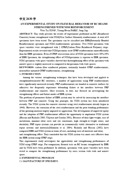
第34卷第1期2022年2月沈阳大学学报(自然科学版)J o u r n a l o f S h e n y a n g U n i v e r s i t y(N a t u r a l S c i e n c e)V o l.34,N o.1F e b.2022文章编号:2095-5456(2022)01-0045-05B F R P 筋和钢筋混合配筋混凝土梁抗弯承载力计算方法周乐,满孝朋(沈阳大学建筑工程学院,辽宁沈阳110044)摘要:为进一步研究混合配筋计算方法,通过对B F R P筋和钢筋进行等强度换算的方式计算出其混合配筋率,基于已有的研究理论基础推导了正截面受弯梁在超筋破坏㊁适筋破坏㊁少筋破坏模式下梁的受弯承载力计算公式,并参考相关文献的试验数据进行了试验值与理论值的对比分析㊂结果表明,理论计算与试验数据吻合较好,本文推导的公式可以为混合配筋混凝土梁提供可靠的参考依据㊂关键词:混合配筋;B F R P筋;等效配筋率;受弯承载力;计算公式中图分类号:T U375.1文献标志码:AC a l c u l a t i o n M e t h o do fF l e x u r a lC a p a c i t y o fC o n c r e t eB e a m s W i t h M i x e dB F R PB a r s a n dS t e e l B a r sZ H O UL e,MA N X i a o p e n g(S c h o o l o f A r c h i t e c t u r a l a n dC i v i l E n g i n e e r i n g,S h e n y a n g U n i v e r s i t y,S h e n y a n g110044,C h i n a)A b s t r a c t:I no r d e r t o f u r t h e r s t u d y t h e c a l c u l a t i o n m e t h o do f t h em i x e dr e i n f o r c e m e n t,t h e r a t i oo ft h e m i x e dr e i n f o r c e m e n t w a sc a l c u l a t e d b y m e a n so fe q u a ls t r e n g t h c o n v e r s i o n b e t w e e nB F R Pb a r sa n ds t e e lb a r s.B a s e do nt h ee x i s t i n g r e s e a r c ht h e o r y,t h ec a l c u l a t i o n f o r m u l a o f t h e f l e x u r a l c a p a c i t y o f t h eb e a m w i t hn o r m a l s e c t i o nu n d e r t h e f a i l u r em o d e so f o v e r-r e i n f o r c e m e n t,s u i t a b l e r e i n f o r c e m e n t a n d l e s s r e i n f o r c e m e n t w a s d e d u c e d.T h e e x p e r i m e n t a la n d t h e o r e t i c a l v a l u e s w e r e c o m p a r e d a n d a n a l y z e d b y r e f e r r i n g t o t h e e x p e r i m e n t a l d a t a i nr e l a t e dl i t e r a t u r e.T h er e s u l t ss h o w e dt h a t t h et h e o r e t i c a l c a l c u l a t i o n w a s i n g o o d a g r e e m e n tw i t h t h e e x p e r i m e n t a l d a t a,a n d t h ed e r i v e d f o r m u l a c o u l d p r o v i d e a r e l i a b l e r e f e r e n c e f o r t h em i x e d r e i n f o r c e d c o n c r e t eb e a m.K e y w o r d s:m i x e dr e i n f o r c e m e n t;B F R P r e i n f o r c e m e n t;e q u i v a l e n tr e i n f o r c e m e n tr a t i o;f l e x u r a l c a p a c i t y;c a l c u l a t i o n f o r m u l a随着工程建设水平的不断提高,人们对建筑物的经济性㊁安全性㊁耐久性提出了更高的要求㊂早期的建筑物以钢筋混凝土结构居多,近年来钢筋混凝土结构存在的问题逐渐暴露出来,比如混凝土的密实性差及钢筋因锈蚀导致耐久性不足等问题㊂吕志涛[1]对钢筋混凝土的耐久性问题作了大量研究,提出可以在混凝土的研制过程中研发新型的外加剂,并寻找抗腐蚀能力强的材料来代替钢筋等改进措施㊂自20世纪70年代以来,F R P(纤维复合材料)材料因具有抗拉强度高㊁耐腐蚀㊁耐久性和抗疲劳性好㊁可设计性强等优势,在工程领域得到广泛应用㊂已有研究表明,材料替换是解决钢筋锈蚀的有效途径[24]㊂研究发现,F R P筋代替钢筋或者与钢筋结合在一起布筋是一种合理的布筋方式[5]㊂F R P筋的制作工艺是将多条成束细纤维采用特制的化学材料进行强有力的胶合之后,经过特制模具的挤压㊁拉拔而成型[68]㊂B F R P(玄武岩纤维复合材料)筋是F R P筋的一种,由于其具有介电性好㊁稳定性高㊁轻质高强㊁绿色环保以及方便取材等优点,被广泛应用于工程中㊂收稿日期:20210417基金项目:国家自然科学基金资助项目(51978416);沈阳科技局中青年科技创新人才支持计划项目(R C190199)㊂作者简介:周乐(1978),女,辽宁营口人,教授,博士生导师㊂1 配筋方式及相关理论传统的钢筋混凝土结构设计是钢筋屈服后利用钢筋所表现出来的大应变来达到构件延性设计的目的㊂而B F R P 筋与传统的普通钢筋不同,B F R P 筋的应力-应变曲线基本成线性状态,没有明显的屈服阶段,其破坏会很突然㊂综合利用钢筋和B F R P 筋的特性,通过混合配筋的形式能够较好地解决混凝土构件因钢筋锈蚀导致抗拉强度降低和耐久性变差的问题㊂为充分发挥B F R P 筋和钢筋的性能优势,合理的布筋方式非常关键㊂本文通过将B F R P 筋放置于受拉区域的外侧,钢筋放置于受拉区域内侧的方式配筋,不仅增大了钢筋的保护层厚度,同时也提高了其抗锈蚀能力,从而结构的耐久性能得到了提升㊂由于B F R P 筋与钢筋在力学性能上的差异,导致混合配筋混凝土梁的抗弯校核公式不同于纯粹F R P 筋混凝土梁和钢筋混凝土梁的抗弯校核公式㊂本文基于已有的研究成果,进一步完善混合配筋梁抗弯承载力公式㊂1.1 基本假定1)截面应符合平截面假定;2)混凝土的抗拉强度忽略不计;3)混凝土与B F R P 筋及钢筋之间应有可靠的黏结强度,避免脱落㊂1.2 本构关系的选取1.2.1 混凝土的本构关系根据‘混凝土结构设计规范“(G B50010 2015)[9]的规定:1)当εc ɤε0时,σc =f c 1-1-εc εæèçöø÷0éëêêùûúún,式中,n =2-160(fc u ,k -50);2)当ε0ɤεc ɤεc u 时,σc =fc ㊂式中:σc 为混凝土压应力;εc 为混凝土的压应变;f c u ,k 为混凝土极限抗压强度;f c 为混凝土轴心抗压强度设计值;ε0为混凝土在f c 时的压应变,εc u 为正截面混凝土的极限压应变;n 为系数,当计算的n 值大于2.0时,取2.0㊂1.2.2 B F R P 筋本构关系为保证经济㊁安全地将F R P 筋应用于实际工程中,参考已有的研究成果[10],B F R P 筋拉伸应力应变关系计算公式为σc =E f εf (0ɤεf ɤεu )㊂式中:σc 为B F R P 筋的应力;εf 为B F R P 筋的应变;E f 为B F R P 筋的抗拉弹性模量;εu 为极限拉应变㊂1.2.3 钢筋的本构关系钢筋的本构关系可分为2个部分:第1部分为钢筋在未达到屈服强度时,其应力-应变曲线呈线弹性关系;第2部分为当钢筋达到屈服强度后变为塑性状态,这种状态一直持续到钢筋的应变达到0.01后钢筋退出工作㊂1.3 等效配筋率由于钢筋和B F R P 筋的材料性质差异,不能直接套用现有规范中的公式计算梁的混合配筋率㊂本文对钢筋和B F R P 筋按照强度相等的原则进行换算[11],即将B F R P 筋的配筋面积转换成等效的钢筋面积,从而可以得到梁的等效配筋率ρs f ,s:ρs f ,s =ρs +ρs e =ρs +f f d ρf f y㊂式中:ρs ㊁ρf 分别为钢筋和B F R P 筋的实际配筋率,ρs e 为B F R P 筋等效成钢筋后的等效配筋率;f y ㊁f f d 分别代表钢筋和B F R P 筋的抗拉强度㊂64沈阳大学学报(自然科学版) 第34卷2 破坏特征及正截面承载力计算方法混合配筋混凝土梁正截面受弯时可能出现超筋破坏㊁适筋破坏㊁少筋破坏,本文根据这3种破坏模式的特征,按照参考文献[11]的计算过程,并对照美国A C I 440.1R -15规范[12]中对混合配筋梁相关系数取值的规定,对混合配筋公式进行修正和完善㊂1)超筋破坏㊂这种破坏模式表现为受压区混凝土被压坏,而受拉区由于配筋率比较高,钢筋和B F R P 筋并未达到极限屈服强度㊂破坏的主要原因是混凝土边缘达到了极限压应变,破坏前无明显征兆,破坏是突然的,因此称为脆性破坏,这种破坏模式在工程领域是不允许的㊂超筋梁的应力㊁应变分布如图1㊁图2所示,图中h 0为梁的有效区高度;εy 为混凝土的极限压应变;M u 1为超筋梁极限承载力;x 0为受压区高度;σs 为钢筋的应力;A s 为钢筋的配筋面积;A f 为B F E P 筋的配筋面积㊂图1 超筋梁应力分布F i g .1 S t r e s s d i s t r i b u t i o no f s u p e r r e i n f o r c e db e a m 图2 超筋梁应变分布F i g .2 S t r a i nd i s t r i b u t i o no f s u pe r r e i nf o r c e db e a m 根据‘混凝土结构设计规范“(G B50010 2015),混凝土受压的应力应变关系为εc u x 0=εs h -x 0-a s =εfh -x 0-a f,(1)σs =εs E s =εc u E s (h -x 0-a s )/x 0,(2)σf =εf E f =εc u E f (h -x 0-a f )/x 0㊂(3) 由梁截面的内力平衡关系,可得:α1fc b x 0=E s εs A s +E f εf A f ㊂(4) 将式(1)~式(4)合并整理后可得x 0,x 0=-E s εc u A s -E f εc uA f 1.7fc b +(E s εc u A s +E f εc u A f )2-40.85f c b (E s A s +E f A f )β1h 0ε[]c u 1.7fc b ,(5)故超筋梁的极限承载力为M u 1=0.85f c b β1x 0(h 0-0.5β1x 0)㊂(6)式中:h ㊁b 分别为混凝土梁的高度和宽度;E s 为钢筋的抗拉弹性模量;εs 为钢盘的应变;a s ㊁a f 分别为钢筋和B F R P 筋到边缘混凝土的距离;系数α1㊁β1按照美国规范A C I 440.1R -15中的规定折减,其中α1取0.85,β1按照β1=0.85-0.05(f c -27.6)/6.9取值㊂2)适筋破坏㊂这种破坏模式下受拉区的钢筋已经屈服,此时B F R P 筋的应力小于或等于其设计拉应力,仍保持线弹性的应力应变关系,截面的破坏主要表现为受压区混凝土被压碎㊂不同于超筋破坏的是在钢筋屈服到混凝土破坏的过程中,钢筋会经历较大的塑性变形,B F R P 筋会承担主要的拉应力,破坏过程有明显的预兆,是实际工程中所期待的模式㊂其计算及应力分布如图3㊁图4所示,图中M u 2为适筋梁的极限承载力;εf d 为BF R P 筋的设计拉应变㊂根据梁截面的内力平衡关系,可得:0.85f c b x 0=f y A s +E f εf A f ㊂(7)将式(2)㊁式(4)㊁式(7)合并整理后可得x 0,x 0=f y A s -E f εc u A f 1.7f c b +(f y A s -E f εc u A f )2+3.4f c b β1h 0E f εc u A f 1.7fc b ,(8)74第1期 周 乐等:B F R P 筋和钢筋混合配筋混凝土梁抗弯承载力计算方法图3 适筋梁受弯承载力计算F i g .3 C a l c u l a t i o no f f l e x u r a l b e a r i n g c a p a c i t yo f r e i n f o r c e db e am图4 适筋梁应力分布F i g.4 S t r e s s d i s t r i b u t i o no f r e i n f o r c e db e a m 图5 少筋梁应力分布F i g.5 S t r e s s d i s t r i b u t i o no f l e s s r e i n f o r c e db e a m 故适筋梁的极限承载力为M u 2=0.85f c b β1x 0(h 0-0.5β1x 0)㊂(9) 3)少筋破坏㊂这种破坏下钢筋已经屈服,钢筋和B F R P 筋的拉应变都已经达到设计拉应变,此时混凝土未完全压碎,主要原因是受拉区配筋率较小㊂破坏时无明显征兆,应力分布如图5所示,实际工程中应尽量避免㊂根据截面的内力平衡,可得:0.85f c b x 0=f yA s +f f d A f ,(10)x 0=h 0εcεc +εf d㊂(11) 将式(11)带入式(10)整理后可得x 0,x 0=(f y A s -f f d εc )1.7fc b +(f y A s +f fd εc )2-3.4f f d εc h 0f cb 1.7fc b ㊂(12) 故少筋梁的极限承载力为M u 3=0.85f c b β1x c (h 0-0.5β1x c )㊂(13)3 结果对比为更好地验证本文推导的抗弯承载力公式的适用性,本文参考了文献[13]所作的关于钢/B F R P 筋混合配筋梁受弯性能试验研究,试验共做了5根混凝土梁:包括1根普通钢筋混凝土梁L 1;1根B F R P 增强混凝土梁L 5;3根F R P 与钢筋混杂配筋梁L 2㊁L 3㊁L 4(其中L 4的纵向受力筋采用双层等间距布置)㊂根据式(9)得出的适筋破坏模式下的受弯承载力M u b 和文献[13]的试验结果M u a 见表1㊂表1 B F R P 筋与钢筋混合配筋混凝土适筋梁承载力结果对比T a b l e1 C o m p a r i s o no f t h eb e a r i n g c a p a c i t y o f r e i n f o r c e dc o n c r e t eb e a m sw i t hm i x e dB F R Pb a r s a n d s t e e l b a r s 梁号A s /mm2A f /mm2M u a/(k N ㊃m )M u b/(k N ㊃m )M u a /M u b L 1226.253.4L 2157.0193.6101.398.21.03L 3157.0211.4118.2107.51.09L 4157.0211.4124.2125.30.99L 5942.9174.3本文还参考了文献[14]中对于钢筋和B F R P 筋混合配筋超筋梁和少筋梁的试验研究部分,试件包括1根超筋梁(L 6),3根配筋面积比不同的少筋混合配筋混凝土梁L 7㊁L 8㊁L 9,4根梁的尺寸相同,宽度为180mm ㊁高为250mm ㊁长为2100mm ㊂将式(6)㊁式(13)的计算结果M u d 分别与文献[14]中梁L 6~L 9中的试验值M u c 对比,其结果见表2㊂从表1㊁表2中可以看到,本文推导的公式计算出的混合配筋混凝土梁的抗弯承载力的误差在可接受的范围内㊂84沈阳大学学报(自然科学版) 第34卷表2 B F R P 筋与钢筋混合配筋混凝土少筋梁和超筋梁的受弯承载力结果对比T a b l e2 C o m p a r i s o no f f l e x u r a l b e a r i n g c a p a c i t y of r e i n f o r c e dc o n c r e t eb e a m sw i t h f e w a n do v e r r e i n f o r c e dc o n c r e t eb e a m sw i t hm i x e dB F R Pb a r s a n d s t e e l b a r s梁编号破坏模式配筋面积比A f /A s 文献[14]试验结果M u c /(k N ㊃m )本文计算结果M u d /(k N ㊃m )M u c /M u dL 6超筋破坏310.0315.20.98L 7少筋破坏0.36121.9124.80.97L 8少筋破坏1.00139.8137.71.01L 9少筋破坏2.78159.5156.21.024 结 论1)结合钢筋混凝土受弯承载力相关理论基础,采用等效抗拉强度换算法定义混合配筋梁的等效配筋率㊂2)本文基于已有理论公式,结合美国规范的折减系数.推导出B F R P 筋和钢筋混合配筋时混凝土梁在超筋㊁适筋和少筋破坏模式下其正截面受弯承载力的建议计算公式㊂3)本文推导的公式能够较好地与试验数据吻合,且误差控制在可接受的范围内,可以为混合配筋梁计算承载力的研究和应用提供参考㊂参考文献:[1]吕志涛.高性能材料F R P 应用与结构工程创新[J ].建筑科学与工程学报,2005,22(1):15.L Y UZT.A p p l i c a t i o no fh i g h p e r f o r m a n c eF R Pa n d i n n o v a t i o n so f s t r u c t u r ee n g i n e e r i n g [J ].J o u r n a l o fB u i l d i n g Sc i e n c ea nd E n g i ne e r i n g ,2005,22(1):15.[2]岳清瑞.我国碳纤维(C F R P )加固修复技术研究应用现状与展望[J ].工业建筑,2000,30(10):2326.Y U E Q R.P r e s e n ts t a t u so fr e s e a r c ha n da p p l i c a t i o no fs t r e n g t h e n i n g a n dr e p a i r i n g t e c h n o l o g y wi t hc a r b o nf i b r er e i n f o r c e d pl a s t i c s (C F R P )a n d i t s o u t l o o k i nC h i n a [J ].I n d u s t r i a l C o n s t r u c t i o n ,2000,30(10):2326.[3]滕锦光,陈建飞,史密斯,等.F R P 加固混凝土结构[M ].李荣,滕锦光,顾磊,译.北京:中国建筑工业出版社,2005.T E N GJG ,C H E NJF ,S M I T H ,e ta l .F R Ps t r e n g t h e n e dR Cs t r u c t u r e s [M ].L IR ,T E N GJG ,G U L ,t r a n s .B e i j i n g:C h i n a A r c h i t e c t u r e&B u i l d i n g Pr e s s ,2005.[4]叶列平,冯鹏.F R P 在工程结构中的应用与发展[J ].土木工程学报,2006,39(3):2436.Y ELP ,F E N GP .A p p l i c a t i o n s a n d d e v e l o p m e n t o f f i b e r -r e i n f o r c e d p o l y m e r i n e n g i n e e r i n g s t r u c t u r e s [J ].C h i n aC i v i l E n g i n e e r i n g J o u r n a l ,2006,39(3):2436.[5]P A N GL ,Q U WJ ,Z HUP ,e t a l .D e s i g n p r o p o s i t i o n s f o r h y b r i dF R P -s t e e l r e i n f o r c e d c o n c r e t eb e a m s [J ].J o u r n a l o fC o m po s i t e s f o rC o n s t r u c t i o n ,2016,20(4):04015086.[6]朱海堂,程晟钊,高丹盈,等.B F R P 筋钢纤维高强混凝土梁受弯承载力试验与理论[J ].复合材料学报,2018,35(12):33133323.Z HU H T ,C H E N GSZ ,G A O D Y ,e t a l .E x p e r i m e n t a l a n dt h e o r e t i c a l s t u d y o nt h e f l e x u r a l c a p a c i t y o fh i g h -s t r e n g t hc o n c r e t e b e a m s r e i n f o r c e dw i t hB F R Pb a r s a n d s t e e l f i b e r [J ].A c t aM a t e r i a eC o m po s i t a eS i n i c a ,2018,35(12):33133323.[7]周乐.G F R P 管钢骨高强混凝土组合构件力学性能研究[D ].沈阳:东北大学,2009.Z HO U L .M e c h a n i c a l b e h a v i o r s s t u d y o fG F R Pt u b e f i l l e dw i t hs t e e l -r e i n f o r c e dh i g h -s t r e n g t hc o n c r e t e c o m p o s i t em e m b e r s [D ].S h e n y a n g :N o r t h e a s t e r nU n i v e r s i t y,2009.[8]孔祥清,于洋,邢丽丽,等.B F R P 筋与钢筋混合配筋混凝土梁抗弯性能试验研究[J ].玻璃钢/复合材料,2018(8):4854.K O N G X Q ,Y U Y ,X I N GLL ,e t a l .E x p e r i m e n t s t u d y o n t h e f l e x u r a l b e h a v i o u r o f h yb r i dB F R P /s t e e l r e i n f o rc ed c o n c re t e b e a m s [J ].F i b e rR e i nf o r c e dP l a s t i c s /C o m po s i t e s ,2018(8):4854.[9]中华人民共和国住房和城乡建设部.混凝土结构设计规范:G B50010 2015[S ].北京:中国建筑工业出版社,2016.M i n i s t r y o fH o u s i n g a n dU r b a n -R u r a l D e v e l o p m e n t o f t h eP e o p l e sR e p u b l i c o f C h i n a .C o d e f o r d e s i g no f c o n c r e t e s t r u c t u r e s :G B 50010-2010[S ].B e i j i n g :C h i n aA r c h i t e c t u r e&B u i l d i n g Pr e s s ,2010.[10]赵军,高丹盈,汤寄予.纤维高强混凝土轴心抗压强度的试验研究[J ].混凝土,2003(12):2324.Z HA OJ ,G A O D Y ,T A N G J Y.A ne x p e r i m e n t a ls t u d y o nt h ea x i a lc o m p r e s s i v es t r e n g t ho f f i b e rr e i n f o r c e dh i g h -s t r e n g t h c o n c r e t e [J ].C o n c r e t e ,2003(12):2324.[11]马红瑞.B F R P 筋与钢筋混合配筋混凝土梁抗弯性能研究[D ].沈阳:沈阳大学,2020.MA H R.R e s e a r c h o n f l e x u r a lb e h a v i o r o fc o n c r e t e b e a m s w i t h B F R P b a r s a n d s t e e lb a r s [D ].S h e n y a n g :S h e n y a n gU n i v e r s i t y ,2020.[12]A C I .G u i d e f o r t h ed e s i g na n dc o n s t r u c t i o no f s t r u c t u r a l c o n c r e t er e i n f o r c e d w i t hF R Pb a r s :A C I440.1R -15[S ].F a r m i n gt o n H i l l s :A m e r i c a nC o n c r e t e I n s t i t u t e ,2015.[13]金元林.钢/B F R P 混杂配筋混凝土梁受弯性能试验研究[J ].中国水能及电气化,2021(2):3641.J I N YL .E x p e r i m e n t a l s t u d y o nf l e x u r a l b e h a v i o ro f s t e e l /B F R Ph yb r i dr e i n f o rc e dc o n c r e t eb e a m s [J ].C h i n a W a t e rP o w e r &E l e c t r i f i c a t i o n ,2021(2):3641.[14]于洋.B F R P 筋与钢筋混合配筋混凝土梁受弯性能研究[D ].锦州:辽宁工业大学,2018.Y U Y.S t u d y o n t h e f l e x u r a l b e h a v i o u r o f h y b r i dB F R P /s t e e l r e i n f o r c e d c o n c r e t e b e a m s [D ].J i n z h o u ,C h i n a :L i a o n i n g U n i v e r s i t yo fT e c h n o l o g y,2018.ʌ责任编辑:赵 炬ɔ94第1期 周 乐等:B F R P 筋和钢筋混合配筋混凝土梁抗弯承载力计算方法。
【ASCE】Flexural Performance of Concrete Beams Reinforced with FRP Grids

FIG. 1.FRP 2D GridFIG. 2.T est Setup and Sample Details‘‘longitudinal’’or ‘‘transverse’’is a function of orientation respect to bending.In this context,longitudinal and bars provide tensile reinforcement and force transfer,respectively.Typical of FRP materials,stress and strain NEFMAC are linear-elastic up to ultimate at which point tensile failure occurs.cross-sectional area,depth,tensile strength,and modulus of the NEFMAC bars used in this study are 80in.2),9mm (0.352in.),830MPa (120ksi),and 41,400(6,000ksi),respectively.The cross-sectional area determined by submerged volumetric measurements,and mechanical properties describing the bars’stress-strain were determined from uniaxial tensile tests conducted full cross section bar samples (Schmeckpeper NEFMAC material composition by volume,is 5%carbon 39%glass fiber,and 56%resin (Schmeckpeper 1992).illustrates the test load and support configuration.All executed monotonically in load control on an Instron 1335testing machine using a programmed loading 4.45kN/min (1kip/min).As can be seen in Fig.2,no compression reinforcement was provided.Testing was intended to evaluate flexural strength.all beams were designed such that shear strength ceeded flexural strength.Accordingly,flexure failure was as either concrete crushing (compression failure)reinforcement rupture (tensile failure).Five different FRP were tested with three identical samples per design.steel reinforcement beam was tested as a control.strength and dimensional details for these beams are in Fig.2.Relative to a balanced strain condition,designs 1Steel,1FRP,2FRP,and 3FRP are underreinforced,and 4FRP and 5FRP are overreinforced.Transverse bar ing for all FRP samples was 100mm (4in.).It should be noted that for each FRP design,three identical samples were tested.Individual sample identification is of the form #FRP#,where the first and second numbers represent the de-sign and sample within that design,respectively.Samples 1FRP1,2FRP1,and 2FRP3were instrumented with a 350-ohm bonded strain gauge located on the bottom surface of the longitudinal FRP bar at center span (Fig.2).Sample 1FRP1had an additional strain gauge located one transverse bar from center span (100mm).Applied load,load-point deflec-tion,and reinforcement strain data were electronically recorded at a frequency of 1Hz using a 12-bit data acquisition system.Concrete compressive strength was determined on the day of testing using 152.4ϫ304.8mm (6ϫ12in.)cylinders loaded according to the provisions of ASTM C 39-84(ASTM 1984).All samples were cast using New Hampshire Department of Transportation (NHDOT)standard bridge deck mix with required minimum =27.6MPa (4ksi)(NHDOT f Јc 1983).FIG. 3.Material Models4.Curvature Diagram for Deflection CalculationANAL YTICAL PROCEDURES Stress-Strain RelationsFlexural stress-strain relations are analyzed using the ma-terial models shown in ing Fig.3,compression zonedepth c ,reinforcement stress f r ,internal moment arm jd ,and section internal moment M are derived as a function of con-crete strain εc from strain compatibility and internal force equi-librium as follows:1ϩ{(1,700f Ј)/(E )}Ϫ1͙c r c =dfor εՅ0.001(1a c ͭͮ(850f Ј)/(E )c r 2(E ε)ϩ{3.4f Ј(εϪ0.0005)E }ϪE ε͙ͭͮFIG. 5.Load-Deflection Resultsreflects concrete failure at strain levels in excess of the assumed0.003.Such activity most likely characterizes the load-deflection curves for design5FRP where the onset offlex-compression failure can be identified by a change in slope.concrete crushing at a strain of0.003,the predictedcapacity for design5FRP is approximately33.36kNFig.5shows that load and deflection for these sam-betweenfirst crack and about this load magnitude.above about36kN(8kips)the slope of the load-curves graduallyflattens until brittle failure at an av-erage load of41.4kN(9.30kips).Theoretical concreteat brittle failure is about0.0045,50%higher than ACI0.003.The aforementioned nonlinear activity tempersof brittle collapse and,in effect,lends a degree of deformability to the failure mechanism.Shear StrengthThe results of Table1clearly show that shearsignificantly overestimated by ACI318-95,SectionFIG. 6.FRP Strain Results(samples3FRP1,3FRP2,and3FRP3).This result is assumed a reflection ofthe deterioration in shear force transfer that occurs with large deflections and wide crack widths.This same result is recognized for concrete beams lightly reinforced with steel(Rajagopalan and Ferguson1968).Shear capacity is derived from a combination of aggregate interlock,dowel action of the reinforcement,arch action in the concrete between the load and support points,and shear resis-tance of the uncracked concrete in the compression zone.Ag-gregate interlock occurs when the irregular crack surfaces aretions in the design offlexural concrete members with non-prestressed FRP reinforcement.’’Proc.,1st Int.Conf.on Advanced Compos.Mat. in Bridges and Struct.,Sherbrooke,PQ,Canada.APPENDIX II.NOTATIONThe following symbols are used in this paper:A r=area of reinforcement,steel,or FRP;A s,A frp=area of steel and FRP reinforcement,respectively;a=depth of rectangular stress distribution;a v=shear span;b=width of section;c=distance from compression face to neutral axis;d=effective depth of reinforcement;E c,E r=modulus of elasticity of concrete and reinforce-ment,respectively;fЈc=uniaxial compression strength of concrete;f r=reinforcement stress;f y,f u=yield strength of reinforcing steel and ultimatestrength of FRP,respectively;I cr,I e,I g=cracked,effective,and gross moments of inertia,respectively;jd=arm between resultant compression and tensile force in cracked section;L=span length;M=bending moment;M a,M cr,M n=load-point moment,cracking moment,and nom-inal moment strength,respectively;P=applied load;P fail=laboratory measure failure load;flex shearP,Pn n=nominalflexural and shear strength,respectively;P pred=predicted load at failure(shear orflexure);V c=nominal shear strength of concrete;x ucr=length of section where M<M cr;1=ratio a/c;⌬a=load-point deflection;⌬ε=FRP reinforcement strain gradient;εc,εcu=concrete strain and concrete strain at ultimate,re-spectively;εu,εy=strain in FRP at ultimate and in steel at yield, respectively;and,b=reinforcement ratio=A r/(bd),and balanced rein-forcement ratio,respectively.。
Durability issues of FRP rebars in reinforced concrete members

Durability issues of FRP rebars in reinforced concrete membersFrancesca Ceronia,*,Edoardo Cosenza b ,Manfredi Gaetano b ,Marisa PecceaaDepartment of Engineering,University of Sannio,P.zza Roma 21,82100Benevento,ItalybDepartment of Structural Analysis and Design,University of Naples Federico II,via Claudio 21,80125,ItalyAvailable online 30August 2006AbstractThe use of fibre reinforced polymers (FRPs)as rebars in reinforced concrete (RC)elements is a viable means to prevent corrosion effects that reduce the service life of members employing steel reinforcement.However,durability of FRP rebars is not straightforward as it is related to material properties as well as bar–concrete interaction.A state of the art of durability of FRP rebars is presented herein in order to highlight issues related to the material properties and interaction mechanisms which influence the service life of RC elements.The design approach implemented in international codes is discussed and the reduction factors taking into account the durability performances are summarized.Ó2006Elsevier Ltd.All rights reserved.Keywords:Durability;FRP bars;Environment effect;Long-term behaviour;Thermal effects1.IntroductionThe increasing use of fibre reinforced polymers (FRPs)as rebars in reinforced concrete (RC)structures has been supported by the ‘‘durability’’of this novel material.How-ever,the high durability of FRPs has been defined only with regard to that of steel rebars.The latter are detrimen-tally affected by corrosion phenomena governing the effective life of structures and their maintenance costs.Unfortunately durability of FRP rebars is a not straight-forward subject;it tends to be more complex than corro-sion of steel reinforcement,because degradation of the material could depend both on resin and fibres and on their interface bond behaviour.Furthermore,the types of rebars available on the market are various and the commercial products are continuously changed.Different fibres are characterized by different behaviour under high tempera-ture,environmental effects and long-term phenomena.In addition concrete could be an unfavourable environment due to alkali and moisture absorption.The durability of FRP materials has not been yet assessed thoroughly and hence reliable design rules for RC structures are still lacking.Nevertheless,it has been observed [69,60,33,7,37]that the durability of concrete members reinforced with FRP rebars depends on the effect of concrete environment for the composite material and cracking and concrete–bar bond.The latter is of para-mount importance and depends on the rebar surface adopted by the manufacturer to improve bond (e.g.sanded,ribbed,etc.).It has also been noted [42]that crack openings are generally higher than in RC members with steel rebars,being the Young’s modulus of FRPs lower than in mild steel,thus reducing the protection due to concrete.Recently,many studies have been carried out on dura-bility of FRP bars [6,25,26,32,36,38,53,69];however,there are still many aspects to be investigated to provide reliable design rules to be implemented in codes of practice.The durability may be defined as the capacity of a material or a structure corresponding to the initial perfor-mance and is kept constant during time.In structural engi-neering durability is thus the property related the effective life of the construction.Materials and structures can be characterized in several manners.Variations of mechanical0958-9465/$-see front matter Ó2006Elsevier Ltd.All rights reserved.doi:10.1016/j.cemconcomp.2006.07.004*Corresponding author.Tel.:+39824305575;fax:+39824325246.E-mail address:ceroni@unisannio.it (F.Ceroni)./locate/cemconcompCement &Concrete Composites 28(2006)857–868properties as Young’s modulus,tensile strength,interlam-inar shear and bond strength are the most suitable indica-tors of FRP deterioration.Considering the interaction with concrete,durability is also the ability to prevent cracking,chemical degradation,delamination,wearing, and similar effects of ageing with time,under the condi-tions of sustained loads and/or design environmental conditions.In this paper a state of the art of durability of FRP rebars is dealt with.The adopted framework can be divided in three parts:effects of external and concrete envi-ronment,long-term effects,influence of concrete–FRP mechanisms.Experimental results relative to the effects of tempera-ture,chemical agents and moisture are presented to compare different types offibres and resins.Long-term phenomena are also discussed and the role offibres type and the consequences on RC elements are presented. Finally,direct influence of interaction mechanisms between concrete and rebar,especially due to bond,are outlined.References to specific provisions available in the techni-cal literature and/or codes are introduced,as appropriate, for each of the features influencing the durability.2.Durability of FRP materialExperimental tests to investigate durability have long durations and require accelerated methods to activate the environmental effects.Thus the accuracy of the results in terms of real time performances has to be determined. There is no full agreement about the test procedures;the topic is further complicated by the variability in FRP products and their use in concrete members.It is essential in structural applications to identify stan-dard test procedures that could be confidently recom-mended for materials.FRP bars include two different phases,a resin matrix and unidirectionalfibres.As a result,the properties of both components and resin/fibres interface have to be investi-gated with special emphasis on the influence of environ-mental and mechanical parameters.All the above components play a role in defining the characteristics of the composite material and can be susceptible to attack by various aggressive environments,so that the adequate performance of all three elements has to be fully warranted throughout the design life of the structure.Matrix protectsfibres and transfers uniformly stresses between them,therefore the type of resin and the quality of its realization are fundamental.The effectiveness of the resin depends on its continuity of surface and absence of defects.For example,cuts at the ends of composite expose directlyfibres to external environment giving undesirable effects in a durability viewpoint.In such regions environ-mental effects can produce damage of thefibre/matrix bond,because of the exposure of thefibres along their length,matrix and the resin/fibre interface of internal parts to direct attacks from the environment.The characteristics of resins that could reduce durability of FRP materials,independently from resin andfibres type are:•Resin wet out(how well thefibres are covered by resin);•Absence of cracks(either surface or through thickness);•Absence of voids(generally smaller and well distributed is preferable);•Degree of cure of resin(if the production process was not well controlled the resin may be insufficiently cross-linked to provide the designed protection).Other qualities of resins are significant for durability, but can be controlled by selecting the type of resin:•Resistance to alkali and chloride attack;•Toughness to resist microcracking;•Impermeability to environment penetration to the interior;•Easy manufacturing to minimise quality variations;•High compatibility withfibres to ensure a strongfibre/ matrix bond.Fibres provide stiffness and strength to composite mate-rial,i.e.the performance of structural systems depends on their main mechanical properties and durability behaviour. The durability of glass,aramid and carbonfibres,that are the most common types used in civil engineering applica-tions,are different and have to be underlined for all the effects assessed hereafter.In general glassfibres,that are largely used also because are the cheapest ones,are less durable when used as rebars in concrete,due to high chem-ical sensibility to alkali environment.However,these observations should lead to a review of the existing design process to consider that improving of performances can arise by optimizing the manufacturing techniques and coupling with various resins.Durability of a composite material is related not only to the properties of its constitutive materials(fibres and matrix),but also to the integrity of the interface between these two components.Bond of FRP reinforcement relies upon the transfer of shear and transverse forces at the interface between bar and concrete,and between individual fibres within the bar.These resin-dominated mechanisms are in contrast to thefibre-dominated mechanisms that control properties such as longitudinal strength and stiff-ness of FRP bars.Environments that degrade the polymer resin orfibre/resin interface are thus also likely to degrade the bond strength of an FRP bar.Usually a strongfibre/matrix interface is needed and inadequate selection offibre or matrix types or incorrect processing can lead to a weak interface to environmental attacks.A deterioration of this interface reduces the capac-ity of load transfer betweenfibres with a consequent weak-ness of the composite material[26].The use of a coupling agent on thefibre surface improves the strength of the interface,and protects thefibres against environmental attack or reaction with moisture or alkalis.However,the chemical bond between the coupling agent and the surface858 F.Ceroni et al./Cement&Concrete Composites28(2006)857–868of glassfibres is not stable in the presence of moisture and alkalis that gradually destroys this bond,causing damage to the interface.Combined with chemical attacks,a high level of sus-tained mechanical loading increases the degradation of thefibres/matrix interface.2.1.Environmental influencesFRP bars are susceptible to changes of strength and stiffness in the presence of environments prior to,during, and after construction.The external environment is characterized by many chemical and physical actions,but only some of them could give important effects on FRP materials modifying their mechanical performances,thus reducing durability of structure.The most important are generally those dis-cussed in the following,although their influence depends on the type of composite material(type of resin andfibres).One of the most important effects of external environ-ment is the variation of thermal conditions.In a polymeric composite the matrix properties are more affected by the increase in the temperature than thefibre properties.The glass transition temperature(T g)of the matrix is a key parameter,since it defines a topic point generally corre-sponding to significant changes with considerable reduc-tion of the mechanical properties.The elastic modulus and strength of an FRP bar decrease with the increase in temperature under high tem-perature and sustained load.In the short-term,an increase in temperature between30and40°C,that is a significant condition in the life of a structure,does not significantly affect the strength or the elastic modulus of the most of commercialfibres.However,long thermal ageing at a high temperature combined with sustained loading may cause deterioration in the properties of the matrix.Under service temperature of concrete structures(from À20to+60°C)the reduction in Young’s modulus is negli-gible for CFRP,however slight reduction occurs for AFRP and GFRP(Fib technical report[17]).A reduction of ultimate load capacity in presence of high temperature is caused by modification of matrix prop-erties and in consequence of interfacefibre–matrix,limiting the effectiveness offibres strength.In many civil engineering applications,RC members are subjected to high number of freezing/thawing cycles,that are mostly combined with water and chloride ions penetra-tion into the concrete,producing degradation offibres, resin and interfacial bond.Microcraking of resin is partic-ularly influent because reduces the protection offibres and bond at the resin interface;thus the type of resin is a key parameter for durability of FRP as further discussed in the next section.As far as very high temperature is concerned,i.e.fire resistance,polymeric materials are usuallyflammable or harming in the case offire,therefore,basically resin deter-mines the temperature/fire resistance of FRPs.Resins soften,melt or catchfire above150–200°C.Fibres them-selves are more or less able to resist to higher temperatures: aramid to200°C,glass to300–500°C while carbon in non-oxidizing environment up to800–1000°C(Fib technical report[17]).Due to the temperature independence of car-bonfibres themselves,CFRP shows the most favourable behaviour.In Fig.1[64]experimental variation of Young’s modu-lus and tensile strength at increasing temperature is shown for various types of aramid and carbon rebars.In thefirst graph the reduction of Young modulus as a function of the room temperature is depicted for three types of aramid and carbon rebars;the higher reduction for aramid is shown. The same results are found also in the second graph where the value of the tensile modulus is plotted.Finally in the third graph the strength reduction is shown for onearamid Fig.1.Effect of temperature[65]:(a)perceptual variation of Young’s modulus;(b)variation of Young’s modulus;(c)variation of tensile strength.F.Ceroni et al./Cement&Concrete Composites28(2006)857–868859and two carbon rebars,confirming the superior perfor-mance of carbon.Ultraviolet rays affect polymeric materials that can be considerably degraded[41,7].Exposure tests have shown [67,23]for AFRP rods around13%reduction in tensile strength after2500h exposure,8%reduction for GFRP rods after500h(no reduction thereafter)and no reduction for CFRP rods.Some results from combined ultraviolet and moisture exposure tests with and without stress applied to the bars have shown tensile strength reductions of 0–20%of initial values in CFRP,0–30%in AFRP and 0–40%in GFRP[52,71].Exposition usually does not occur for rebars inside con-crete,but attention needs in storage.For chemical attack,the most important problem could be the effect of acid attack.However,there is a lack of data. Acid attack is more dangerous for concrete,therefore this is more interesting for RC elements when acid resistant cement,such as high-alumina cement,is used with FRP reinforcement.The degradation process due to chemical actions occurs for combining effects of microcracking in the matrix,due to stress conditions,that favourite penetration of corrosive agents to the core of the bar.There is a stress limit below which microcracking in the matrix cannot occur,and cap-illary action,related to porosity or imperfections,domi-nates durability.2.2.Effects of concrete environmentThe most significant problems of steel corrosion in RC elements are related to carbonation that occurs everywhere depending on concrete W/C ratio,cement type,curing, CO2concentration and cracking.Aqueous solutions with high values of pH are known to erode the tensile strength and stiffness of GFRP bars[44], although results vary tremendously according to differences in test methods.Higher temperatures and longer exposure times exasperate the problem.FRPs are generally not affected significantly by the pro-cess of carbonation that reduces concrete alkalinity due to the high calcium hydroxide content of hardened cement stone(pH12.5–14),therefore the usual benefit of concrete in protecting reinforcement could cause a reinforcement degradation when FRP rebars are used.On the other hand,alkalinity may affect glassfibres unless suitable polymer resins[60]protect them.The inter-face between glassfibres and the resin controls the resis-tance of the GFRP bars to the alkalis[69].Experimental data[36]showed that resin properties may strongly influence the durability of FRP reinforcement: particularly GFRP rods are sensitive to alkaline attack when polyester resin is used because does not provide adequate protection tofibres(Fig.2).Carbonfibres tend to show the best resistance,followed by aramid and then glassfibres[33].Carbonfibres cannot absorb liquids and are resistant to acid,alkali[36]and organic solvents,therefore,do not show considerable deterioration in any kind of harsh envi-ronments,while deterioration of glassfibres in alkaline environment is well known and the role of resin could be more[60]or less negligible[57,66,71];in particular vinyl-ester resin offers a greater alkali resistance than polyester resins.The type of glassfibres,resin and manufacturing process could may lower the tensile capacity in the range of 25–100%[47].According to the type of glassfibre tensile strength reductions in GFRP bars ranging from0%to 75%of initial values have been registered[16].Tensile stiff-ness reductions in GFRP bars range between0%and20% in many cases.Reduction of strength due to alkali can be influenced by high temperature and stress level[38].In the case of CFRP,the decrease in strength and stiffness may vary between0%and20%[63].Tensile strength and stiffness of AFRP rods in elevated temperature alkaline solutions either with or without tensile stress have been reported to decrease between 10–50%and0–20%of initial values,respectively[63,47,56].Fig.2.Degradation of resin caused by alkali(G1:GFRP rebars with thermoplastic resin,G2:GFRP rebars with polyester resin[36]).860 F.Ceroni et al./Cement&Concrete Composites28(2006)857–868Some experimental studies [37]were performed to inves-tigate the performance of GFRP materials exposed to a concrete environment in built structures.Any degradation was found for GFRP reinforcement (rods and grids)in concrete environment in real-life engineering structures exposed to natural environmental conditions for durations of 5–8years.The EDX analyses indicated no alkali ingress in the GFRP reinforcement from the concrete pore solu-tion.The results was that,under tension,GFRP reinforce-ment is durable and highly compatible with the concrete material and results are used for the new addendum of CHBDC [13].Another environmental problem in RC concrete ele-ments could be presence of chloride in sea construction or de-icing salts that usually accelerate corrosion.Results vary widely because it is difficult to distinguish the effects of chloride attack and degradation due to mois-ture diffusion and/or alkali attack of the fibres.CFRP and AFRP reinforcements are insensitive to chloride ions.Experimental studies demonstrated that GFRP reinforce-ments can be seriously damaged in marine environment or in presence of de-icing salts [48].During casting of concrete,FRP rebars can absorb water causing a chemical reaction.The moisture absorbed by the composites,combined with the temperature of expo-sure,induces stresses in the material with consequent dam-age of fibres,matrix,and their interface and decreasing of the strength of FRP material with time.Moisture can be absorbed by capillary uptake along any pre-existing crack or interface between the fibre and resin matrix.The effect of moisture on composites is a mass uptake,followed by the plasticization of the matrix and a decrease in the glass transition temperature.Moisture can act as a plasticizer disrupting Van-der-Waals bonds in polymer chains [7]and producing fibre–matrix de-bonding [21].The phenomenon is emphasized for polyester resins and high temperature (>60°C)(Fig.3).Carbon and glass fibres cannot absorb water [74].Con-versely,water absorption in aramid fibres causes reversible decrease in tensile strength,Young’s modulus or relaxation and irreversible decrease in fatigue strength [43].Decrease in characteristics of AFRP due to water absorption isabout 15–25%[20].According to swelling of AFRP rein-forcement,bond cracking can be induced by wet/dry cycles (e.g.in splash zones of marine structures)that cause dete-rioration and points out that aramid fibres are inapplicable in marine environment [58,59]although the low sensitivity to chloride.A synthetic scheme of the meaningful issues of FRP rebars durability in concrete is represented in Table 1.2.3.Mechanical properties time dependingThe most important time depending properties are:creep,relaxation and fatigue.Creep phenomena in FRP rebars include:the creep strain under sustained load and the long-term tensile strength under sustained load (often called stress rupture,residual strength or creep rupture strength)that can be sud-denly attained after a period of time called ‘‘endurance limit’’.Creep failure strength can be defined as the tensile stress causing failure after a specified period of time after starting of a sustained load.This type of failure depends on the fibre and resin types:considering that carbon and glass fibres have excellent resistance to creep,while most of polymeric resins can be very susceptible,the creep performance of FRP bars strictly depends on orientation and volume fractions of fibres.The endurance limit decreases as the ratio of the sus-tained tensile stress to the short-term strength increases.High temperature,exposure to UV radiation,high alkalin-ity,wet and dry cycles and freeze-thaw cycles may reduce the creep rupture strength and the endurance time.It was experimentally observed that creep rupture [11]does not occur if sustained stress is lower than 60%of the short term strength.Therefore this phenomenon is rel-evant for prestressed element,while in the RC elements the low level of stress in FRP rebars at serviceability loads does not cause the possibility of creep rupture.Experimental results [27]on GFRP,AFRP and CFRP bars,evidenced a linear relationship between creep rupture strength and the logarithm of time,for period up to 100h.By extrapolating the results to 500,000h (57years)the ratios of creep strength rupture to the short-term strength of bars were linearly extrapolated to be 0.29,0.47and 0.93for GFRP,AFRP and CFRP,respectively.Test on commercial twisted CFRP bars and AFRP bars with an epoxy matrix at room temperature to determine the endur-ance time [5]showed that the estimated retained percentage of short-term strength after 50years was 79%for CFRP and 66%for AFRP.Tests on GFRP bars with vinylester matrix at room temperature [55]evidenced a creep strength rupture equal to 55%of the short-term strength for an extrapolated endurance time of 50year.Tests focusing on the durability of E-glass/vinylester FRP bars in alkaline and de-ionized water under sustained tensile stress (or no stress)at ambient and elevated temper-atures up to 608°C for periods of up to 14monthsFig.3.Absorption capacity (G1:GFRP rebars with thermoplastic resin,G2:GFRP rebars with polyester resin [36]).F.Ceroni et al./Cement &Concrete Composites 28(2006)857–868861evidenced that the creep strain in the9.5mm bars was less than5%of the initial value after10,000h of sustained ten-sile loading[39].This value was obtained under high tensile stress of38%of the guaranteed tensile strength.A test method to characterize creep rupture of FRP bars was proposed by Japan Society of Civil Engineers(JSCE-E533[29]),while ACI440.3R-04[3]proposed a‘‘Test Method for Creep of FRP Bars’’.These test methods are aimed at evaluating the load-induced tensile strain at imposed ages for FRP bars under a selected set of con-trolled environmental conditions and the corresponding load rate.CFRP shows excellent behaviour with regard to the strains due creep.It can be stated that creep strain of CFRP,at room temperature and humidity,remains under 0.01%after3000h at a tensile stress of even80%of the ten-sile strength[33,49,68].AFRP and GFRP give much higher creep strain than CFRP:0.15–1.0%for AFRP and0.3–1.0%for GFRP at the same conditions above described [20,33,43].The relaxation phenomenon of an FRP bar is defined by the time dependent decrease in load of the bar held at a given constant temperature with a prescribed initial load applied and held at a given constant strain[22,34].Usually relaxation is defined after1million hours.A test method for long-term relaxation of FRP bars has been suggested by JSCE(JSCE-E534[30])and by the ACI sub-committee 440K[4].Experimental studies have been performed on different FRP products considering various load durations[5].Test results indicate that at increasing the temperature,the relaxation rate becomes greater and this tendency is stron-ger for AFRP bars.Relaxation after1000h can be esti-mated as 1.8–2.0%for GFRP tendons,0.5–1.0%for CFRP tendons and5.0–8.0%for AFRP tendons,while relaxation of GFRP,CFRP and AFRP tendons after50 years of loading can be estimated as 4.0–14.0%, 2.0–10.0%and11.0–25.0%,respectively,depending on the ini-tial tensile stress[6].A summary of time-depending phenomena described above is reported in Table2.Fatigue is a degradation of the integrity of a material caused by repeated applications of a large number of load-ing cycles that reduce meaningful mechanical properties such as strength and stiffness.A loss of strength causes a premature failure of the component,because occurs at a small fraction of the static strength of material.Evaluation of fatigue resistance in FRP materials is complex due to several damage mechanisms at many loca-tions in the composite element:matrix cracking,fibre breaking,crack coupling,delamination initiation and delamination growth[53],so that the FRP components fail due to a series of interdependent damage events.Unidirec-tional FRP composites possess high fatigue resistance with linear behaviour up to failure,while in presence of angle-plies localized damage mechanisms can occur making non-linear the stress–strain response[22].Fatigue resistance of GFRP is usually less than that of prestressing steel[74,33,34].The fatigue stress limit is the stress level below which a material can be stressed cyclically for an infinite number of times without failure.Individual glassfibres,such as E-glass and S-glass,are generally not prone to fatigue failure;individual glass fibres,however,have demonstrated delayed rupture caused by the stress corrosion induced by the growth of surfaceTable1Effects of environmental agents in concreteEffect Aramid Carbon Glass Influencing parametersAlkali exposition Strength reduction0–20%Strength reduction0–20%Strength reduction0–75%Resin type,temperature,tensile stressChloride exposition Low sensitivity Resistant SensibleMoisture Decreasing offibresmechanical characteristics Damage of resin Damage of resin Resin type,temperatureTable2Range of time-depending effectsPhenomenon Aramid(%)Carbon(%)Glass(%)Influencing parameters Creep strain under sustained load(i.e.80%tensile strength after3000h)0.15–1.0<0.010.3–1.0Temperature,humidityCreep failure strength after about50years 47–6679–9329–55Resin type,volume fractionand orientation offibres,environmental conditionsRelaxation1000h 5.0–8.00.5–1.0 1.8–2.0Temperature,initialtensile stress50years11–25 2.0–10 4.0–14862 F.Ceroni et al./Cement&Concrete Composites28(2006)857–868flaws in the presence of even minute quantities of moisture in ambient laboratory environment tests [35].GFRP bars may loose approximately 10%of the initial static strength per decade of logarithmic lifetime [35]in presence of cyclic tensile loading.Environmental factors aging contemporaneously to cyclic load can influence the fatigue behaviour of GFRP bars due to sensibility of glass fibres to moisture,alkaline and acidic solutions.CFRP composites are the least vulnerable to fatigue fail-ure:the fatigue strength is 3–4times higher than that of prestressing steel [68,49,50].At one million cycles the fati-gue strength (residual strength after being subjected to fati-gue)is usually between 50%and 70%of the initial static strength,and is low dependent on environmental condi-tions,unless the resin or fibre/resin interface is substan-tially degraded by the environment.Fatigue of CFRP seems to be independent of stress level and amplitude [70].In general fatigue behaviour when FRP rebars are embedded in concrete is influenced by concrete environ-mental that results in negative effect reducing fatigue life (Fig.4[45]).In the case of CFRP bars encased in concrete the fatigue strength further decreases when the temperature increases from 20°C to 40°C [1].Therefore the endurance limit is inversely proportional to loading frequency and decreases due to the higher mean stress or a lower stress ratio (minimum stress/maximum stress)[49].Aramid fibres,for which substantial durability data are available,appear to behave similarly to carbon and glass fibres in fatigue.Neglecting the rather poor durability of all aramid fibres in compression,the tension–tension fati-gue behaviour of an impregnated aramid fibre bar is excel-lent.Strength degradation per decade of logarithmic lifetime is approximately 5–6%[46].While no distinct endurance limit is known for AFRP,but for 2million cycles the fatigue strength reported is variable between 54%and 73%of the initial ultimate strength [41].Both GFRP and AFRP show similar dependency of stress level on fatigue strength like prestressing steel does [70].Deformations,ribs or wraps on FRP bar surface can induce local stress concentrations influencing the perfor-mance of FRP bars under repeated loading:local stress concentrations generate multiaxial stresses increasing the damage mechanisms related to matrix failure degrading the fatigue performance.Construction modality of the FRP bar can activate damage mechanisms related to fibres failure [24].For FRP rebars used as concrete reinforcement,various types of fatigue testing,such as tension–tension,tension–compression,compression–compression,etc.,are possible [61,8,25].The results indicated that bond strength can either increase,decrease,or remain the same following cyc-lic loading that means that bond fatigue behaviour has not been sufficiently investigated to date.A test method to determine the fatigue characteristics of FRP bars under tensile cyclic loading has been adopted by JSCE (JSCE-E 535[31])and a similar method has been proposed by ACI 440k [4],that is surely a basic procedure for evaluating material characteristics.3.Influence of concrete–FRP mechanismsThe previous analysis of durability regards FRP rebars alone or in concrete,but does not exhaust durability of RC elements reinforced with them.Deterioration of strength,stiffness and bond at concrete–FRP interface influences strength and stiffness reductions of RC members.It is,thus,important to high-light the influence of the mechanical problems due to inter-action between concrete and FRP [73].It is worth noticing that the most types of rebars are characterized by Young modulus lower then steel one,thus cracks opening in service conditions are high reducing the protection role of concrete around rebars.Surface configurations of rebars can modify the bond behaviour of FRP rebars;suitable surface geometry and treatment [72]can reduce crack widths and increase the splitting forces that usually limits the bond strength,allow-ing the application of rebar near the surface without risk of longitudinal cracks.However the difference between thermal coefficients (CTE)of concrete and FRP play a very important role when thermal actions occur.In the longitudinal direction of FRP rebars the CTE is strongly dependent on fibres characteristics,but in transversal direction is governed by resin.In Table 3typical values of CTE are reported evi-dencing that in longitudinal direction glass fibresresultparison of fatigue behaviour of bare and embedded CFRP rebars [45].Table 3Coefficient of thermal expansion Direction Coefficient of thermal expansion (·10À6/°C)SteelGFRP CFRP AFRP Longitudinal,a L 11.7 6.0to 10.0À1.0to 0À2.0to À6.0Transverse,a T11.721.0to 23.022.0to 50.060.0to 80.0F.Ceroni et al./Cement &Concrete Composites 28(2006)857–868863。
碳纤维板加固钢筋混凝土梁抗弯性能试验
碳纤维板加固钢筋混凝土梁抗弯性能试验李琪(广西建设职业技术学院,南宁530003)【摘要】选择不同的碳纤维板板宽、数量、有无锚固措施及不同的锚固方式等作为试验参数,对9根采用碳纤维板加固的钢筋混凝土梁进行了抗弯性能研究。
试验结果表明:这些加固措施有效地提高了梁的抗弯极限承载力和刚度,较好地约束裂缝的发展,具有良好的加固效果。
有良好锚固措施时,其抗弯承载力显著提高。
【关键词】碳纤维板;钢筋混凝土梁;抗弯承载力;刚度【中图分类号】TU528.572【文献标识码】A【文章编号】1001-6864(2012)12-0079-04EXPERIMENTAL STUDY ON FLEXURAL BEHAVIOR OFRC BEAMS STRENGTHENED WITH CFRP SHEETSLI Qi(Guangxi Polytechnic of Construction,Nanning530003,China)Abstract:In this paper,the experiment selected carbon fiber-reinforced plates sheets’different width,amounts,anchoring or not and different anchoring methods as parameters.9RC beams strength-ened with carbon fiber-reinforced plate sheets were tested to investigate the flexural behavior.The exper-imental results showed that the flexural load-carrying capacity and stiffness were increased effectively and the propagation of cracks was reduced obviously by the rehabilitation.Flexural load-carrying capacity of RC beams with CFRP sheets end anchorage has been strengthened remarkably.Key words:carbon fiber-reinforced plate;RC beams;flexural load-carrying capacity;stiffnessFRP材料具有耐腐蚀、轻质、施工便捷等优点,在工程界中得到了广泛应用,在学术界中成为了研究的热点。
BFRP网格

第51卷第4期2020年4月中南大学学报(自然科学版)Journal of Central South University (Science and Technology)V ol.51No.4Apr.2020BFRP 网格−PCM 薄面黏贴加固钢筋混凝土板抗弯性能丁里宁1,贺卫东2,3,汪昕2,3,程方2,3,吴智深2,3(1.南京林业大学土木工程学院,江苏南京,210037;2.东南大学土木工程学院,江苏南京,210096;3.东南大学城市工程科学技术研究院,江苏南京,210096)摘要:针对老旧桥梁桥面板出现结构损伤与材料老化,结合玄武岩纤维增强复合材料(BFRP)网格与聚合物砂浆(PCM)提出一种新的加固技术以提升钢筋混凝土板的抗弯性能。
首先,采用双剪试验研究BFRP 网格与混凝土界面的黏结荷载,共制备18个试件,试验变量包括网格种类、网格厚度、PCM 种类以及界面剂;其次,浇筑6块钢筋混凝土板,通过四点弯曲试验系统地分析网格种类、网格厚度、网格布置方式以及PCM 种类对加固板抗弯性能的影响。
研究结果表明:界面剂能有效提高BFRP 网格与混凝土之间的黏结荷载;当BFRP 网格与混凝土表面的黏结长度大于有效黏结长度时,BFRP 网格强度利用率达到90%以上,黏结荷载高于相同情况下玄武岩纤维布/BFRP 板与混凝土的黏结荷载;BFRP 网格与PCM 形成的薄面加固层能显著提高钢筋混凝土板的开裂荷载、屈服荷载以及极限荷载,同时减小最大裂缝宽度并改善裂缝分布;在整个加载过程中,BFRP 网格−PCM 薄面加固层与混凝土板协同变形,加固板最终发生混凝土压碎或FRP 网格断裂破坏,并未出现剥离破坏;传统钢筋混凝土构件抗弯承载力计算方法适用于预测BFRP 网格加固后板的抗弯承载力。
关键词:BFRP 网格;PCM ;黏结性能;钢筋混凝土板;抗弯加固中图分类号:TU528.572文献标志码:A开放科学(资源服务)标识码(OSID)文章编号:1672-7207(2020)04-1085-12Flexural behavior of reinforced concrete slabs strengthened withBFRP grids and PCMDING Lining 1,HE Weidong 2,3,WANG Xin 2,3,CHENG Fang 2,3,WU Zhishen 2,3(1.School of Civil Engineering,Nanjing Forestry University,Nanjing 210037,China;2.School of Civil Engineering,Southeast University,Nanjing 210096,China;3.International Institute for Urban Systems Engineering,Southeast University,Nanjing 210096,China)Abstract:In view of the old bridge decks which suffer from structural damage and material degradation,a new strengthening technique for improving the flexural behavior of reinforced concrete(RC)slabs was proposed by combining basalt fiber reinforced composite(BFRP)grid and polymer cement mortar(PCM).Firstly,the bond loadDOI:10.11817/j.issn.1672-7207.2020.04.023收稿日期:2019−06−19;修回日期:2019−07−30基金项目(Foundation item):国家重点研发计划项目(2017YFC0702000);江苏省自然科学基金资助项目(BK20150886)(Project(2017YFC0702000)supported by the National Key Research and Development Program of China;Project(BK20150886)supported by the Natural Science Foundation of Jiangsu Province)通信作者:汪昕,博士,教授,从事高性能纤维增强复合材料研发与应用研究;E-mail :***************.cn第51卷中南大学学报(自然科学版)was studied according to double-lap shear test with20specimens,and the variable parameters included the grid type,grid thickness,PCM type and interface treating agent.Secondly,6slabs were fabricated and tested in the four point flexural experiments.The effects of the grid type,grid thickness,grid layout and PCM type on the flexural behavior of strengthened slabs were systematically analyzed.The results show that the interface treating agent can effectively improve the bond load between the BFRP grid and concrete.When the bond length is larger than the effective bond length,the strength utilization ratio of the BFRP grid is more than90%,and the bond load is higher than that of the basalt fiber sheet/BFRP plate under the same condition.The thin strengthening layer formed by the BFRP grid and PCM can significantly increase the cracking load,yield load and ultimate load of the strengthened slabs,reduce the maximum cracks width and improve the distribution of cracks.During the whole loading process,the strengthening layer and the slabs deform in coordination,and the slabs finally suffer from concrete crushing or FRP grid rupture without debonding.In addition,the traditional calculation method of flexural capacity for RC members is suitable for that of slabs strengthened with BFRP grid.Key words:basalt fiber reinforced composite(BFRP)grid;polymer cement mortar(PCM);bond behavior; reinforced concrete(RC)slab;flexural strengthening对于老化或因外力损伤的混凝土结构,通过加固恢复结构承载力并延长使用寿命具有较大经济效益。
胶层厚度对CFRP-混凝土界面性能影响的数值分析

胶层厚度对CFRP-混凝土界面性能影响的数值分析赵慧建;郭庆勇;陈磊;毛继泽【摘要】The interface performance of fiber-reinforced plastic(FRP)-concrete is the basis of analyzing on force behaviors of FRP-reinforced concrete structures, in addition, the adhesive thickness is a key factor affecting the constitutive relation of interface and needs a further study. In the paper, the finite element program was performed to analyze the differences of constitutive models on interface and study the effect of adhesive thickness on the interfacial properties of FRP-concrete, the laws of the influence caused by adhesive thickness to ultimate bearing capacity, three important parameters of constitutive model of FRP-concrete interface and the effective bonding length were obtained. It was found that, with the increase of adhesive thickness, the ultimate bearing capacity firstly increases and then decreases, when the adhesive thickness is 2 mm, the ultimate capacity reaches the maximum value; with the increase of adhesive thickness, the shear stiffness and the maximum shear stress of interface decrease, while the interfacial fracture energy and the effective bonding length increase.%纤维增强复合材料(FRP)-混凝土界面性能是分析FRP 加固混凝土结构的受力状态的基础.其中,胶层厚度是影响界面本构关系的关键因素,需要深入而有效的研究.通过运用有限元程序,针对界面本构模型的差异性进行了分析,研究了胶层厚度对FRP-混凝土界面性能的影响,得到了胶层厚度对FRP-混凝土界面极限承载力、界面本构模型3个重要参数和有效粘结长度的影响规律.结果表明,界面极限承载力随着胶层厚度的增加先增后降,在胶层厚度为2 mm时达到最大,界面的剪切刚度和最大剪应力随着胶层厚度的增加而降低,有效粘结长度和界面破坏能则随之增大.【期刊名称】《应用科技》【年(卷),期】2018(045)002【总页数】5页(P96-100)【关键词】FRP-混凝土;界面性能;本构模型;数值模拟;胶层厚度;有效粘结长度;极限承载力【作者】赵慧建;郭庆勇;陈磊;毛继泽【作者单位】哈尔滨工程大学航天与建筑工程学院,黑龙江哈尔滨 150001;哈尔滨工程大学航天与建筑工程学院,黑龙江哈尔滨 150001;哈尔滨工程大学航天与建筑工程学院,黑龙江哈尔滨 150001;哈尔滨工程大学航天与建筑工程学院,黑龙江哈尔滨 150001【正文语种】中文【中图分类】TU398.9近年来,混凝土结构工程的修补和加固受到了越来越多的关注。