E6B2-CWZ6C旋转编码器OMRON说明书
欧姆龙旋转编码器E6C2-C

咥ǃⱑǃ 䴲ড䕀䕧ߎ
咥ǃⱑǃ ˄䭊㑶䖍˅ ড䕀䕧ߎ
˄咥㑶˖AⳌǃⱑ㑶˖BⳌǃ
㪱
㑶˖ZⳌ˅
0V
ሣ㬑
GND
H AⳌ
L H BⳌ L H ZⳌ L H AⳌ L
1/4f1/8T˄90ef45e˅
H AⳌ
L H BⳌ L H ZⳌ L H AⳌ L
1/4f1/8T˄90ef45e˅
H BⳌ
L
E6F-C
2. A相、 B相、 Z相为同一回路。 3. 通常GND要接到OV,或者接到大地接地。
E6H-C
1060
请正确使用
详情请参见共通注意事项(→1368页),有关订货时的须知请参见(→F-4页)。 警告
本产品不可以作为人体保护检测使用。
E6C2-C
使用注意事项
请不要在超过额定的使用范围和环境下使用。
㪱 ሣ㬑
0V GND
NPN开路集电极输出/E6C2-CWZ6C PNP开路集电极输出/E6C2-CWZ5B
旋转方向:CW (从轴测看,为右转)
旋转方向:CCW (从轴测看,为左转)
ON AⳌ
OFF
ON BⳌ OFF
ON ZⳌ OFF
CWᮍ T˄360e˅
ON AⳌ
OFF
ON BⳌ OFF 1/4f1/8T˄90ef45e˅
振动(耐久)
10~500Hz 复振幅2mm或150m/s2 X、 Y、 Z各方向 1扫描11min 3扫描
冲击(耐久)
1,000m/s2 X、 Y、 Z各方向 3次
保护结构
IEC规格 IP64 (JEM规格 IP64f 防滴·防油)*4
连接方式
导线引出式(标准导线长:2m)
欧姆龙编码器E6B2

线色 褐色 黑色 黑色/ 镶红边 白色 白色/ 镶红边 橙色 橙色/ 镶红边 蓝色
端子名 电源 (+Vcc)
输出A相 输出A相 输出B相 输出B相 输出Z相 输出Z相 0V (COMMON)
注: 内藏了AM26LS32相当的线 接收器
ܡ䌍 ⬉䆱
䆶⬉䆱 400-820-4535
᳔ᮄֵᙃ
1,000
E6B2-CWZ3E (分辨率) 0.5M 例:E6B2-CWZ3E 10P/R 0.5M
1,200、1,500、1,800、2,000
10、20、30、40、50、60、100、200、300、360、400、500、600
1,000、 1,024
E6B2-CWZ1X (分辨率) 0.5M 例:E6B2-CWZ1X 10P/R 0.5M
E6B2-CWZ3E
E6B2-CWZ1X
DC5V−5%~12V+10% 纹波 (p-p) 5%以下
DC5V±5%
纹波 (p-p) 5%以下
160mA以下
10、 20、 30、 40、 50、 60、 100、 200、 300、 360、 400、 500、 600、 1,000、 1,200、1,500、1,800、2,000
1/4±1/8T˄90°±45°˅
注: A相比B相延迟1/4±1/8T。
E6B2-C
连接
线色 褐色 黑色 白色 橙色 蓝色
端子名 电源 (+Vcc)
输出A相 输出B相 输出Z相 0V (COMMON)
E6B2-CWZ1X
线性驱动器输出/E6B2-CWZ1X
E6B2 Џಲ䏃
㻤㡆
DC5V±5%
咥㡆ǃⱑ㡆ǃ㡆䴲ড䕀䕧ߎ
欧姆龙E6B2系列编码器接线方法(1)

欧姆龙E6B2系列(增量型编码器)接线方式
常用欧姆龙E6B2系列编码器有CWZ6C、CWZ5B、CWZ3E三种,其中CWZ6C和CWZ5B 分别是NPN开路集电极和PNP开路集电极输出(如下图),CWZ3E是电压输出,因此在接线上前2者不同与以往编码器,不能直接接入变频器的脉冲采集装置中,以安川PG-B2卡为例:
一:根据三极管放大电路,在基极与电源间增加偏置电阻接法
其中R取值680欧~2000欧,0.5W
其中针对安川PG-B2卡应选用680~1000欧的电阻
针对ABB PRBA01编码器模块应选用15V(1000~1500欧),24V(1500~2000欧)的电阻(ABB只能用偏置电阻接法,且A-B-不能同OV短接,出差前注意带电阻。
)
若出现下列情况,则适当减少电阻阻值:
A:脉冲信号不稳定,编码器反馈数值波动较大
B:正方向信号反馈数值正常,负方向反馈数值基本没有
C:反馈数值响应慢,电机运行电流不正常
二:直连法
此接法经过实际运用信号正常,但有反映在超频下有可能发生异常,请在使用此连接方式时注意观察。
欧姆龙编码器E B CWZ C

1054技术指南(技术篇) (1357)相关信息增量型 外径 φ40φ40的通用型■对应电源电压DC5~24V (集电极开路输出型)■外径φ40备有2000P/R的分辨率■具备使Z 相对简单化的原点位置显示功能■实现轴负重、径向30N 、推力向20N■附有逆接、负荷短路保护回路,改善了可靠性(也备有线性驱动输出)详情请参见1057页的「请正确使用」。
种类本体注.订货时除型号,还一定要指定分辨率。
(例:E6B2-CWZ6C 100P/R )附件(另售)详见「附件」→1116页电源电压输出方式分辨率(脉冲/旋转)型号DC5~24V集电极开路输出(NPN 输出)10、 20、 30、 40、 50、 60、 100、 200、 300、 360、 400、 500、 600E6B2-CWZ6C720、 800、 1,000、 1,0241,200、 1,500、 1,800、 2,000DC12~24V集电极开路输出(PNP 输出)100、 200、 360、 500、 600E6B2-CWZ5B1,0002,000DC5~12V电压输出10、 20、 30、 40、 50、 60、 100、 200、 300、 360、 400、 500、 600E6B2-CWZ3E1,0001,200、 1,500、 1,800、 2,000DC5V线性驱动输出10、 20、 30、 40、 50、 60、 100、 200、 300、 360、 400、 500、 600E6B2-CWZ1X1,000、 1,0241,200、 1,500、 1,800、 2,000种类型号备注耦合器E69-C06B 付于商品E69-C68B 不同直径型E69-C610B 不同直径型E69-C06M 金属型法兰盘E69-FBA——E69-FBA02伺服装置用安装配件附属于E69-2伺服装置用安装配件E69-2——E6B2-C1055额定值/性能*1.接通电源时,流过约有9A 的冲流。
CSM E6B2-C Rotary Encoder Datasheet说明书

General-purpose Encoder with External Diameter of 40 mm•Incremental model•External diameter of 40 mm. •Resolution of up to 2,000 ppr.Be sure to read Safety Precautionsonpage 4.Ordering InformationEncoders [Refer to Dimensions on page 4.]Accessories (Order Separately) [Refer to Dimensions on Rotary Encoder Accessories .]Refer to Accessories for details.Power supply voltage Output configura-tion Resolution (pulses/rotation)Model5 to 24 VDCNPN open-collector output10, 20, 30, 40, 50, 60, 100, 200, 300, 360, 400, 500, 600E6B2-CWZ6C (resolution) 0.5M Example: E6B2-CWZ6C 10P/R 0.5M 720, 800, 1,000, 1,0241,200, 1,500, 1,800, 2,00012 to 24 VDCPNP open-collector output100, 200, 360, 500, 600E6B2-CWZ5B (resolution) 0.5MExample: E6B2-CWZ5B 100P/R 0.5M 1,0002,0005 to 12 VDCVoltage output10, 20, 30, 40, 50, 60, 100, 200, 300, 360, 400, 500, 600E6B2-CWZ3E (resolution) 0.5M Example: E6B2-CWZ3E 10P/R 0.5M 1,0001,200, 1,500, 1,800, 2,0005 VDCLine-driver output10, 20, 30, 40, 50, 60, 100, 200, 300, 360, 400, 500, 600E6B2-CWZ1X (resolution) 0.5M Example: E6B2-CWZ1X 10P/R 0.5M1,000, 1,0241,200, 1,500, 1,800, 2,000NameModel RemarksCouplingsE69-C06BProvided with the product.E69-C68B Different end diameter E69-C610B Different end diameter E69-C06MMetal constructionFlangesE69-FBA ---E69-FBA02E69-2 Servo Mounting Bracket provided.Servo Mounting Bracket E69-2---E6B2-CRatings and Specifications*1.An inrush current of approximately 9 A will flow for approximately 0.3 ms when the power is turned ON.*2.The line driver output is a data transmission circuit compatible with RS-422A and long-distance transmission is possible with a twisted-pair cable. The quality isequivalent to AM26LS31.*3.The maximum electrical response speed is determined by the resolution and maximum response frequency as follows:This means that the E6B2-C Rotary Encoder will not operate electrically if its speed exceeds the maximum electrical response speed.ItemModelE6B2-CWZ6CE6B2-CWZ5BE6B2-CWZ3EE6B2-CWZ1XPower supply voltage5 VDC −5% to 24 VDC+15%, ripple (p-p): 5% max.12 VDC −10% to 24 VDC +15%, ripple (p-p): 5% max. 5 VDC −5% to 12 VDC+10%, ripple (p-p): 5% max.5 VDC ±5%, ripple (p-p): 5% max.Currentconsumption *180 mA max.100 mA max.160 mA max.Resolution(pulses/rotation)10, 20, 30, 40, 50, 60, 100,200, 300, 360, 400, 500, 600, 720, 800, 1,000, 1,024, 1,200, 1,500, 1,800, 2,000100, 200, 360, 500, 600, 1,000, 2,00010, 20, 30, 40, 50, 60, 100, 200, 300, 360, 400, 500, 600, 1,000, 1,200, 1,500, 1,800, 2,00010, 20, 30, 40, 50, 60, 100, 200, 300, 360, 400, 500, 600, 1,000, 1,024, 1,200, 1,500, 1,800, 2,000Output phases Phases A, B, and ZPhases A, A, B, B, Z, and ZPhase difference between outputs 90°±45° between A and B (1/4 T ± 1/8 T)OutputconfigurationNPN open-collector outputPNP open-collector outputVoltage output (NPN output)Line driver output *2Output capacityApplied voltage: 30 VDC max.Sink current: 35 mA max.Residual voltage: 0.4 V max. (at sink current of 35 mA)Applied voltage: 30 VDC max.Source current: 35 mA max.Residual voltage: 0.4 V max. (at source current of 35 mA)Output resistance: 2 k ΩSink current: 20 mA max.Residual voltage: 0.4 V max.(at sink current of 20 mA)AM26LS31 equivalentOutput currentHigh level: I O = −20 mALow level: I S = 20 mA Output voltage:V O = 2.5 V min.V S = 0.5 V max. Maximum response frequency *3100 kHz50 kHz100 kHzRise and fall times of output 1 μs max. (Control outputvoltage: 5 V, Load resis-tance: 1 k Ω, Cable length:2m max.) 1 μs max. (Cable length: 2 m max., Sink current: 10 mA)0.1 μs max. (Cable length: 2m max., I O = −20 mA, I S = 20 mA)Starting torque 0.98 mN·m max.Moment of inertia 1×10⁻⁶ kg·m 2 max.; 3 × 10⁻⁷ kg·m 2 max. at 600 P/R max. Shaft load-ingRadial 30 N Thrust20 NMaximumpermissible speed6,000 r/minProtection circuits Power supply reverse polarity protection, Load short-circuit protection ---Ambienttemperature rangeOperating: −10 to 70°C (with no icing), Storage: −25 to 85°C (with no icing)Ambient humidityrange Operating/Storage: 35% to 85% (with no condensation)Insulation resistance 20 M Ω min. (at 500 VDC) between current-carrying parts and caseDielectric strength 500 VAC, 50/60 Hz for 1 min between current-carrying parts and caseVibration resistance Destruction: 10 to 500 Hz, 150 m/s 2 or 2-mm double amplitude for 11 min 3 times each in X, Y, and Z directions Shock resistance Destruction: 1,000m/s 2 3 times each in X, Y, and Z directions Degree of protection IEC 60529 IP50Connection method Pre-wired Models (Standard cable length: 500 mm)Materials Case: ABS, Main unit: Aluminum, Shaft: SUS420J2Weight(packed state)Approx. 100 gAccessoriesCoupling, Hexagonal wrench, Instruction manualMaximum electrical response speed (rpm) =Maximum response frequency× 60ResolutionE6B2-C I/O Circuit Diagrams2.The phase A, phase B, and phase Z circuits are all identical.3.Normally, connect GND to 0 V or to an external ground.E6B2-C Safety PrecautionsRefer to Warranty and Limitations of Liability.This product is not designed or rated for ensuringsafety of persons either directly or indirectly.Do not use it for such purposes.Incorrect wiring may damage internal circuits.Do not use the Encoder under ambient conditions that exceed theratings.● Mounting•Origin IndicationIt is easy to adjust the position of phase Z with the origin indication function. The following illustration shows the relationship between phase Z and the origin. Set cut face D to the phase Z origin as shown in the illustration. •Do not extend the length of the cable to more than 2 m. If the cable must be more than 2 m, use a Model with a Line-driver Output (max. length: 100 m).● WiringSpurious pulses may be generated when power is turned ON andOFF. Wait at least 0.1 s after turning ON the power to the Encoderbefore using the connected device, and stop using the connecteddevice at least 0.1 s before turning OFF the power to the Encoder.Also, turn ON the power to the load only after turning ON the powerto the Encoder.(Unit: mm) Dimensions Tolerance class IT16 applies to dimensions in this datasheet unless otherwise specified. EncoderAccessories (Order Separately)WARNINGPrecautions for Safe UsePrecautions for Correct UseE6B2-C Three, M3 holes;5-dia. vinyl-insulated round cable with 8 conductors(Conductor cross section: 0.2 mm2, Insulationdiameter: 1.0 mm), Standard length: 0.5 mCouplingsE69-C06BE69-C68BE69-C610BE69-C06MRefer to Accessories for details.FlangesE69-FBAE69-FBA02Servo Mounting BracketE69-2Terms and Conditions of SaleCertain Precautions on Specifications and UseOMRON CANADA, INC. • HEAD OFFICEToronto, ON, Canada • 416.286.6465 • 866.986.6766OMRON ELETRÔNICA DO BRASIL LTDA • HEAD OFFICESão Paulo, SP, Brasil • 55.11.2101.6300 • .brOMRON ELECTRONICS MEXICO SA DE CV • HEAD OFFICEApodaca,N.L.•52.811.156.99.10•001.800.556.6766•**************OMRON ARGENTINA • SALES OFFICE Cono Sur • 54.11.4783.5300OMRON CHILE • SALES OFFICE Santiago • 56.9.9917.3920 OTHER OMRON LATIN AMERICA SALES 54.11.4783.5300OMRON ELECTRONICS LLC • THE AMERICAS HEADQUARTERS • Schaumburg, IL USA • 847.843.7900 • 800.556.6766 • OMRON EUROpE B.V. Wegalaan 67-69, NL-2132 JD, Hoofddorp, The Netherlands. Tel: +31 (0) 23 568 13 00 Fax: +31 (0) 23 568 13 88 www.industrial.omron.euCSM_E6B2-C_DS_E_4_1 08/10 Note: Specifications are subject to change. © 2010 Omron Electronics LLC。
欧姆龙绝对编码器
001 1001
20
01010001111006
010 0000
21
01010101111107
010 0001
22
01011001110108
010 0010
23
01011101110009
010 0011
24
01100001010010
010 0100
25
01100101010111
010 0101
13
01101 001011
001 0011
14
01110 00100100
001 0100
15
01111 00100001
001 0101
16
10000 01100002
001 0110
17
10001 01100103
<0010111
18
01001001101104
001 1000
19
01001101101005
轴的旋转启动转矩
驱动源的转矩为多少?
输出电路方式
选择电路方式时应考虑到连接的后段机器、信号的频率、传送距离、干扰环境等。 长距离传送的情况下,选择线路驱动器输出。
术语解说
分辨 率 轴旋转 1 次时输出的增量信号脉冲数或绝对值的绝对位置数。 输出 相 增量型式的输出信号数。包括 1 相型(A 相)、2 相型(A 相、B 相)、3 相(A 相、B 相、Z 相)。 Z 相输出 1 次即输出 1 次原点用的信号。 输出 相位差 轴旋转时,将 A 相、B 相各信号相互间上升或下降中的时间偏移量与信号 1 周期时间的比,或者用 电气角表示信号 1 周期为 360°。 A 相、B 相用电气角表示为 90°的相位差。
欧姆龙编码器E6B2-CWZ6C
1054技术指南(技术篇) (1357)相关信息增量型 外径 φ40E6B2-Cφ40的通用型■对应电源电压DC5~24V (集电极开路输出型)■外径φ40备有2000P/R的分辨率■具备使Z 相对简单化的原点位置显示功能■实现轴负重、径向30N 、推力向20N■附有逆接、负荷短路保护回路,改善了可靠性(也备有线性驱动输出)详情请参见1057页的「请正确使用」。
种类本体注.订货时除型号,还一定要指定分辨率。
(例:E6B2-CWZ6C 100P/R )附件(另售)详见「附件」→1116页电源电压输出方式分辨率(脉冲/旋转)型号DC5~24V集电极开路输出(NPN 输出)10、 20、 30、 40、 50、 60、 100、 200、 300、 360、 400、 500、 600E6B2-CWZ6C720、 800、 1,000、 1,0241,200、 1,500、 1,800、 2,000DC12~24V集电极开路输出(PNP 输出)100、 200、 360、 500、 600E6B2-CWZ5B1,0002,000DC5~12V电压输出10、 20、 30、 40、 50、 60、 100、 200、 300、 360、 400、 500、 600E6B2-CWZ3E1,0001,200、 1,500、 1,800、 2,000DC5V线性驱动输出10、 20、 30、 40、 50、 60、 100、 200、 300、 360、 400、 500、 600E6B2-CWZ1X1,000、 1,0241,200、 1,500、 1,800、 2,000种类型号备注耦合器E69-C06B 付于商品E69-C68B 不同直径型E69-C610B 不同直径型E69-C06M 金属型法兰盘E69-FBA——E69-FBA02伺服装置用安装配件附属于E69-2伺服装置用安装配件E69-2——E6B2-C1055额定值/性能*1.接通电源时,流过约有9A 的冲流。
OMRON编码器说明书
᪡㆛
Ⳍֵ݇ᙃ
串行传送
对应同时输出多位数据的通常并联传送,可采用由一个 传送线进行系列化输出数据的形式,目的是节省连线, 在接受信号侧则变换成并联信号后使用。
⬉ܝӴᛳ఼
ԡ鼠Ӵᛳ఼
⌟䭓Ӵᛳ఼
㾚㾝Ӵᛳ఼ ᅝܼऎඳ Ӵᛳ఼ 䖥Ӵᛳ఼ ᖂൟ⬉ܝ Ӵᛳ఼ ᮟ䕀ᓣ 㓪ⷕ఼ 䍙ໄ⊶ Ӵᛳ఼ य़Ӵᛳ఼
1 增量式或绝对式
考虑到容许的成本,电源接通时的原点可否恢复、控 制速度、耐干扰性等,选择合适的类型。
2 分解率精度的选择
在考虑组装机械装置的要求精度和机械的成本的基础 上,选择最适合的产品。一般选择机械综合精度的1/2 ~1/4精度的分辨率。
3 外形尺寸
选定时还要考虑安装空间与选定轴的形态 (中空轴、 杆轴类)。
18位置,则代码的范围为从14位置到49位置。从49 ᡔᴃᣛफ
位置切换到14位置时,只改变1位,可见保持了格雷
码的性质。通过将该代码转换至14位置,就能转换
至从0位置开始的代码,然后进行使用。
(4) BCD代码
ᡔᴃ㆛
二进10进制代码 (Binary Coded Decimal Code)。
是分别用2进符号表示10进制各位的代码。
Ӵᛳ఼ 䖥Ӵᛳ఼
ᖂൟ⬉ܝ Ӵᛳ఼ ᮟ䕀ᓣ 㓪ⷕ఼ 䍙ໄ⊶ Ӵᛳ఼
य़Ӵᛳ఼
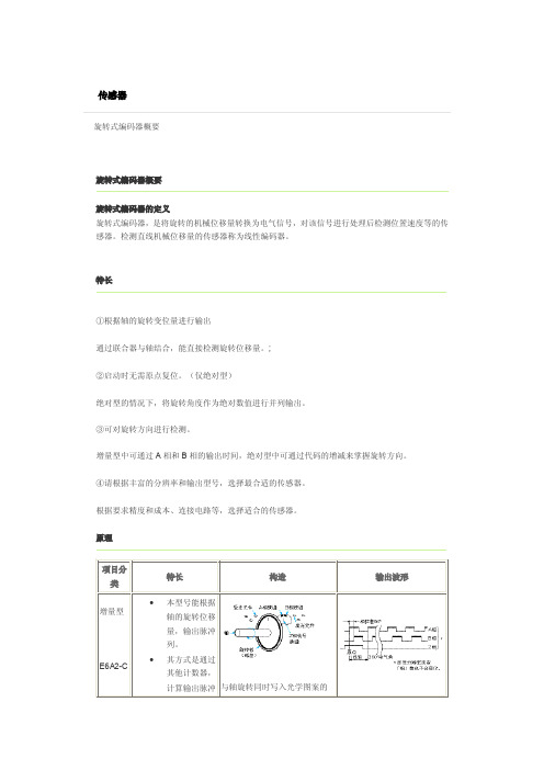
项目
特长
构造
输出波形
·本 型 号 能 根 据 轴 的 旋 转 位 移 量,
输出脉冲列。
其方式是通过其他计数器,计算输
ফܗܝӊ AⳌ⣁㓱 BⳌ⣁㓱
出脉冲数,通过计数检测旋转量。
·希望知道某输入轴位置的旋转量, 先按基准位置,使计数位的计数 值复位,然后再用计数器把由该 䕈 位置发出的脉冲数累加起来。
E6B2系列编码器接线方法
1
欧姆龙E6B2系列(增量型编码器)接线方式
常用欧姆龙E6B2系列编码器有CWZ6C 、CWZ5B 、CWZ3E 三种,其中CWZ6C 和CWZ5B 分别是NPN 开路集电极和PNP 开路集电极输出(如下图),CWZ3E 是电压输出,因此在接线上前2
者不同与以往编码器,不能直接接入变频器的脉冲采集装置中,以安川PG-2卡为例:
一:根据三极管放大电路,在基极与电源间增加偏置电阻接法
2 其中R取值680欧~2000欧,
其中针对安川PG-B2卡应选用680~1000欧的电阻
针对ABB PRBA01编码器模块应选用 15V(1000~1500欧),24V(1500~2000欧)的电阻
(ABB只能用偏置电阻接法,且A-B-不能同OV短接,出差前注意带电阻。
)
若出现下列情况,则适当减少电阻阻值:
A:脉冲信号不稳定,编码器反馈数值波动较大
B:正方向信号反馈数值正常,负方向反馈数值基本没有
C:反馈数值响应慢,电机运行电流不正常
二:直连法
此接法经过实际运用信号正常,但有反映在超频下有可能发生异常,请在使用此连接方式时注意观察。
3。
omron编码器接线方法(行业二类)
文书#借鉴1欧姆龙E6B2系列(增量型编码器)接线方式常用欧姆龙E6B2系列编码器有CWZ6C 、CWZ5B 、CWZ3E 三种,其中CWZ6C 和CWZ5B 分别是NPN 开路集电极和PNP 开路集电极输出(如下图),CWZ3E 是电压输出,因此在接线上前2者不同与以往编码器,不能直接接入变频器的脉冲采集装置中,以安川PG-2卡为例:一:根据三极管放大电路,在集极与电源间增加偏置电阻接法PG-2+12V 0V A+A-B+B-E6B2-CWZ6C+-A BZRPG-2+12V 0V A+A-B+B-E6B2-CWZ5B+-A BZR文书#借鉴2其中R 取值680欧~2000欧,0.5W其中针对安川PG-B2卡应选用680~1000欧的电阻针对ABB PRBA01编码器模块应选用 15V (1000~1500欧),24V (1500~2000欧)的电阻(ABB只能用偏置电阻接法,且A-B-不能同OV 短接,出差前注意带电阻。
)若出现下列情况,则适当减少电阻阻值: A :脉冲信号不稳定,编码器反馈数值波动较大 B :正方向信号反馈数值正常,负方向反馈数值基本没有 C :反馈数值响应慢,电机运行电流不正常 二:直连法PG-2 +12V 0V A+A-B+B-E6B2-CWZ6C+-A BZPRBA01 +15V0V A+A-B+B-E6B2-CWZ6C+-A BZR文书#借鉴 3此接法经过实际运用信号正常,但有反映在超频下有可能发生异常,请在使用此连接方式时注意观察。
PG-2+12V 0V A+A-B+B-E6B2-CWZ5B+-A BZ。