单轴拉伸
岩石单轴压缩、拉伸、巴西劈裂数值实验模拟

2.1 软件的基本原理
RFPA 是一个以弹性力学为应力分析工具、以弹性损伤理论及其修正后的 Coulomb 破坏准则为介质变形和破坏分析模块的真实破裂过程分析系统。 其基本 思路是: 1)材料介质模型离散化成由细观基元组成的数值模型,材料介质在细观上 是各向同性的弹-脆性或脆-塑性介质; 2)假定离散化后的细观基元的力学性质服从某种统计分布规律(如 weibull 分布),由此建立细观与宏观介质力学性能的联系; 3)按弹性力学中的基元线弹性应力、应变求解方法,分析模型的应力、应 变状态。RFPA 利用线弹性有限元方法作为应力求解器; 4)引入适当的基元破坏准则(相变准则)和损伤规律,基元的相变临界点 用修正的 Coulomb 准则; 5)基元的力学性质随演化的发展是不可逆的; 6)基元相变前后均为线弹性体; 7)材料介质的裂纹扩展是一个准静态过程,忽略因快速扩展引起的惯性力 的影响。
2.2 软件的网格划分
RFPA 选取等面积四节点的四边形单元剖分计算对象。为了使问题的解答足 够精确,RFPA 方法要求模型中的单元足够小(相对于宏观介质),以能足够精
确的地反映介质的非均匀性。但它又必需足够大(包含一定数量的矿物和胶结物 颗粒,以及微裂隙、孔洞等细小缺陷),因为作为子系统的单元实际上仍是一个 自由度很大的系统,它具有远大于微观尺度的细观尺度。这以要求正是为了保证 使剖分后的单元性质尽量接近基元性质。尽管这样会增加计算量,但是问题的处 理变得简单, 而且随着计算机技术的高速发展, 计算机瓶颈的影响将会逐渐消除。 由于模型中的基元数量足够多,宏观的力学行为,本质上是介质大量基元力学行 为的集体效应。
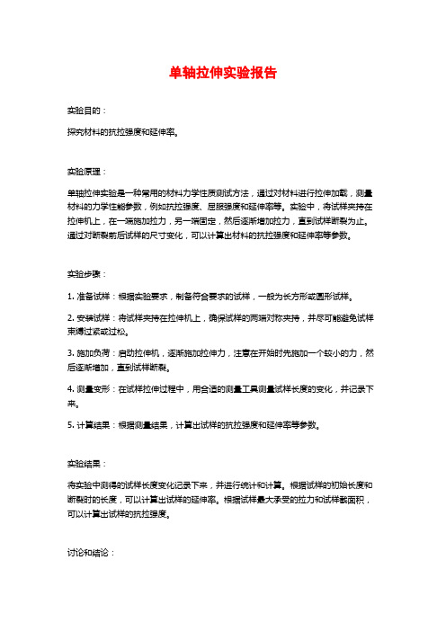
(a)step42-01
(b)step52-02
(c)step70-06
图 3、RFPA 模拟单轴拉伸条件下的破坏过程、最大主应力场、声发射累计分布图
混凝土单轴直接拉伸受力分析

混 凝 土 单轴 直 接 拉 伸 受 力分 析
黄 俊 , 弘道 姜
20 9 ) 10 8 ( 河海 大学 土木工程学院 , 江苏 南 京
摘 要 : 3种直接 拉 伸试验 方式 ( 对 内埋 式 、 夹式和 粘贴 式 ) 外 下混凝 土试 件各 点 的应 力分布 状 况进 行
了有 限元数 值 分析 , 获得 混凝 土单 轴 直接 拉 伸 应 力 一 变全 曲线 所 需 的条 件进 行 了探 讨 , 对 试 对 应 并
件在 两端粘 贴 受力方 式 下辅 以刚性 架装 置后 刚性 架拉 杆 刚度 、 置对 试件 受 力 的影 响进 行 了研 究 . 位
结果 表 明 : 两端粘 贴加 载 方式 可使 试 件各 点应 力 分 布更 加 均 匀 , 力集 中程 度 较 低 ; 小 刚性 架 的 应 减 高度 、 大刚 性 架的截 面积 有利 于获得 完整 的应 力一 变全 曲线 . 增 应
维普资讯
第3 4卷第 3期
2O 0 6年 5月
河 海 大 学 学 报 (自 然 科 学 版 ) Junl f oa U i rt( a rl c ne) ora o hi n e i N t a Si cs H v sy u e
V 1 3 . o .4 No 3
型 0 1 0l .6
0 1 00 .6
, ,
0 l 99 5
.
・ , ●
0
0. 0 0 0 0 0 0 0 0 0l . 2 . 3 .4 .5
节 点位 置 / m
20 P , 1 G a泊松 比为 0 35 混 凝 土 的弹 模 为 2 P , 松 比为 .1; 1 a泊 G
关键 词 : 混凝 土 ; 直接拉 伸 ; 力分析 ; 应 刚性 架
常温单轴拉伸实验、压缩实验、扭转实验

实验1 常温单轴拉伸实验马 杭 编写单轴拉伸实验是研究材料机械性能的最基本、应用最广泛的实验。
由于试验方法简单而且易于得到较为可靠的试验数据,在工程上和实验室中都广泛利用单轴拉伸实验来测取材料的机械性能。
多数工程材料拉伸曲线的特性介于低碳钢和铸铁之间,但其强度和塑性指标的定义与测试方法基本相同,因此通过单轴拉伸实验分析比较两种材料的拉伸过程,测定其机械性能,在机械性能的试验研究中具有典型的意义,掌握其拉伸和破坏过程的特点有助于正确合理地认识和选用材料,了解静载条件下结构材料的许用应力的内涵。
一、实验目的1.通过单轴拉伸实验,观察分析典型的塑性材料(低碳钢)和脆性材料(铸铁)的拉伸过程,观察断口,比较其机械性能。
2.测定材料的强度指标(屈服极限S σ、强度极限b σ)和塑性指标(延伸率δ和面缩率ψ)。
二、实验设备1.电子万能材料试验机WDW-100A(见附录一)。
2.计算机、打印机。
3.游标卡尺。
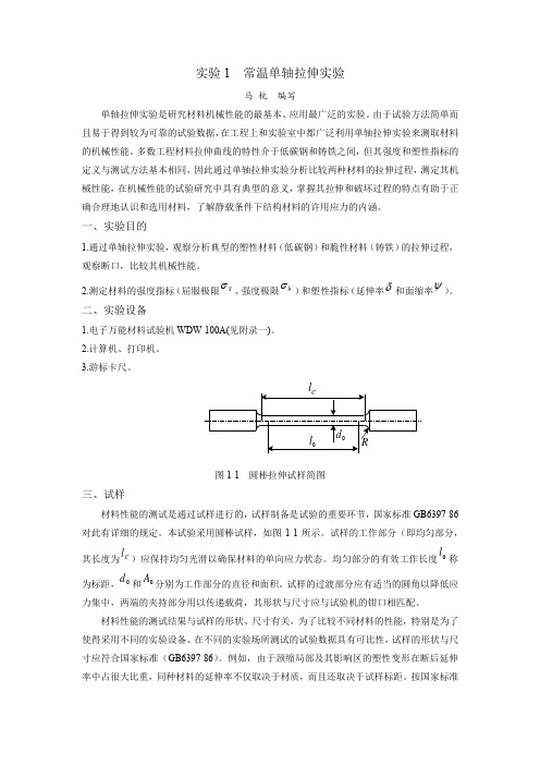
图1-1 圆棒拉伸试样简图三、试样材料性能的测试是通过试样进行的,试样制备是试验的重要环节,国家标准GB6397-86对此有详细的规定。
本试验采用圆棒试样,如图1-1所示。
试样的工作部分(即均匀部分,其长度为C l )应保持均匀光滑以确保材料的单向应力状态。
均匀部分的有效工作长度0l 称为标距,0d 和0A 分别为工作部分的直径和面积。
试样的过渡部分应有适当的圆角以降低应力集中,两端的夹持部分用以传递载荷,其形状与尺寸应与试验机的钳口相匹配。
材料性能的测试结果与试样的形状、尺寸有关,为了比较不同材料的性能,特别是为了使得采用不同的实验设备、在不同的实验场所测试的试验数据具有可比性,试样的形状与尺寸应符合国家标准(GB6397-86)。
例如,由于颈缩局部及其影响区的塑性变形在断后延伸率中占很大比重,同种材料的延伸率不仅取决于材质,而且还取决于试样标距。
按国家标准规定,材料延伸率的测试应优先采用两类比例试样:(1)长试样:0010d l =(圆形截面试样),或003.11A l =(矩形截面试样) (2)短试样:005d l =(圆形截面试样),或0065.5A l =(矩形截面试样)用长试样和短试样测得的断后延伸率分别记做10δ和5δ,国家标准推荐使用短比例试样。
单轴拉伸实验报告
单轴拉伸实验报告实验目的:探究材料的抗拉强度和延伸率。
实验原理:单轴拉伸实验是一种常用的材料力学性质测试方法,通过对材料进行拉伸加载,测量材料的力学性能参数,例如抗拉强度、屈服强度和延伸率等。
实验中,将试样夹持在拉伸机上,在一端施加拉力,另一端固定,然后逐渐增加拉力,直到试样断裂为止。
通过对断裂前后试样的尺寸变化,可以计算出材料的抗拉强度和延伸率等参数。
实验步骤:1. 准备试样:根据实验要求,制备符合要求的试样,一般为长方形或圆形试样。
2. 安装试样:将试样夹持在拉伸机上,确保试样的两端对称夹持,并尽可能避免试样束缚过紧或过松。
3. 施加负荷:启动拉伸机,逐渐施加拉伸力,注意在开始时先施加一个较小的力,然后逐渐增加,直到试样断裂。
4. 测量变形:在试样拉伸过程中,用合适的测量工具测量试样长度的变化,并记录下来。
5. 计算结果:根据测量结果,计算出试样的抗拉强度和延伸率等参数。
实验结果:将实验中测得的试样长度变化记录下来,并进行统计和计算。
根据试样的初始长度和断裂时的长度,可以计算出试样的延伸率。
根据试样最大承受的拉力和试样截面积,可以计算出试样的抗拉强度。
讨论和结论:根据实验结果,可以分析材料的力学性能,例如材料的延伸性、强度等。
通过比较不同材料的实验结果,可以评估材料的质量和适用性,为相关工程应用提供依据。
安全注意事项:1. 实验过程中应注意操作规程,确保实验过程的安全。
2. 实验时应注意加强照明,以避免因疏忽而引起的意外事故。
3. 对于可能具有挥发性、腐蚀性或有毒性的材料,应采取相应的安全防护措施,如佩戴防护手套、眼镜等。
实验设备和试剂:1. 拉伸机:用于施加拉力和测量力学参数。
2. 试样:用于实验的材料样品。
3. 尺规:用于测量试样长度的变化。
实验结果记录表:试样编号初始长度(mm)断裂时长度(mm)抗拉强度(MPa)延伸率(%)12345备注:每个试样的实验结果都应进行独立记录和计算,并统计出平均值和标准偏差等参数。
JSCE单轴拉伸测试标准

Testing Method 1: Preparation of Specimens for Strength Tests1.1 ScopeThis standard prescribes the method of producing mold-cast specimens for compressive strength and uniaxial tension tests on High Performance Fiber Reinforced Cement Composites with Multiple Fine Cracks (HPFRCC).1.2 Referenced standardsThe following standards form a part of this standard through references herein. The latest versions of the standards should be applied for this purpose.JSCE-F505 Method of making mortar in the laboratory (in Japanese)JSCE-F506 Method of making mortar or cement paste cylindrical specimens for compressive strength tests (in Japanese)JSCE-F551 Method of making steel fiber reinforced concrete in the laboratory (in Japanese)JIS A 1115 Method of sampling fresh concreteJIS A 1132 Method of making and curing concrete specimensJIS A 1138 Method of making test samples of concrete in the laboratory1.3 HPFRCC samplesHPFRCC should be sampled as follows.a) When producing HPFRCC specimens in the laboratory, provisions of JIS A 1138, JSCE-F505or JSCE-F551 should be applied to suit the HPFRCC material to be tested.b) JIS A 1115 should be followed when sampling HPFRCC from mixers, hoppers, concretebucket or placed concrete.c) Sprayed HPFRCC should be sampled on sites or from sprayed HPFRCC on form panels, etc.,or directly from the same material as those adopted in the spray.1.4 Number of specimensThe number of specimens should be as follows.a) Three or more for compressive tests, andb) Five or more for direct uniaxial tension tests.1.5 Specimens for compression tests1.5.1 Dimensions of specimensSpecimens should be cylindrical having a height twice the size of the diameter. The diameter should be determined pursuant to JIS A 1132 or JSCE-F 506.1.5.2 Specimen production apparatusSpecimens should be produced as follows.a) Molds should be cylindrical, made of a non-water-absorbing material resistant to cement such as metal or plastic.b) Molds should be free from deformation or water leakage during production of specimens,c) Molds should be designed to ensure the precision required for the specimen to be produced.d) Appropriate form release agent or mineral oil may be applied on the internal surfaces of the molds.e) When compacting with a mallet, the mallet should have weight and dimensions sufficient for ensuring adequate compaction for the target HPFRCC.f) When compacting with a vibration table, the table should have performance sufficient for ensuring adequate compaction for the target HPFRCC.g) The capping plate should be a polished glass or a polished steel plate thicker than 6mm having a size at least 25mm greater than the diameter of the mold.1.5.3 Production of specimens1.5.3.1 Using a malletSpecimens should be produced in the same procedures (e.g. placement and spraying methods) as in the actual work, and the use of an internal vibrator is prohibited. During placement, the material should be filled into the mold without pausing to minimize the production of air voids. To compact the material filled, the sides of the mold should be tapped with a mallet to reduce air voids and create a smooth surface.1.5.3.2 Using a vibration tableSpecimens should be produced in the same procedure (e.g. placement and spraying methods) as applied in the actual work, and the use of an internal vibrator is prohibited. During placement, the material should be filled into the mold without pausing to minimize the formation of air voids. To reduce air voids, the mold should be stuck tightly to the vibration table to apply vibration for compaction. The duration of compaction should be determined according to the properties of the target HPFRCC and to the performance of vibrator to ensure adequate compaction. Care should be taken for the duration of compaction not to cause materials segregation.1.5.3.3 Compaction at the top layerThe material should be filled to the top rim of the mold allowing the top face of HPFRCC after compaction becomes slightly below the top rim. Where the end face of the specimen is subject to polish finishing, the top level of compacted HPFRCC should be made slightly above the top of the mold.1.5.4 Top surface finishing of specimens1.5.4.1 Capping specimensCapping of specimens should be performed as follows.a) The capping material should have good adhesion to HPFRCC without harmful effects.b) The compressive strength of the capping layer should not be lower than the expected compressive strength of HPFRCC.c) The capping layer should be made as thin as possible.d) The timing of capping should be determined according to the setting time, test purpose and age at the time of the test of the HPFRCC tested. When capping the specimen before demolding, it should be done at an appropriate timing between 2 and 48 hours after placement.1.5.4.2 When giving polish finishingWhere the top surface is subject to polish finishing, it should be done without affecting the HPFRCC tested.1.5.5 Permissible dimensional errors of specimensPermissible dimensional errors of specimens should be pursuant to JIS A 1132.1.6 Specimens for uniaxial tension tests1.6.1 Dimensions of specimensDimensions of specimens should be pursuant to Fig.T1.6.1 and Table T1.6.1. Note that these criteria should be applied only to those specimens whose minimum size is at least the fiber length and twice the maximum aggregate size. For other specimens, a relevant uniaxial tensile test method should be established separately and the specimens should be produced based on that method.1.6.2 Specimen production apparatusThe following provisions should be applied to apparatus for specimen production:.a) Molds should be made of non-water-absorbing materials and resistant to cement such asmetal or plastics.b) Molds should be free from deformation and water leakage during production of specimens.c) Molds should be designed to ensure the precision required for the specimen to be produced.d) Appropriate form release agent or mineral oil may be applied on the internal surfaces ofmolds.e) When compacting with a mallet, the mallet should have a weight and dimensions capable ofensuring adequate compaction for the target HFRCC.f) When compacting with a vibration table, the table should have performance capable ofensuring adequate compaction for the target HFRCC.1.6.3 Production of specimens1.6.3.1 Using a malletSpecimens should be produced in the same procedures (e.g. placement and spraying methods) as applied in the actual work, and the use of a tamping rod or an internal vibrator is prohibited. During placement, the material should be filled into the mold from a single direction without pausing to minimize entrapped air, and placement on the hardened material should be avoided. To compact the material filled, the sides of the mold should be hit with a mallet to reduce air voids and creating a smooth surface.1.6.3.2 Using a vibration tableSpecimens should be produced in the same procedures (e.g. placement and spraying methods) as applied in the actual work, and the use of a tamping rod or an internal vibrator is prohibited. During placement, the material should be filled into the mold from a single direction at one time to minimize entrapped air, and placement on the hardened material should be avoided. To reduce air voids, the mold should be stuck tightly to the vibration table to have enough vibration for compaction. The duration of compaction should be determined according to the properties of target HPFRCC and performance of vibrator ensuring adequate compaction. Care should be taken for excessive duration of compaction to avoid segregation of materials.1.6.4 Permissible dimensional errors of specimensPermissible dimensional errors of specimens should be pursuant to Table T1.6.1.Fig. T1.6.1 Specimen for uniaxial tensile strength testTable T1.6.1 Dimensions and permissible errors of specimens for uniaxial tensile strength test (Unit:mm)Parallel portion width Original reference pointdistanceParallel portionlengthThicknessSize30808013 or 30 Permissible error±1±1±1±11.7 Demolding and curingDemolding and curing should be as follows.a) Molds should be removed between 24 and 48 hours after placement.b) After casting, specimens should be properly treated, e.g. by covering their top surface with glass plates until demolding.c) After casting, specimens should be cured according to the specific test purpose.Testing Method 2: Testing Method of Uniaxial Tensile Strength2.1 ScopeThis standard prescribes the method of evaluating the tensile yield strength, tensile strength and ultimate tensile strain of High Performance Fiber Reinforced Cement Composites with Multiple Fine Cracks (HPFRCC) by uniaxial tension tests.2.2 Referenced standardThe standard cited below forms a part of this standard through herein referenced. The latest version of referenced standard should be applied.Testing Method 1: Preparation of specimens for strength tests.2.3 ApparatusTesting machines and apparatus should be as follows.a) The testing machine for the tensile test should be of Grade 1 of JIS B 7721 or higher and should allow displacement-controlled loading.b) The test machine should ensure the allignment between chucks be properly vertical.c) The apparatus measuring the displacement between reference points should have a precision of 1/1000mm or higher and not restrict any deformation between the reference points.d) The chucking mechanism should fit to the specimen shape and test load, and is designed to allow tensile loading along the specimen’s central axis. The specimen should be placed in the test machine with a chuck on both ends, a fixed support on one end and a pin (hinge) support on the other end.Fig. T2.3.1 Outline of uniaxial tension testAs examples of chucking mechanism, test machines with a pneumatic chuck and clamp jigs are shown in Figs. T2.3.2 and T2.3.3.Hinge(a) Fixed load end(b) Pin supported load endFig. T2.3.2 Example of pneumatic chucking mechanismHinge(a) Fixed load end(b) Pin supported load endFig. T2.3.3 Example of clamp-jig chucking mechanism2.4 SpecimensThe shape, dimensions and production method of specimens should be pursuant to those specified for uniaxial tensile tests prescribed in “Testing Method 1: Preparation of specimens for strength tests”.2.5 Test methodTests should be carried out as follows.a) The load should be applied using a chucking mechanism suited to the shape of the specimen. Figure T2.5.1 shows test conditions with different chucking mechanisms.b) The load should be applied at a constant specimen deformation rate of approximately 0.5mm per minute.c) At least five specimens should be tested.(a) Pneumatic chucking mechanism (b) Chucking mechanism using clamp jigsFig. T2.5.1 Example of tests with different chucking mechanisms2.6 CalculationThe initial sectional area of the test zone, reference point distance, yielding point, tensile yield strength, ultimate tensile strain, maximum stress in the strain-hardening region and tensile strength should be obtained in the following procedure:a) The initial sectional area of the test zone is obtained as the mean value of three sections at both ends and the center of the reference points.b) The reference point distance should be measured with a proper measuring instrument. c) The test value of tensile yield strength f tyi (N/mm 2) is given byty tyi F f A =(T2.6.1)where,F ty : Load at the yielding point (1) (N)A 0: Initial sectional area of test zone of specimen (mm 2)Note (1) Yielding point: A point representing the minimum load, which is found between theinitial cracking point and the softening starting point (2) on the line joining convex inflection points, where stress changes from increase to decrease, in the stress-strain relationship obtained in tensile tests on specimens.Note (2) Softening starting point: In a direct uniaxial tension test on HPFRCC, the tensileload shows a gradual increase after the initial cracking accompanied by the development of multiple micro cracks. After these multiple micro cracks develop, the tensile stress decreases rapidly showing an increase in width of certain cracks. The point at which the load starts reducing associated with the increase in crackwidth is defined as the “softening starting point”. In the stress-strain relationship obtained in tensile tests on specimens, the softening starting point is an inflection point immediately before the stress finally stops increasing.d) The test value of maximum stress in the strain-hardening region f pshi (N/mm 2) is given bypsh pshi F f A =(T 2.6.2)where,F psh : Maximum load (N) in the strain region between the yielding point and softening starting point.e) The test value of tensile strength f ti (N/mm 2) is given bytti F f A =(T 2.6.3) where,F t : Maximum load (N)f) The strain at the softening starting point is defined as the ultimate tensile strain, whose test value εtui (%) is given byu tui l l l ε−=×100 (T2.6.4) where,I u : Reference point distance at the ultimate point (mm) I 0: Original reference point distance (mm)Tensile yield strengthTensile strengthLine between inflection pointsT e n s i l e s t r e s s (N /m m 2)T ensile strainUltimate tensile strainStandard tensile yield strength f tynFig. T2.6.1 Yielding point, ultimate point and tensile strengthg) The tensile yield strength, ultimate tensile strain, maximum stress in the strain-hardening region and tensile strength are derived from the mean values of 3 or more specimens excluding those that showed the maximum and minimum ultimate tensile strain. However, allthe results of tests performed should be used for calculating dispersion, such as the coefficient of variation for the tensile yield strength, ultimate tensile strain, maximum stress in the strain-hardening region and tensile strength.2.7 ReportingReports should include necessary subjects among the following:a) Date/month/year of the testsb) Specimen symbolsc) Width and thickness of the parallel portion of test zone of specimens (mm)d) Date of specimen production and material age of the specimense) Maximum load (N)f) Tensile yield strength (N/mm2)g) Maximum stress in the strain-hardening region (N/mm2)h) Tensile strength (N/mm2)i) Ultimate tensile strain (%)。
基于数字图像相关方法的Q235_钢单轴拉伸变形研究

基于数字图像相关方法的Q235钢单轴拉伸变形研究肖汉斌1 陈 田1 于家硕1 裴雪冬1 李占峰21武汉理工大学交通与物流工程学院 武汉 430063 2大连港散杂货码头公司技术工程部 大连 116001摘 要:数字图像相关(DIC)方法是一种非接触式的光学测量方法,通过高速摄像机记录实验过程,并基于计算机视觉技术对实验过程进行分析与数值计算,从而得出目标区域在实验过程中的应变变化情况。
Q235钢是起重机的常用材料,研究Q235钢在拉伸载荷下的变形对保证起重机结构安全有重要意义。
文中通过DIC技术对Q235钢试件拉伸变形过程进行研究,对比DIC方法分析值、应变片测量值以及有限元仿真模拟值。
结果表明,通过DIC 方法得到的分析值与其余两种方式得出的数据相对误差均小于5%,为DIC方法在金属结构拉伸变形研究中提供了有力参考。
关键词:金属结构;数字图像相关;拉伸变形;Q235钢;有限元仿真中图分类号:TP391:U653.921 文献标识码:A 文章编号:1001-0785(2022)16-0019-07Abstract: Digital image correlation (DIC) method is a non-contact optical measurement method. The experimental process is recorded by a high-speed camera, and the experimental process is analyzed and numerically calculated by computer vision technology, so as to obtain the strain change of the target area during the experimental process. Q235 steel is a common material for cranes. It is of great significance to study the deformation of Q235 steel under tensile load to ensure the structural safety of cranes. In this paper, the tensile deformation process of Q235 steel specimen is studied by DIC technology. By comparing the analysis value of DIC method, the measured value of strain gauge and the simulation value of finite element simulation, it can be found that the relative error between the analysis value obtained by DIC method and the data obtained by the other two methods is less than 5%, which provides a powerful reference for the application of DIC method in the research of tensile deformation of metal structures.Keywords:metal structure; digital image correlation; tensile deformation; Q235 steel; finite element simulation0 引言起重机被广泛运用于港口运输、机械等行业,由于其部分金属构件长期处于复杂的载荷条件下,其故障的产生与金属结构的加工工艺、现场环境和作业工况有很大关系,故应力应变是反映金属故障的重要指标[1]。
单轴拉伸曲线类型

单轴拉伸曲线类型
单轴拉伸是一种常见的试验方法,用于评估材料的机械性能。
在这种试验中,材料在一端被夹持,然后沿一个轴向应用拉力,以引起材料的延展。
通过测量材料的应力-应变关系,可
以确定材料的力学性能。
单轴拉伸试验产生的曲线通常可以分为几种类型。
首先是线性弹性阶段,当施加的拉力小于材料的屈服强度时,材料会呈现出线性弹性行为。
在这个阶段,应力和应变成正比,材料会完全恢复原始形状,一旦去除拉力。
然后是屈服点之后的塑性阶段,材料开始产生可见的塑性变形。
应力-应变曲线在这个阶段会
发生明显的曲线弯曲,而不再是线性关系。
材料在应变增加时会继续变形,即使拉力降低或保持恒定。
最后是断裂阶段,在某个应变点后,材料会发生断裂。
此时,曲线会急剧下降,表明材料失去了抵抗拉伸的能力。
断裂点依赖于材料的强度和韧性,不同材料的断裂点位置可能会有所不同。
除了这些基本类型之外,还可能出现其他类型的曲线,取决于材料的特性和应变速率。
例如,某些材料可能会显示出颈缩现象,即在拉伸过程中出现局部收缩和变细的现象。
这种现象通常发生在高强度金属材料中,逐渐增加的应变会导致局部失稳。
总的来说,单轴拉伸曲线类型提供了对材料力学性能的重要信息。
了解和分析这些曲线有助于工程师和材料科学家了解材料的性能,并进行合理的设计和选择。
常温单轴拉伸实验
实验1 常温单轴拉伸实验马 杭 编写单轴拉伸实验是研究材料机械性能的最基本、应用最广泛的实验。
由于试验方法简单而且易于得到较为可靠的试验数据,在工程上和实验室中都广泛利用单轴拉伸实验来测取材料的机械性能。
多数工程材料拉伸曲线的特性介于低碳钢和铸铁之间,但其强度和塑性指标的定义与测试方法基本相同,因此通过单轴拉伸实验分析比较两种材料的拉伸过程,测定其机械性能,在机械性能的试验研究中具有典型的意义,掌握其拉伸和破坏过程的特点有助于正确合理地认识和选用材料,了解静载条件下结构材料的许用应力的内涵。
一、实验目的1.通过单轴拉伸实验,观察分析典型的塑性材料(低碳钢)和脆性材料(铸铁)的拉伸过程,观察断口,比较其机械性能。
2.测定材料的强度指标(屈服极限、强度极限)和塑性指标(延伸率和面缩率)。
二、实验设备1.电子万能材料试验机WDW -100A(见附录一)。
2.计算机、打印机。
3.游标卡尺。
图1-1 圆棒拉伸试样简图 三、试样材料性能的测试是通过试样进行的,试样制备是试验的重要环节,国家标准GB6397-86对此有详细的规定。
本试验采用圆棒试样,如图1-1所示。
试样的工作部分(即均匀部分,其长度为)应保持均匀光滑以确保材料的单向应力状态。
均匀部分的有效工作长度称为标距,和分别为工作部分的直径和面积。
试样的过渡部分应有适当的圆角以降低应力集中,两端的夹持部分用以传递载荷,其形状与尺寸应与试验机的钳口相匹配。
材料性能的测试结果与试样的形状、尺寸有关,为了比较不同材料的性能,特别是为了使得采用不同的实验设备、在不同的实验场所测试的试验数据具有可比性,试样的形状与尺寸应符合国家标准(GB6397-86)。
例如,由于颈缩局部及其影响区的塑性变形在断后延伸率中占很大比重,同种材料的延伸率不仅取决于材质,而且还取决于试样标距。
按国家标准S σb σδψC l 0l 0d 0A规定,材料延伸率的测试应优先采用两类比例试样:(1)长试样:(圆形截面试样),或(矩形截面试样) (2)短试样:(圆形截面试样),或(矩形截面试样) 用长试样和短试样测得的断后延伸率分别记做和,国家标准推荐使用短比例试样。
- 1、下载文档前请自行甄别文档内容的完整性,平台不提供额外的编辑、内容补充、找答案等附加服务。
- 2、"仅部分预览"的文档,不可在线预览部分如存在完整性等问题,可反馈申请退款(可完整预览的文档不适用该条件!)。
- 3、如文档侵犯您的权益,请联系客服反馈,我们会尽快为您处理(人工客服工作时间:9:00-18:30)。
单轴拉伸实验报告
使用设备名称与型号 同组人员 实验时间
一、实验目的
1.通过单轴拉伸实验,观察分析典型的塑性材料(低碳钢)和脆性材料(铸铁)的拉伸过程,观察断口,比较其机械性能。
2.测定材料的强度指标(屈服极限S σ、强度极限b σ)和塑性指标(延伸率δ和面缩率ψ)。
二、实验设备与仪器
1.电子万能材料试验机WDW-100A(见附录一)。
2.计算机、打印机。
3.游标卡尺。
三、实验原理
单轴拉伸实验在电子万能材料试验机上进行。
在试验过程中,试验机上的载荷传感器和位移传感器分别将感受到的载荷与位移信号转变成电信号送入EDC 控制器,信号经过放大和模数转换后送入计算机,并将处理过的数据同步地显示在屏幕上,形成载荷—位移曲线(即l P ∆-曲线),试验数据可以存储和打印。
在实验前,应进行载荷传感器和位移传感器的标定(校准)。
根据l P ∆-曲线和试样参数,计算材料的各项机械性能指标。
根据性能指标、
l P ∆-曲线特征并结合断口形貌,分析、评价材料的机械性能。
试验机操作软件的使用可参见附录一。
四、实验操作步骤
1.原始尺寸测量:(1)确定标距0l 。
(2)测量直径0d :在标距中央及两条标距线附近各取一截面进行测量,每截面沿互相垂直方向各测一次取平均值,0d 采用三个截面中的平
均值的最小值。
2.初始条件设定:如图1-2,(1)首先进行载荷与位移清零,用鼠标点击载荷与位移(绿色)显示区右上方的0.0按纽,使两者的显示值均为零。
(2)点击左上方“曲线参数”,根据材料的强度与塑性,选择合适的显示量程。
图二右下方为载荷—位移曲线的显示区,其X轴为横梁位移(mm),Y轴为载荷(kN)。
(3)点击左上方“试样信息”,输入试样参数。
3.试样装夹:(1)选择“手动操作”,设定较快的横梁移动速度(20mm/min或50mm/min),点击“上升”或“下降”使横梁移动并观察。
当横梁到达合适的位置时,点击“停止”使横梁停止移动。
(2)将试样的夹持端插入上楔形夹头并旋紧,点击“下降”使试样的另一端插入下楔形夹头,下降时注意对中以免产生碰撞,停机后旋紧下夹头。
注意,试样装夹之后不再进行载荷清零。
图1-2 拉伸试验的计算机界面
4.加载试验:(1)选择“手动操作”,设定试验速度,建议低碳钢试样设为5mm/min,铸
铁试样设为1-2mm/min。
(2)点击“上升”开始拉伸试验,注意观察试样、曲线显示区的曲线以及载荷与位移显示值的变化。
(3)低碳钢试样将依次出现变形的四个阶段。
当载荷从最大值开始下降时可以看到试样的颈缩区,如果试样表面光滑、材料杂质含量少,可以清楚地看到表面45°方向的滑移线。
试样断裂后试验机自动停止加载。
5.试验结束前的重要工作:(1)打印记录曲线,开启打印机电源后,依次点击右上角“分析”(弹出新界面)、“打印”。
点击右上角“保存”,可以将本次试验的信息以文本文件的形式保存起来,文件名的后缀为“.dat”。
(2)取下试样,对拢已破坏的试样,测量有关数据,观察断口形貌。
五、实验结果及分析计算
1、实验数据(可附实验曲线)
2、 结果计算 1.强度指标计算:
(1)屈服极限 0/A P S S =σ (MPa ) (2)强度极限 0/A P b b =σ (MPa )
屈服载荷S P 取屈服平台的下限值。
b P 取l P ∆-曲线上的最大载荷(参见图三)。
脆性材料不存在屈服阶段,所以只需计算b σ。
2.塑性指标计算:
(1)延伸率
%1000
1⨯-=
l l l δ (2)面缩率 %1000
1
0⨯-=
A A A ψ
六、思考题
1、 分析比较低碳钢和铸铁在拉伸时的机械性能、变形、强度、破坏方式等。
2、本实验的力—位移曲线上的变形量与试件上的变形量是否相同?如果要利用力—
位移曲线来近似确定试样的断后延伸率,应该怎样做?
3、为什么要采用比例试样?同一材料的δ10和δ5有何关系?
七、实验中的收获、感想与建议。