日机装圣达因高速泵操作维修手册SndPump-LMV-322-IOM
高速泵操作手册(改)
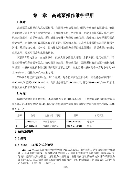
第一章高速泵操作维护手册1.概述高速泵的工作原理与离心泵相同,使用维护和故障处理方面与普通的离心泵类似,他比普通的离心泵多增设有齿轮增速器。
主要由泵机组、增速装置、润滑及监控系统、底座及电机等部分组成,由于转速高,所以增速齿轮材料均经过渗碳处理,高速轴上的轴承采用巴氏合金轴承,它们运转时必须经过良好的润滑,泵启动之前,先启动主油泵给油加压进行强制润滑,然后起动电机,运转时,齿轮箱的润滑油压力应保持规定范围内,油温应保持在规定范围之间,温度可用冷却水量来调节。
该泵具有结构紧凑、占地面积小,能够实现小流量大扬程,维护方便、适用范围广、可靠性好及使用寿命长等优点。
缺点是易出故障,维修费用高. 通常所说的高速泵一般指高速切线泵,一般在流量较小而扬程很高的情况下会选用,流量范围一般在几个立方每小时到100立方每小时,扬程在200~1000米之间。
BGMA联合罐区高速泵共4台,共2个位号,每个位号两台互相备用。
不合格裂解碳四泵AP-3104A/B,型号GSB-L2-10/210,汽油组分输送泵AP-3211A/B,型号GSB-W4A-12/110,厂家北京航天石化技术装备工程公司。
2.用途BGMA联合罐区高速泵共4台,不合格碳四泵AP-3104A/B是将不合格裂解碳四送回新裂解装置回炼,汽油组分泵AP-3211A/B是将汽油组分送至新裂解装置做为裂解气压缩机洗油,具体明细见下表3.结构及原理3.1结构3.1.1GSB − L2型立式高速泵GSB −L2型立式高速泵为单级单吸部分流式离心泵,由电动机、齿轮增速箱(一级增速)、泵及其附件组成。
泵本体采用径向剖分、单级开式叶轮的悬臂结构,轴端装设诱导轮以提高泵抗汽蚀性能。
齿轮箱为一级增速。
齿轮箱内齿轮及轴承的润滑均采用压力油润滑方式,压力油是由装在低速轴端的油泵产生的,经过滤器、换热器后对各润滑点进行润滑。
(详见图一、图二)。
图二GSB-L2高速泵剖面图3.1.2GSB-W4A型卧式高速泵GSB-W4A型卧式高速泵为单级单吸小型部分流式离心泵,它具有结构小巧紧凑、性能优良、可靠性高的特点。
SDD手动泵说明书-2(不带换向)

SSD系列双级手动油泵使用说明书德州高科力液压有限公司地址:山东德州经济开发区金凤凰大酒店东200米电话:(0534)2755266 2754936S S D系列双级手动油泵使用保养说明书SSD系列双级手动油泵是一种新型超高压手动油泵,是我所获得国家专利产品(专利号ZL99 2 15386.7)。
本产品具有欧式风格的工业化设计外形,美观、大方,具有特殊的油路,独有的减功机能,可大大的提高工作效率,减轻操作力。
同时还预备压力表接口。
它在配备工具油缸或各种专用机具的情况下,可实现起重、弯曲、校直、挤压、压装、拉伸等工作需要。
同时,它还可以装置在其他机械设备中,作为液压动力部件,也可以作为各种中、高、超高压液压元件、高压容器,高压胶管的试压用泵,它款式多种,规格齐全,还有其变形产品双泵头油泵。
用户可根据不同的工作需要选择单向泵或双向泵,油箱的大容量或小容量。
可广泛用于矿山、铁路、建筑、工厂和科研部门。
一、主要技术参数(附表1)二、主要结构与作用SSD系列双级手动油泵由一个总吸油阀、吸排油阀、总排油阀完成吸、排油工作。
低压泵的压力由液控溢流阀调定,当泵压力达到液控溢流阀压力时,低压泵无载回油,从而减少了操作者的手压力。
它既提高了泵的流量和压力,同时也减少了对泵的保压、容积效率有影响的因素,所以,它既简化了结构又提高了可靠性。
双级手动油泵主要由以下几部分组成:1、泵体部分;2、手柄部分;3、储油箱。
(详见外形图附图一和工作原理图附图二)三、工作原理双级手动泵工作原理(见原理图)。
手动泵工作时,操作压杆8,带动双联柱塞7作往复运动。
当柱塞上行时,低压泵腔9和高压泵腔10形成真空,油液被吸入,当柱塞下行时,低压泵腔9和高压泵腔10的油液一同被排出总排油泵1。
当压力高于卸荷溢流阀4调定的压力时,卸荷阀开启,低压泵腔9的油液通过卸荷阀直接回油,此时只高压泵腔工作。
四、使用及注意事项1、双级泵的使用:①检查油箱油量,必要时补充液压油,油液推荐使用32#或46#液压油。
台恩耐 高粘度无堵塞转子泵浦安装、操作和维护说明书
1高粘度无堵塞转子泵浦安装、操作和维护通读以下内容,我们都将受益!将本手册置于相关负责人员手中并实施是雇主的责任!2重要安全信息本手册中所有安全警告和指示说明。
买方有责有加了垫片的固件,以防止由于垫片蠕变而引在维修之前,请切断电源并排净残料。
排放管中可能已加压。
必须卸载压力。
必须有应急处理方案。
良好,并且要确保在装配过程中对所有的螺栓拆卸前一定要冲洗干净。
在对泵进行维修之前,一定要确保压力已经完全从泵中、吸入口、排放口、管道和其他的开口和连接处卸载。
一定要切断电源,并使其处于不能运行的状态,以免在工作过程中启动。
所有在泵附近执行的操作过程警告警告收货检查 (4)存储 (4)特点 (5)性能 (6)应用领域: (6)结构; (12)工作原理:可通过改变电机转向,实现泵的正反转; (16)技术参数: (16)高粘度无堵塞转子泵浦与离心泵的比较 (17)高粘度无堵塞转子泵浦与单螺杆泵 (17)客户选型提醒 (18)3拆装维护 (19)操作规程 (20)拆卸前的准备 (21)日常维护 (21)记录(这是个好习惯) (21)常见故障与处理 (22)4收货检查¾ 在拆箱之前应记录原始状态和损害程度,照片对权利要求是有帮助的。
¾ 尽管我们在发货前已经做了仔细的检查,但是我们还是希望客户在收到货物时,能够再次仔细的检查。
按照你的购买定单核对,以保证得到正确的泵是为你准备的。
存储¾ 如您购买我们的产品,不是马上就使用,或者是做为备品存放的话。
那么应该把泵放在一个干燥且卫生的环境中。
经过了长时间的存放,那么在安装前应该把泵彻底的清洁。
润滑脂在某些情况下会变质。
特点¾可输送介质粘度为≤200万CP,以及含固量为60%的装料,输送流量范围广0.1‐3000m3/h¾超强的自吸能力,最大自吸9米¾双支撑更稳定,输出压力可达1.8Mpa¾无堵塞及多种转子形式,保证了不同物料的高通过率。
高速泵LMV313操作手册
目录1 安全说明 (1)1.1 设备安全预防措施 (1)1.2 测试设备 (1)1.3 化学品使用 (1)1.4 叉车作业 (2)1.5 电气安全 (2)1.6 防止坠落 (2)1.7 防机械伤害措施 (2)1.8 爆炸/火灾风险 (2)2.1 检查 (2)2.2 短期储存泵 (2)2.3 长期储存泵 (3)3 产品描述 (3)4 安装设施 (4)4.1 入口和出口管线 (4)4.2 泵体扩压腔排气 (4)4.3 密封环境控制系统 (4)4.4 液体缓冲系统 (5)4.5 垂直元件无支撑安装 (5)4.6 安装带有支撑的垂直元件 (5)4.7 底座安装元件 (6)4.8 驱动和耦合 (6)4.9 无垂直支撑的LMV元件的弹性联轴器 (6)4.10 驱动联轴器未安装 (6)4.11 润滑系统 (7)4.12 齿轮箱换热器 (8)4.13 油螺杆泵 (9)4.14 远距离换热器 (9)4.15 齿轮箱沉淀器 (9)4.16 齿轮箱换热器 (10)4.17 油滤器 (10)4.18 主润滑油泵及润滑油启动套件 (10)4.19 油压 (11)5 调试,启动,运转 (11)5.1 预调试 (11)5.1.1 熟知泵 (11)5.1.2 驱动器说明 (12)5.1.3 辅助系统的校对 (12)5.1.4 安装密封控制系统 (12)5.1.5 检查驱动器旋转 (12)5.1.6 管线连接 (12)5.2 预启动 (13)5.2.1 加压流体回路 (13)5.2.2 齿轮箱的维修 (13)5.2.3 辅助润滑油泵 (13)5.2.4 设置阀位 (13)5.3 运行条件 (13)5.3.1 确认运行条件 (13)5.3.2 调整冷却介质流率 (14)5.4 安装和启动检查 (14)5.5 启动程序 (15)5.5.1 启动润滑油系统 (16)5.5.2 泵启动期间的控制 (16)5.5.3 离心泵的运行 (17)6 维护 (20)6.1 拆卸 (20)6.2 检修、清洁、和维修 (36)6.2.1 检修所有的轴承 (37)6.2.2 高速轴 (37)6.2.3 齿轮箱机械密封 (38)6.2.4 上轴套 (38)6.3 轴承与轴的间隙 (39)6.4 泵的组装和调整间隙 (39)6.4.1 常规间隙调整 (39)6.4.2 叶轮定位件的调整 (39)6.5 检查高速轴摇杆和突出部高度的步骤 (43)6.6 专用工具 (47)6.6.1 轴加载工具 (47)6.6.2 叶轮锁紧工具 (50)6.7 组装LMV313 (51)7 故障排除 (71)7.1 齿轮箱&泵故障判断 (71)7.2 图纸和零件清单 (75)8 高速泵压力变送器和辅助油泵逻辑控制说明 (88)9 附件 (89)9.1 因果图 (89)9.2 LMV-313装备图 (90)1 安全说明1.1 设备安全预防措施Sundyne公司生产的离心泵以国际质量管理系统标准为认证标准,并由劳埃德船级社质量保证有限公司审核。
尼普-日本油泵说明书(1) - 副本
日本油泵操作手册在选择和安装摆线泵之前仔细阅读操作手册。
请安装操作手册正确安装和操作油泵。
此手册包括油泵的选择、安装、操作和故障排除,如果不安装才操作手册操作可能会导致油泵认为损坏或设备损坏。
建议将操作手册保存在一个安全方便的位置,以便将来做为参考。
油泵安全操作事项请在充分理解安全措施的前提下,按照以下预防事项和安全操作条例进行操作。
含有以下标志或标题的事项,可能会造成人员或物品的损伤,请注意。
如果不按照指示进行操作,将会造成人员死亡或者重伤。
如果不按照指示进行操作,可能会发生伤亡事故。
如果不按照指示进行操作,可能会造成人员受伤,或者造成油泵、装置的破损现象。
1.使用液体应该注意该油泵设计适用于油类,虽然它适用于各种条件。
1)商品目录上介绍的油泵,除标记有特别用途的产品之外,设计及性能全部以ISO VG56 40°C为标准。
在使用此种油以外的情况下,性能或耐久性会出现差异。
Trochoid摆线泵采用的是自动润滑方式,根据使用的液体,可以对滑动面或轴承部位进行润滑。
使用不含润滑性的液体、含有腐蚀性的液体以及不含防锈功能的液体(水)会造成油泵破损。
在使用润滑油以外液体的情况下,请咨询本公司。
2)当泵用于燃油时,相对于象煤油这样低粘度的燃油,必须注意,泵的最大使用压力也会受到限制。
不可使用汽油等挥发油。
否则会引起爆炸或火灾事故。
部分燃油含有能让标准油封膨润的性质,当泵用于燃油时,请务必联系本公司以确认规格。
2.使用液体的温度和粘度适用的液体温度范围为-5°C~80°C。
适用液体的粘度范围为10~500mm²/sec。
如果使用过程中超出上述范围,可能会造成泵的使用寿命严重缩短、性能降低以及液体泄露等现象。
使用情况超出上述范围时的特殊规格,请与本公司联系。
使用高温油时,因油泵和泄露的油会引起烧伤事故。
3.适用的环境温度泵适用的环境温度为-20°C~40°C。
高质泵 安装、操作和维修手册(VIS 型)说明书

高 质 泵安装、操作和维修手册Goulds PumpsITT IndustriesVIS 型第1章——简介1-1 简介1-2Goulds泵巧妙结构设计、合理选材确保了泵的长期、无故障运行。
正确的安装使用、周期性检测、状态监测、精心维护将延长泵的使用期和良好的运行。
本手册可帮助操作人员理清泵的结构,掌握泵的正确安装、操作和维修方法。
1-3 通读第1至第6章,将手册放在手头以便查阅。
更详细的资料请与加利弗尼亚工业城高质泵公司立式泵部或您当地的办事处联系索取。
警告高质泵公司不承担由于未遵循手册中的说明而造成的设备损坏或误工。
1-4 接收和检查1-5 泵在从载运工具上卸下来前应小心支撑。
小心搬运各个件。
在对泵拆箱前要先检查货运箱是否有损坏。
拆箱后,对泵进行目视检查并检查如下各项:A. 泵装配的内容是否与装箱单一致。
B. 所有的零部件是否有损坏。
1-6 若有任何缺失或损坏应立即通知运抵货物的当地承运公司,并在运单上正确注释。
这样可以避免索赔时发生争议,并便于给予快速、满意的调节。
1-7 所需材料和设备1-8 由于泵的尺寸和安装形式的不同,所需的材料和设备是不一样的。
因此下述讨论及标准工具、用品仅作参考。
A. 大型材料木磨擦块或钢钳用于扬水管起吊的规定型号和正确尺寸的钢管吊车。
约10米长,对于作业载荷尺寸足够的缆索。
B. 手持工具管钳子两个链条钳机械手持工具C. 仪表一个兆欧表,或者能测量电阻的类似仪表。
钳形电流表伏特计D. 安装设备虽然有时也使用移动式起重机,但推荐使用正确设计的泵安装架。
滑轮必须安装到可以使吊钩提升到高于最长件三米处的地方。
起吊装置必须具有足够的强度和钢度,能够安全承载设备总重。
小心记住—无论什么型式的起重设备,也无论什么型号的泵机设备,首要一点都是:安全第一。
第2章——贮存2-1 贮存2-2 Goulds公司对其产品在运输中进行了认真的保存和保护。
但根据设备贮存环境的恶劣程度不同,出厂时涂的防护层的有效期为3个月至18个月不等。
泵驱动系统操作手册说明书
Speed SettingI/P ®26I/P ®73I/P ®82I/P ®70I/P ®88I/P ®8910%0.4 LPM0.8 GPM1.3 LPM0.8 LPM1.3 LPM1.7 LPM0.11 GPM0.21 GPM0.35 GPM0.21 GPM0.35 GPM0.45 GPM20%0.8 LPM1.6 LPM2.6 LPM1.6 LPM2.6 LPM3.4 LPM0.22 GPM0.42 GPM0.70 GPM0.42 GPM0.70 GPM0.90 GPM30% 1.2 LPM2.4 LPM3.9 LPM2.4 LPM3.9 LPM5.1 LPM0.33 GPM0.63 GPM1.05 GPM0.63 GPM1.05 GPM1.35 GPM40% 1.6 LPM3.2 LPM5.2 LPM3.2 LPM5.2 LPM6.8 LPM0.44 GPM0.84 GPM1.40 GPM0.84 GPM1.40 GPM1.80 GPM50% 2.0 LPM4.0 LPM6.5 LPM4.0 LPM6.5 LPM8.5 LPM0.55 GPM1.05 GPM1.75 GPM1.05 GPM1.75 GPM2.25 GPM60% 2.4 LPM4.8 LPM7.8 LPM4.8 LPM7.8 LPM10 LPM0.66 GPM1.26 GPM2.1 GPM1.26 GPM2.1 GPM2.70 GPM70% 2.8 LPM5.6 LPM9.1 LPM5.6 LPM9.1 LPM12 LPM0.77 GPM1.47 GPM2.45 GPM1.47 GPM2.45 GPM3.15 GPM80% 3.2 LPM6.4 LPM10 LPM6.4 LPM10 LPM14 LPM0.88 GPM1.68 GPM2.8 GPM1.68 GPM2.8 GPM3.60 GPM90% 3.6 LPM7.2 LPM12 LPM7.2 LPM12 LPM15 LPM0.99 GPM1.89 GPM3.15 GPM1.89 GPM3.15 GPM4.05 GPM100% 4 LPM8 LPM13 LPM8 LPM13 LPM17 LPM1.1 GPM2.1 GPM3.5 GPM2.1 GPM3.5 GPM4.5 GPMAUTOMATIC START ON/OFF (Internal mode only)Press and hold DIR on power-up. After five (5) seconds, display will read “ON” (factory default) or “OFF”. Hold the DIR key for an additional 3 seconds and the display will toggle to the other option every 3 seconds. Release the DIR key when the desired mode is being displayed. After releasing the key, “ON” or “OFF” will remain displayed for about 3 seconds and then the normal power-on sequence will begin. When “ON” is selected, drive will start automatically at power-up if it was running when powered down.SETUP AND DRIVE OPERATION1.Attach any external control connections. (Model 77411-00 only)2.Mount pump head and load tubing (see pump head manual).NOTE:The High-Performance I/P ®pump is mounted with the tubing to the left. The Standard I/P ®pump ismounted with the tubing up. The Easy-Load ®I/P ®pump is mounted with the occlusion bed up.3.Turn drive on.4.Select INTernal or EXTernal operation. (Model 77411-00 only)5.Select pump DIRection (clockwise or counter-clockwise).6.Press STOP/START key to begin pumping.7.Adjust speed (listed flow rates are for reference only. Flow will vary with pressure, tubing, viscosity, and time):NOTE:While in INTernal mode, drive will automatically restart after a brownout or power out condition unless operator changes default setting. If speed is being controlled by an external signal, drive will automatically restart with a non-zero speed command.REMOTE CONTROL (Model 77411-00 only) q Selectable input (4–20 mA, 0–10V DC )q±0.5% linearity controlq±50V common mode range with respect to earth groundq Internal & External START/STOP; External CW/CCW via contact closureREMOTE CONTROL SETUP1.Place the power switch in the off position.2.Connect the cable from the external remote control to the mating receptacle on the rear panel.3.Select operation from front panel potentiometer, external 4-20mA current source, or external0-10 V voltage source as follows:a.Press and hold the INT/EXT control for approximately 5 seconds until the presentsetting of the speed source is displayed.b.Continuing to hold the INT/EXT control will cause the display to cycle through the three choices:“4.20” indicating the 4-20 mA input, “0.10" indicating the 0-10 V input, or “Pot” indicating that theSpeed Input Potentiometer will be used. When the key is released, the programmed choice willremain on the display for approximately 3 seconds as confirmation of the speed source choicemade before returning to normal operation.4.To adjust the voltage or current scaling for other than zero to full scale:a.Press and hold the INT/EXT control (approximately 5 seconds) until the external speedsource is displayed. (“4.20”, “0.10”, or “Pot”)b.Release the INT/EXT control and press the DIR control before the external speedsource disappears from the display.c.The display will show “Lo” for about 3 seconds and then flash the current speed setting for the low setpoint (4 mA or 0 V). To change this setting, adjust the Speed Control Potentiometer to the percent of full speed desired. To make no change, press the DIR control a second time.d.After pressing the DIR control the second time, the display will show “Hi” and then flashthe high (20 mA or 10 V) speed set point. This can be changed by adjusting the SpeedControl Potentiometer, or left as is by pressing the DIR control again.e.The third press of the DIR control returns the drive to normal operation.NOTE:The 4-20 mA input, the 0-10 V input, and the 4-20 mA output are not scaled separately.INTernal / EXTernal Operation1.The EXTernal mode of operation enables the PUMP READY output, the EXTERNAL START/STOP, EXTERNALCW/CCW, 4-20 mA, and 0-10 V inputs, while disabling the INTERNAL START/STOP input (e.g. footswitch) and front-panel DIR and START controls. The pump speed is determined by the programmed choice of 4-20 mA, 0-10 V, or front panel potentiometer inputs. The front panel STOP/START control overrides the EXTERNAL START/STOP input to stop the drive.2.In the INTernal mode of operation, either the INTERNAL START/STOP input (e.g. footswitch) or the front panelSTOP/START control can start or stop the drive at the speed set by the front-panel SPEED POT.TROUBLESHOOTING (Continued)If an error message is displayed, refer to the following list for possible corrective actions you can take.If these do not correct the problem, contact your dealer.ERROR MESSAGE CAUSE REMEDY“Err 2”Motor over-speed1Clear by pressing any key2Check for proper tube loading and pump operation3Return unit for repair if the error persists“Err 3”Overload1Clear by pressing any key“Err 5”2Check for proper tube loading and pump operation “Err 12”3Return unit for repair if the error persists“Err 7”Bad data Operator1Clear by pressing any keyparameters set to2Reprogram operator parametersdefault values3Return unit for repair if the error persists“Err 10”Voltage out of range1Clear by pressing any key“Err 11”2Check that AC line voltage is within specifiedvoltage ranges3Return unit for repair if AC line voltage is correctand the error persists“Err 13"Over temperature1Check for heat sources or obstructions to cooling “Err 14"2Check for proper tube loading and pump operation3Allow unit to cool Clear by pressing any key4Return unit for repair if no cause for overheatingis found and the error persistsAll other errors Internal error or failure1Clear (if possible) by turning power off and on2Return unit for repair if the error persistsCLEANINGKeep the drive enclosure clean with mild detergents. Do not immerse.REPLACEMENT PARTS & ACCESSORIES77500-24Fuse—T6.3A 5 x 20 mm07595-43Footswitch77300-32Remote control cable, 25 ft (7.62 m)SPECIFICATIONSOUTPUTSpeed:33 to 650 rpmTorque output, maximum:Continuous540 oz-in (39 kg-cm) @ 25°C Ambient380 oz-in (27 kg-cm) @ 40°C Ambient Start-up960 oz-in (69 kg-cm)Speed regulation:F.S.Line ±0.25%Load±0.25% F.S.Drift±0.25% F.S.Display:Three-digit, seven-segment LEDRemote outputs:Current speed output (4–20 mA @ 0–600 Ω) (Model 77411-00 only)Pump ready output(N.O. & N.C. contact closure, 1A @ 28V AC/DC) INPUTSupply voltage limits:Universal Input -90 to 260 Vrms @ 50/60 Hz, Single PhaseCurrent, maximum 4.5A @ 115 Vrms, or 2.6A @ 230 VrmsRemote Inputs:Internal & External START/STOP (Contact closures) (Model 77411-00 only)External CW/CCW (Contact closure)Voltage input (0–10V DC @ 10 kΩ)Current input (4–20 mA @ 250 Ω) CONSTRUCTIONDimensions (L x W x H):14.0" x 10" x 9.1" (35 cm x 25 cm x 23 cm)Weight:22 lb (10 kg)Enclosure rating:IP55 per IEC 60529ENVIRONMENTTemperature, operating:0 to 40°C (32 to 104°F)Temperature, storage: –25 to 65°C (–13°to 149°F)Humidity (non-condensing):10 to 100%Altitude:Less than 2000 mPollution degree:Pollution Degree 3(Indoor use—sheltered locations) Chemical resistance:Enclosure is painted steelCOMPLIANCEUL508C, CSA C22.2, No. 14(For CE Mark):EN61010-1 (EU Low Voltage Directive) andEN61326 (EU EMC Directive)。
汤普德太阳水泵、慢泵和流光增压泵的头部维修与替换说明书
Pump Head Repair and ReplacementDankoff Solar Pumps, SlowPump and Flowlight Booster PumpSlowpumps and Booster Pumps use highly efficient Procon pump heads, which are long lasting (10+ years) when installed properly. They require 10 micron, low resistance filtration on the inlet side. Typical causes of premature failure include:|Cavitation - the symptom is a loud buzzing noise|Excessive vertical lift in system|Sediment|Mineral deposits|Hard freezesDownload the Slowpump/Booster Pump Installation & Service Manual for design assistance and troubleshooting help.Pump Head ReplacementTools Required:|Two 7/16” open end wrenches|1/8” hex (allen) wrenchRemove the original pump head by loosening only the three bolts that hold it. Do Not loosen the four Allen head outer bolts! (Allen head bolts are on 2008 and earlier models only. 2009 on, these four mounting bolts are not present) Remove the coupler half from the old pump’s shaft.Bolt the replacement pump to the round plate, and tighten the three bolts. Retighten the coupler, ensuring the rubber “spider” is captured between the two couplers. Be sure there is a small gap between the metal coupler halves -- about 1/16 inch (2mm).NOTE: (2008 and earlier pumps only) If you loosened the four hex head outer bolts or if you have replaced the motor, you must realign the shafts or the coupler will bind, causing friction, increased power draw, and coupler wear. Replace the four bolts, but leave them finger tight. BEFORE re-installing the pump, drop a teaspoon of water into the inlet and with the motor running, slide the plate around so it settles into the position where there is NO VIBRATION, then tighten the bolts firmly.Do not use iron pipe fittings on your pump or intake plumbing. Flush out any dirt or grit from intake plumbing. Rust and dirt particles will cause immediate damage to your pump.Safety Screen:1300/1400 SlowPumps, Screen part# 11031: New pump heads will come with a new screen inside the acorn nut chamber on the intake side of your pump head. Remove the acorn nut to inspect and/or replace your safety screen.2500/2600 SlowPumps, Screen part# 11075: If your order includes a new safety screen, it fits into the 3/4” brass reducer fitting originally supplied with your pump. Push it into the intake fitting.2900 Flowlight Booster Pumps, Hose Barb/Intake Screen part# 11000:Your safety screen is located inside the ½”x¾” Male Hose Barb.It will thread into the intake side of your pump head. Clean and/or replace as needed.Pump Head RepairProcon pump heads are repairable. Contact:Edco Service Center8220 Belvedere Ave, Suite FSacramento, CA 95826(800) 559-0415Please call first to confirm repair work, shipping and billing.You will need to identify the pump head by the technical specification number below:There is no charge if the head cannot be repaired.Edco provides a 1 year warranty on rebuilt heads.Other Items you may order through your dealer:Motor BrushesYour motor will stop without warning when the brushes wear down. See your Instruction Manual for advice on how to check brushes for wear. Specify your pump model and motor voltage when ordering.Filter CartridgesHigh capacity, low resistance 10-micron filters chosen for best performance.10" Filter Assembly Kit (canister and one filter), order part# 1103310" Filter Replacement Cartridge 2-Pack, order part# 1103430" Filter and Foot Valve Assembly, plus spare 30" filter, order part# 1103530" Filter Cartridges 3 Pack, order part# 1103610” Hi Temp Filter Kit, Canister and one high temp filter, order part# 1105810” Hi Temp Replacement Cartridge 2-Pack, order part# 11057Spare Pump Heads1300/1400-series Slowpump1322 Pump Head, order part# 1322-R-HEAD1310 Pump Head, order part# 1310-R-HEAD1308/1408 Pump Head, order part# 1308-R-HEAD1304/1404 Pump Head, order part# 1304-R-HEAD1303/1403 Pump Head, order part# 1303-R-HEADFor High Temp replacement pump heads, add -HT to the end of the part #.2500/2600/2900-series Slowpump or Booster Pump2505/2600 Pump Head, order part# 2505-R-HEAD2507/2607 Pump Head for Slowpump, order part# 2507-R-HEAD2900 Pump Head for Flowlight Booster, order part# 2507-R-HEADFor High Temp replacement pump heads, add -HT to the end of the part #.Installation and Service ManualDownload the Slowpump/Booster Pump Installation & Service Manual for design assistance and troubleshooting help.。
Gouldspumps安装操作和维护手册
Goulds Pumps 安装、操作和使用手册IC系列1、概述1.1前言必须确保所有涉及安装、运行、检查和维修的员工熟悉有关防止事故的规定并能胜任该项工作。
应对没有相关知识的员工提供指导培训。
泵或机组(即泵加电机)的安全只有在遵守附录资料表中给定的参数和第4章“安装和运行”进行操作的前提下由生产厂商负责。
操作者需按本操作手册下面提到的指导和安全要求进行操作。
只有遵守机械工程和电气工程领域中的规定,并严格按照维护和安装步骤,泵或机组才能平稳运行。
如果本操作手册内容不能满足要求,请与本公司联系。
如果不遵守本操作手册,制造商将不对泵或机组负责。
本手册应放在安全的地方以便将来查询。
如果泵或机组被转移到其它地方,操作手册、运行工况及最终合同中规定的限制条件都必须能满足。
本操作手册并没有全面考虑到所有的设计细节和变型,以及在安装、运行和维护中可能出现的变化。
机械方面的替换和改变需获得制造商的同意,应尽量使用原厂备件或制造商提供的附件以保证安全,本公司不承担因使用其它零件而造成的后果。
本操作手册版权属于本公司,该手册只能由业主拥有。
操作手册中所含的技术内容和图纸,不论是整体或部分,都不得复印、发放或任何未经授权的,以竞争为目的的使用。
1.2质量保证质量保证责任按供货条件和合同确认条款。
质保期内的维修工作一般只有本公司负责或经本公司授权执行,否则将不承担质保责任。
更长期的质保内容只包括特定材料的正确使用和装卸。
自然的磨损和裂纹及所有零件的工作磨损,如叶轮、轴封、轴、轴套、轴承、耐磨环等,或由运输和不正确的装卸引起的损坏,不属于本质保范围。
为确保质保条款能得到实施,泵在使用中必须遵守铭牌、合同条款以及数据表中给定的运行工况。
正确的操作对材料的磨损以及泵和轴封的平稳运行都很重要。
如果实际运行工况有某一方面或多方面的变化,应咨询本公司书面确认泵能否使用。
1.3安全规程本手册包含了泵在安装、试运行及运行期和维修期内必须执行的、重要的指导内容。
Goulds泵安装,操作和维护手册 型号CV 3196 i-FRAME说明书
- 1、下载文档前请自行甄别文档内容的完整性,平台不提供额外的编辑、内容补充、找答案等附加服务。
- 2、"仅部分预览"的文档,不可在线预览部分如存在完整性等问题,可反馈申请退款(可完整预览的文档不适用该条件!)。
- 3、如文档侵犯您的权益,请联系客服反馈,我们会尽快为您处理(人工客服工作时间:9:00-18:30)。
Figures and item numbers: parenthetical numbers included in the text correspond to item numbers on the illustrated figures. The item number of a part is based on the part's function, and the correct spare part can be ordered for any generation pump even if the component parts do not appear the same as presented in this revision of the Instruction Manual.
Page 4
Visit our website at
02.09.02E, 05/06
USING THIS MANUAL:
This manual is part of the final data package for your Sundyne LMV centrifugal pump. This manual explains procedures for the Sundyne pump, including how to: install it, maintain it, service it, troubleshoot problems and order parts. In addition to this manual, the final data package includes: drawings, Sundyne specification sheet with test performance curves, test data, inspection data, material certificates if required, driver, coupling and auxiliary equipment information. Information that may be required regarding performance, alterations, or detailed technical data which is not included herein, may be found in the specification sheet and parts list accompanying the unit, or may be obtained from your Sundyne representative. Custom-made auxiliary equipment cannot be shown in this manual. Refer to the outline drawing for specifics. Always reference the pump serial number in any communication with the factory.
OPERATION AND CONTROL
FLEXIBLE COUPLING INSTALLATION AND SERVICING
MAINTENANCE DISASSEMBLY/INSPECTION AND REASSEMBLY OF THE PUMP DISASSEMBLY/INSPECTION AND REASSEMBLY OF THE GEARBOX
SUNDYNE LMV-322 PUMPS
Instruction and Operation Manual
May 2006
02.09.02E, May 2006 Supersedes: June 2003
® Visit our website at
TABLE ቤተ መጻሕፍቲ ባይዱF CONTENTS
FIGURE 1. SEAL PORT IDENTIFICATION FIGURE 2. SERVICE CHECK POINTS FIGURE 3. LMV-322 LUBE OIL SCHEMATIC FIGURE 4. HEAT EXCHANGER MOUNTING FIGURE 5. LUBE OIL SPECIFICATIONS
SERVICING GEARBOX OIL LEVEL OIL PRESSURE GEARBOX OIL AND FILTER CHANGE SEAL LEAKAGE ANTIFRICTION BEARINGS DRIVER COUPLING GEARBOX LUBRICANT RECOMMENDATIONS
LUBE SYSTEM DESCRIPTION LUBRICATING OIL SYSTEM OPTIONAL LUBE OIL SYSTEM AUXILIARIES OIL PRESSURE
STARTUP START-UP PROCEDURES
PUMP CONTROL DURING START-UP
NOTES: LMV = Line Mounted Vertical Pump
i. INTRODUCTION TO THE SUNDYNE PUMP
The Sundyne LMV pump has a single stage, with an integral gearbox. It's purpose is to increase the pressure of a continuous flow fluid by applying centrifugal action. Sundyne LMV Pumps are most commonly used in HPI, CPI, and Boiler Feed applications. They are also used in refineries, petrochemical plants, and power generation plants. Within these facilities, Sundyne Pumps are used in high head, low to medium flow processes.
DESCRIPTION
WARRANTY USING THIS MANUAL (ICONS USED) i INTRODUCTION TO THE SUNDYNE PUMP ii SAFETY PRECAUTIONS iii CRITICAL START-UP CHECKLIST INSTALLATION
PAGE
4 5 6 6 7 8 8 8 8 8 9 9 9 9
10 10 10 10 11
13 13
14
15 15 15 15 15 15 15 15 16
17
19
23 23 30
41 41 41 41 41 41
42
50
02.09.02E, 05/06
DESCRIPTION
ILLUSTRATIONS
PAGE
10 10 11 12 16
20 21 50 52
© Sundyne Corporation 2000 All Rights Reserved
02.09.02E, 05/06
Visit our website at
Page 3
Copyright All rights reserved. No part of this publication may be reproduced, stored in a retrieval system or transmitted in any form or by any means, electronic, mechanical, photocopying, recording or otherwise without the prior permission of Sundyne Corporation. © 2006 Sundyne Corporation
INSPECTION STORAGE SUCTION AND DISCHARGE PIPING SEAL ENVIRONMENTAL CONTROL SYSTEM GEARBOX HEAT EXCHANGER BASEPLATE AND MOUNTING DRIVER AND COUPLING PIPING CONNECTIONS
TABLES
TABLE 1 FALK COUPLING SPECIFICATIONS TABLE 2 THOMAS COUPLING SPECIFICATIONS TABLE 3 PUMP AND GEARBOX TROUBLESHOOTING TABLE 4 MECHANICAL SEAL TROUBLESHOOTING
PARTS LIST GENERAL RECOMMENDED SPARES GEARBOX EXCHANGE REPAIR KITS ORDERING REPLACEMENT PARTS
CROSS-SECTIONAL ASSEMBLY DRAWING
TROUBLESHOOTING
Page 2
Visit our website at
Warranty Sundyne Corporation warrants to Buyer for a period of twelve (12) months from the date of being placed in service (but not to exceed eighteen (18) months after the date of shipment) that the equipment at the time of shipment will be free from defects of design, material and workmanship. If any defects or malperformance occur during the warranty period, Sundyne's sole obligation shall be limited to alteration, repair or replacement at Sundyne's expense, F.O.B. Factory, of parts or equipment, which upon return to Sundyne and upon Sundyne's examination prove to be defective. Equipment and accessories not manufactured by Sundyne are warranted only to the extent of and by the original manufacturers' warranty. Sundyne shall not be liable for damage or wear to equipment caused by abnormal conditions, vibration, failure to properly prime or to operate equipment without flow or caused by corrosives, abrasives or foreign objects. THE FOREGOING WARRANTY IS EXCLUSIVE AND IN LIEU OF ALL OTHER WARRANTIES, WHETHER EXPRESSED OR IMPLIED INCLUDING ANY WARRANTY OF MERCHANTABILITY OR FITNESS FOR ANY PARTICULAR PURPOSE. In no event shall Sundyne be liable for consequential or incidental damages.