斯科茨曼Ice1_2_3制冰机
制冰机概述
制冰机概述天津科技大学陈文放制冰机(Ice Maker)是指采用制冷系统,以水作为载体,在通电状态下通过某一设备后,制造出冰的设备(机器)。
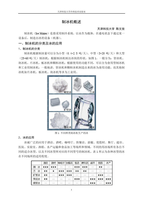
一、制冰机的分类及冰的应用1、制冰机的分类制冰机根据制冰量可以分为小型(0.4-2.5吨/天)、中型(3-20吨/天)和大型(25-60吨/天)制冰机;根据制冰机制出冰块的形状,如图1,一般分为:管冰机、块冰机、片冰机、板冰机和颗粒冰机;根据使用的功能不同,可以分为食用型制冰机和工业用制冰机;一般地讲,管冰机和颗粒冰机制造出来的冰为食用功能,而其他制冰机如片冰机、板冰机、块冰机等多为工业用。
图1 不同种类制冰机生产的冰2、冰的应用冰被广泛的应用于酒店、酒吧、咖啡厅、快餐店、游艇、度假村、舞厅、超市、医院、实验室、渔船、水产运输和食品加工等场所和领域,不同的用冰场所有各自不同的适合冰型,以及不同冰型所对应的不同型号的制冰机。
表1所示为各种冰型的冰在不同场所的适用程度。
二、制冰机冷凝方式的分类1、风冷冷凝器冷却性能由环境温度来决定,环境温度越高,冷凝温度也越高。
一般地,采用风冷冷凝器,冷凝温度比环境温度高 7~12℃,这个值我们称为换热温差。
冷凝温度越高,制冷机组的制冷效率就会越低,所以我们就要控制这个换热温差不应太大。
但是如果换热温差变小,那么风冷冷凝器的换热面积及循环的风量就要增大,风冷冷凝器的造价成本就越高。
温度极限不高于55℃,不低于20℃。
通常情况下,环境温度超过32℃的地区都不建议采用风冷冷凝器。
所以是否可选择风冷冷凝器,首先要确认环境温度。
一般设计风冷制冰机时,必须要求客户提供当地全年最高的环境干球温度。
优点:1、无需水资源,运行成本较低;2、安装、使用方便,无需其他配套设备,只要接通电源即可投入运行;3、不污染环境;4、适用于严重缺水或供水难得地区。
缺点:1、成本投入较高;2、冷凝温度较高,使制冷机组的运行效率降低;3、不适用于空气污浊、有沙尘气候的地区。
英国兰德EcoWise系列水冷冷藏器产品介绍说明书

The Agility water-cooled chillers with R-513A are part of the Ingersoll Rand EcoWise portfolio of products designed to lower environmental impact by using next-generation, low global warmingpotential (GWP) refrigerants without compromising performance and reliability.Agility water-cooled chillersCompact chillers that fit your needs Simplex Chiller Model HDWA175 to 425 ton – 60 Hz, 50 Hz using either R-513A or R-134aCompactThe addition of the Agility™ chiller to the Trane portfolio provides the next step in compact chillers. Providing best-in-class size, the Agility chiller portfolio provides an optimized footprint that minimizes installation costs making it the best choice for existing building applications. The Agility chiller fits through a standard double door (72 inch x 80 inch) fully assembled, and can be easily separated into two sections that fit through a single door (36 inch x 80 inch).EconomicalThe Agility chiller delivers the best balance of size and efficiency, all while helping to keep installation costs low. Leveraging oil-free, magnetic bearings with optimized compressor speeds and the latest Trane proprietary (CHIL™) heat exchanger designs, thesetechnologies enable a smaller footprint while delivering Integrated Part Load Values (IPLV) over 40 percent better than the ASHRAE® 90.1-2016 plus high full-load values. The Agility chiller’s compact size will keepinstallation costs low, and its efficiency will help reduce electrical consumption (kWh or part load) as well as demand charges (kWh or high load) contributing to low operating expenses.ReliableThe Agility chiller has legendary Trane reliability designed in from the start. It utilizes a two-stage, semi-hermetic centrifugal compressor with apermanent magnet, refrigerant-cooled motor delivering efficient, stable operation across a wide operatingmap. Couple this with Trane AdaptiView™ unit controls and customers will enjoy maximum flexibility to meet their applications’ needs. Trane controls also allow for remote connectivity, enabling optimum unit performance to deliver reliable and efficient operation. All of this is backed by factory available extendedwarranties with coverage up to and including 10 years for parts, labor and refrigerant — truly covering the whole chiller.Next-Generation RefrigerantThe Agility chiller’s design is optimized with the next-generation, low-GWP refrigerant R-513A in mind. This refrigerant provides a 55 percent drop in GWP over R-134a helping customers meet sustainability goals by reducing the impact to the environment. The Agility chiller can also be selected with R-134a refrigerant.Trane – by Trane Technologies (NYSE: TT), a global climate innovator – creates comfortable, energy efficient indoor environments through a broad portfolio of heating, ventilating and air conditioning systems and controls, services, parts and supply. For more information, please visit or .© 2020 Trane. All Rights Reserved.All trademarks referenced in this document are the trademarks of their respective owners.HWDA-SLB002-EN05/14/2020Unit ConfigurationCompressorShell Config (EVAP/COND)200020/020300020/020300040/040400040/040Base Unit Dimensions (Assembled)Length WidthHeightin mm in mm in mm 129.9330067.4171372.21833129.9330067.4171372.21833129.9330070.7179578.01981129.9330070.7179578.01981Unit ConfigurationCompressorShell Config (EVAP/COND)200020/020300020/020300040/040400040/040Space EnvelopeLength (E L )Width (E W )Height (E H )in mm in mm in mm 300.87641139.43553108.22753300.87641139.43553108.22753300.87641142.73635114.02901300.87641142.73635114.02901Unit ClearanceTube Pull (C L 1)Non-Tube Pull (C L 2)Height (H C )in mm in mm in mm 129.9330041.0104136.0920129.9330041.0104136.0920129.9330041.0104136.0920129.9330041.0104136.0920Cont/Cond SectionWidth (W 1)Height (H 1)in mm in mm 33.885872.2183333.885872.2183333.885978.0198133.885978.01981Comp/Evap SectionWidth (W 2)Height (H 2)in mm in mm 34.988663.4161035.289368.4173835.289368.4173835.289368.41738Unit Voltages• 460/480V 60 Hz• 575/600V 60 Hz • 208/230V 60 HzComp/EvapSectionCont/CondSectionBase Unit(Assembled)Space EnvelopeE WC L 1/ C L 2C L 1/ C L 236" (920 mm)36" (920 mm)WidthLengthE LLengthHeightWidth H 1W 1H 2W 2Dimensions do not include waterboxes, hinges or other unit-mounted options that may affect unit size. 1. CL1 can be at either end of the machine and is required for tube pull clearance.2. CL2 is always at the opposite end of the machine from CL1 and is required for service clearance.Contact your Trane representative for more information.。
IM-220AA IM-220AWA L1M028306 (022022)商用组合式方冰制冰机使用说

中文
注意
拆除运输包装纸箱、胶带和其它包装材料。 如果内部遗留包装材料,制冰机将无法正常工作。
注:
本制冰机需使用储冰箱。 星崎推荐使用下列储冰箱: B301SA-------------IM-220AA B501SA (带顶部套件8D)--IM-220AA B801SA (带顶部套件4DM) IM-220AA x 2
5) 撕掉外表面的塑料防护膜。 如果制冰机暴露于阳光下或热源下,请待制冰机冷却后再撕掉塑料防护膜。
a) 前盖板 :
b) 顶面板 :
c) 后面板 : d) 侧面板 :
拆下螺钉。 将前面板 上提并向外拉动。 提起前面板,并滑入后 侧以松开后部的挂钩。 拆下螺钉,取下后面板。 拆下螺钉,取下侧面板。
储冰控制 开关
将冰槽置于制冰机边框中,然后将排水盘装回原位。 9) 将制冰机面板装回原位。
4
安装托架
制冰机
带垫 密封圈 排水盘
中文
冰槽 制冰机边框
六角头螺栓 垫圈(附件)
尼龙索
安装边框 储冰控制开关
6. 电气连接
警告
本制冰机必须接地 本制冰机必须按所在国家和地区的电气安全标准进行接地。
监督和指导。 * 另外还应对幼童加以看管,以确保其不玩耍本产品。 * 请勿尝试改装制冰机。 应仅由具备相应知识的作业人员实施拆解或维修作业。
1
中文
I. 安装说明 1. 构造
顶板 前盖板 储冰箱门
把手 储冰箱
电源线 通风窗、空气过滤网
可调节支脚
2. 附件
使用说明书
1
进水软管
1
排水软管
1
安装托架
2
带垫圈六角头螺栓
* 通常情况下,应由持有电工资质证书或经授权的维修人员进行作业。
MODELHOSHIZAKI 冰箱冰罐机说明书
MODELHOSHIZAKICUBELET ICE DISPENSER(FINAL) PARTS LISTDCM-240BAFG-0June 1997H-0Dec., 1997J-0Jan., 1999K-0Dec., 1999L-0Jan., 2001AUG. 26, 2002REVISED:ISSUED:AUG. 6, 1999NO.71147MATERIAL ABBREVIATIONSALUMINUM= Aluminum= CopperPLASTICABS=Acrylonitrile -butadiene - styreneAC=PolyacetalEV A=Ethylene vinyl acetateP A=Polyamide = NylonPC=PolycarbonatePE=PolyethylenePES=PolyesterPETP=Polyethylene terephthalate = TetlonPP=PolypropylenePS=PolystyrenePIFE=Polytetrafluoroethylene = TeflonPUR=PolyurethanePVC=Polyvinyl chlorideRUBBERVN=Vinyl NitrileEPDM=EP rubberNBR=Nitrile butadiene rubberNR=Natural rubberNP=NeopreneSI.R=Silicone rubberSY.R=Synthetic rubberEPH=EpichlorohydrinSTEELGS=Galvanized steelSS=Stainless steelPS=Plated steelP AS=Primed steelAUXILIARY CODEEx.1K-0Parts are the same as in the preceding(Note) - = Part deleted.year.x = Part deleted and replaced"K" is the tenth in alphabetical order with "I" by "o" part.skipped. So, "K" indicates "2000".o = New part for "x"Ex.2L-0 in the same auxiliary code."L" is the next in alphabeticalorder. So, "L" indicates "2001".Ex.3L-1Each time a part is changed non-interchangeably,in a year, this number advances.2DCM-240BAF A. ICE DISPENSER ASSEMBLYG-0, H-0, J-0, K-0, L-03DESCRIPTION MATERIALOR MODELPARTNUMBERREQUIRED NUMBERNUMBERG-0H-0J-0K-0L-0 B FRAMEASSEMBLY - 1A0174A01 1 1 1 1 1 ICE MAKING UNITASSEMBLY- 220559A03 1 1 1 1 1 SOCKET HEAD HEX BOLT SS, 8 x 90 7S12-0890 3 3 3 3 3SPRING WASHER SS, 8 3 3 3 3 3D REFRIGERATIONCIRCUIT - 2A0783A01 1 1 1 1 1 WATER CIRCUIT ASSEMBLY - 2A0778A01 1 1 1 1 1 CONTROL BOX (A) - 2A0788A01 1 1 1 1 14DESCRIPTION MATERIALOR MODELPARTNUMBERREQUIRED NUMBERNUMBERG-0 H-0 J-0 K-0 L-0 TOPSUPPORT 2A0767-01 1 1 1 1 1 TRUSS HEAD SCREW 4 x 8 7C31-0408 4 4 4 4 4 COLLAR 4H0171-01 5 5 5 6 6 FLAT HEAD SCREW SS, 4 x 12 7C22-0412 5 5 5 6 6 FLAT WASHER SS, 4 7W22-0400 5 5 5 6 6 TRUSS HEAD SCREW 4 x 8 7C31-0408 1 1 1 1 1 THUMBSCREW - 415949G08 1 1 1 1 1 FRONT BARRIER (L) 425094-01 1 1 1 1 156DCM-240BAFB. FRAME ASSEMBLYG-0, H-0, J-0, K-0, L-0MODEL: DCM-240BAF TITLE: B. FRAME ASSEMBLYDESCRIPTION MATERIALOR MODELPARTNUMBERREQUIRED NUMBERNUMBERG-0 H-0 J-0 K-0 L-0 RIGHT SUPPORT ASSEMBLY 2A0760G01 1 1 1 1 1FT SCREW SS, 4 x 8 7F32-0408 4 4 4 4 4LEFT SUPPORT ASSEMBLY 2A0759G01 1 1 1 1 1FT SCREW SS, 4 x 8 7F32-0408 4 4 4 4 43 COMPRESSORSUPPORT 2A0755G01 1 1 1 1 1 TRUSS HEAD SCREW 4 x 8 7C31-0408 4 4 4 4 4LOCK WASHER SS, 5 7L22-0500 4 4 4 4 4NUT SS,5 4 4 4 4 478DCM-240BAFC. ICE MAKING UNIT ASSEMBLYG-0, H-0, J-0, K-0, L-0M ODEL: D CM-240BAF TITLE: C. IC E M AK ING U NIT ASSEM BLYDESCRIPTIO N M ATERIALOR M ODELPARTNUM BERREQUIRED NUM BERNUM BERG-0H-0J-0K-0L-0 SHUTTERASSEM BLY 211265A09 1 1 1 1 1 VER ASSEM BLY - BIN 207757A01 1 1 1 1 1 EAR M O TO R TC1185 1 Ø120V 80W2U0147-01 1 1 1 1 1 UPLING-SPLINE 418316-01 1 1 1 1 1 USING206013G03 1 1 1 1 1910DCM-240BAFD. REFRIGERATION CIRCUITG-0, H-0, J-0, K-0, L-0MODEL: DCM-240BAF TITLE: D. REFRIGERATION CIRCUITDESCRIPTION MATERIALOR MODELPARTNUMBERREQUIRED NUMBERNUMBERG-0H-0J-0K-0L-0 1 COMPRESSOR J525-CIE 4A1177-01 1 1 1 1 1GROMMET 434403-01 4 4 4 4 4 3 SPACER 434404-01 4 4 4 4 4BOLT 437889-01 4 4 4 4 4 CONDENSER 2A0780-01 1 1 1 1 1 FT SCREW SS, 4 x 8 7F32-0408 2 2 2 2 2FANSHROUD 3A0715-01 1 1 1 1 1 T2SCREW 4X8 7P31-0408 6 6 6 6 6DCM-240BAF E. WATER CIRCUIT G-0, H-0, J-0, K-0, L-0MODEL: DCM-240BAF TITLE: E. WATER CIRCUIT ASSEMBLYDESCRIPTION MATERIALOR MODELPARTNUMBERREQUIRED NUMBERNUMBERG-0H-0J-0K-0L-0 WATERPIPE 2A0787G01 1 1 1 1 1 2 WATERVALVE S-30 4A0865-01 2 2 2 2 2 TRUSS HEAD SCREW SS, 4 X 8 7C32-0408 2 2 2 2 23 WATERVALVE - 4A2077-01 1 1 1 1 1 TRUSS HEAD SCREW SS, 4 X 8 7C32-0408 2 2 2 2 2WASHER K-59963 4A0867-01 2 2 2 2 2 VINYLHOSE L=65 7716-0913 1 1 1 1 1 SILICONEHOSE L=300 7725-0912 1 1 1 1 1DCM-240BAF F. CONTROL BOX (A) ASSEMBLY G-0, H-0, J-0, K-0, L-0MODEL: DCM-240BAF TITLE: F. CONTROL BOX (A) ASSEMBLYDESCRIPTION MATERIALOR MODELPARTNUMBERREQUIRED NUMBERNUMBERG-0H-0J-0K-0L-0 CONTROLBOX(A) 2A0769-01 1 1 1 1 1CONTROLBOXCOVER 3A0714-01 1 1 1 1 1 TRUSS HEAD SCREW 4 X 8 7C31-0408 2 2 2 2 2RELAY LY2F24V 406132-03 3 3 3 3 3 RELAY LY1F120V418271-03 1 1 1 1 1 TAPPINGSCREW 431415-01 8 8 8 8 8 6 TRANSFORMER BE141625GEK4A0557-01 1 1 1 1 1DCM-240BAF G. CONTROL BOX (B) ASSEMBLY G-0, H-0, J-0, K-0, L-0MODEL: DCM-240BAF TITLE: G. CONTROL BOX (B) ASSEMBLYDESCRIPTION MATERIALOR MODELPARTNUMBERREQUIRED NUMBERNUMBERG-0H-0J-0K-0L-0 CONTROLBOX(B) 2A0771-01 1 1 1 1 12 STARTCAPACITOR 145-174µf250VAC3A0076-11 1 1 1 1 1 3 CAPACITOR 10µf 280V 416921-05 1 1 1 1 1T2 SCREW 4 X 8 7P31-0408 1 1 1 1 1PLUGHOUSING 3191-06P 412832-03 1 1 1 1 1 STRAP 434580-13 1 1 1 1 1 T2 SCREW 4 X 8 7P31-0408 1 1 1 1 1DCM-240BAF H. MIDDLE FRONT PANEL ASSEMBLY G-0, H-0, J-0, K-0, L-0MODEL: DCM-240BAF TITLE: H. MIDDLE FRONT PANEL ASSEMBLYDESCRIPTION MATERIALOR MODELPARTNUMBERREQUIRED NUMBERNUMBERG-0 H00056M-H01105K H01106L-H01205LJ-0 K-0 L-0MIDDLE FRONT PANEL -PAINTED3A0796G01 1 1 -3A0796G02 1 1 1 1 PUSHSWITCH 2AP-1B 435745-02 1 1 1 1 1 1 SWITCHBRACK ET 4A1207-01 1 1 1 1 1 1 TRUSS HEAD SCREW SS, 4 X 8 7C32-0408 3 3 3 3 3 3 ERSWITCH HLS112D 421491-08 1 1 1 1 1 1DCM-240BAF K. LABEL LOCATION G-0, H-0, J-0, K-0, L-0MODEL: DCM-240BAF TITLE: K. LABEL LOCATIONDESCRIPTION MATERIALOR MODELPARTNUMBERREQUIRED NUMBERNUMBERG-0H-0J-0K-0L-0 INSTRUCTIONSHEET 2A0849-01 1 1 1 1 1 2 INSTRUCTIONLABEL 2A0847-01 1 1 1 1 1 MODEL NUMBER LABEL 4A0468-27 1 1 1 1 1 LABEL - PENGUIN 4A0526-02 1 1 1 1 1 NAMEPLATE 4A1192-01 1 1 1 1 1 LABEL - AIR FILTER 426177-01 1 1 1 1 1 LABEL - CLEANING 2A0848-01 1 1 1 1 1 8 WIRINGLABEL 3A0784-01 1 1 1 1 1DCM-240BAF L. SHUTTER ASSEMBLY G-0, H-0, J-0, K-0, L-0MODEL: DCM-240BAF TITLE: L. SHUTTER ASSEMBLYDESCRIPTION MATERIALOR MODELPARTNUMBERREQUIRED NUMBERNUMBERG-0H-0J-0K-0L-0 ET-SOLENOID 320896G02 1 1 1 1 1 2 SPACER ABS(GRAY) 432514-01 1 1 1 1 1 SCREW SS, 4 X 12 434838-02 4 4 4 4 4SOLENOID AS-20-No.75437926-01 1 1 1 1 1 TRUSS HEAD SCREW SS, 4 X 10 7C32-0410 1 1 1 1 1TOOTHWASHER M4 7R21-0400 1 1 1 1 1 SCREW SS, 4 X 8 434838-01 1 1 1 1 1SHAFT 441645G01 1 1 1 1 1DCM-240BAF M. COVER ASSEMBLY BIN TOP G-0, H-0, J-0, K-0, L-0MODEL: DCM-240BAF TITLE: M. COVER ASSEMBLY - BIN TOPDESCRIPTION MATERIALOR MODELPARTNUMBERREQUIRED NUMBERNUMBERG-0 H-0 J-0 K-0 L-0 COVER-BINTOP 103829G01 1 1 1 1 1 SHAFT 423958-01 1 1 1 1 1 BALANCEPLATE 423959-01 1 1 1 1 1 SNAPPIN SS,SSP-4 715S-0004 1 1 1 1 1 "E"RING SS,5 721S-0005 1 1 1 1 1 BALANCEPLATE 417473-02 1 1 1 1 1 MICROSWITCH V-5L11155W423950-01 1 1 1 1 1 PAN HEAD SCREW SS, 3 X 16 7C12-0316 2 2 2 2 2DCM-240BAF N. ACCESSORIES G-0, H-0, J-0, K-0, L-012MODEL: DCM-240BAF TITLE: N. ACCESSORIESDESCRIPTION MATERIALOR MODELPARTNUMBERREQUIRED NUMBERNUMBERG-0H-0J-0K-0L-0 INSTRUCTIONMANUAL PAPER 91A2AA10A 1 1 1 1 1 FUSE 4A0893-01 1 1 1 1 1。
泰勒公司C712 C713型冰淇淋冷冻机缩写服务手册说明书
C712/C713 型
冰淇淋冷冻机 缩写服务手册
服务手册
062179CS
2005ቤተ መጻሕፍቲ ባይዱ5月20日
斯科茨曼MF22,30,41,51,61制冰机

制冰机 ............................................................................................................ 41
水系统清洁和消毒说明 .......................................................................................... 41
概述和安装............................................................................................................ 12 A. 介绍 ............................................................................................................ 12 B. 拆箱和检查 ..................................................................................................... 12 C. 选择安装位置和调整水平 ................................................................................ 13 D. 电源连接 ......................................................................................................... 14 E. 进水和排水连接 .............................................................................................. 14 F. 安装检查单 ..................................................................................................... 14 G. 安装实例 ......................................................................................................... 15
亚特兰蒂斯科 Atlas Copco TCA 55-215型号混合工业冷却机说明书
Hybrid Industrial Cooling Chiller TCA 55-215IntroductionTCA 55-215Hybrid Industrial Cooling ChillerTCA- USAAtlas Copco TCA55-215 series is a hybrid plug’n’play water chiller. It's specificities include a free-cooling section and adiabatic pre-cooling (patented adiabatic system) on inlet. The cooling capacity ranges from 55 to 228 kW.Reliable and robust, equipped with proved scrollcompressors, air-cooled microchannel condensers and integrated hydro module, it provides easy and cost-effective installation and maintenance and safety for your day-to-day operations.Atlas Copco TCA55-215A's range fully complies with the Eco Design Directive 2021 meeting the Seasonal Energy Performance Ratio (SEPR1) to reach the highest level of energy saving.Using energy-efficient equipment made by Atlas Copco,you reduce production costs and increase the competitiveness of your company.The components of the chiller allow it to be used in a wide range of applications and across industrial sectors.The use of a shell’n’tube evaporator enables to achieve the highest level of reliability with various types ofprocesses in both closed and open hydraulic circuits. All configurations can have a built-in hydro circuit with buffer atmospheric tank and single or double (work/stand-by)pumps with a wide range of working pressures (1, 3, 5bar). The list of applicable segments includes, but is not limited to, mechanical engineering, all types ofmetalworking, food and beverages, pharmaceuticals,cement industry, chemistry and petrochemistry, oil and gas industry, cooling of data centers andtelecommunication hubs, plastic production of all types.TCA55-215 series chillers can be installed both indoors and outdoors, thanks to the use of the necessary reliable components with IP54 protection. This enables to save internal space, optimize the distribution of cooling water and allows the chiller to work with air temperature. It is especially efficient during winter to make use of the cold air to gain efficiency with free-cooling coils.Plug’n’play solution for process cooling systemsMaximum energy efficiencyVariety of industrial applicationsFor indoor and outdoor installationIndustry-standard level of efficiency and lower cost withphase-cut regulation (std for TCA-A)Premium efficiency level with EC brushless fans to ideally meet partial loads for your industrial application. Standard for TCA-AF, -AD, -P versions and optional for TCA-A version.Proven algorithms provide operational efficiency for the whole range.You can always track the machine status and working parameters using Atlas Copco Smartlink connection. Built-in set of safety options like phase sequence relay provides ultimate protection and reduced risk of malfunction.Speed-Regulated Axial Fans Elektronikon MarkV Touch withSmartlinkTCA- USAImmune to galvanic corrosion.Light-weighted with a high rate of heat transfer. Provides lower cost of maintenance with reduced refrigerant charge.Saves up to 40% of the chillers energy compared to non-free cooling units.Integrated solution for easy installation and smaller footprint.Optimal balance between clogging-free water flow, heat transfer and life-cycle cost with this tube-fin free-cooling heat exchanger.Total free-cooling starting from deltaT of 5,5 degrees with the set-point of 15 degrees.Closed atmospheric for a wide range of applications. Protected continuous operation with a set of onboard safety devices.Twin refrigerant circuit for redundancy.Electronic expansion valve (EEV) as standard option for highest energy efficiency, flexibility and time saving during maintenance.Continuous uptime and perfect serviceability with the industry-standard scroll compressor.Option of low-noise jacket for sensitive applications.Vast range of configurations with maximum available pressures of 1, 3 or 5 bar to meet the variety of hydro circuitsStand-by pump with automatic switching available in all versions for operation with no interruptionImpellers made in 316L stainless steelIE3 efficiency motorPatented evaporative cooling system provides peak temperature safety during operation.Cooling capacity boost up to 17% for dry climatic conditions.Durable components in stainless-steel.Strainer and water hammer arrestor on inlet as standard. Easy installation with one point of connection.Vaste range of connections to meet your needs: BSP and NPT tread, UNI or ASME flanges.Easy and fast connection for manual or automatic cooling circuit filling and adiabatic system with 1/2 inch female tread.Manual (std) evaporator bypass to prevent chiller from interrupted process water circulation.Can withstand long-term temperature loadsIdeal balance between oil return, heat transfer rate and energy efficiency with two-pass heat exchanger for your cooling process.Robust and reliable for any type of industrial application. Well-suitable for open circuit.Microchannel Condensers with Epoxy CoatingFree-Cooling CoilsInsulated On-board Water Tank Refrigerant circuit with Hermetic Scroll Compressors Pumps with stainless-steel impeller Adiabatic System PadsHydro ConnectionsShell-n-Tube Evaporator5TCA- USAWhen operating in ambient temperatures higher than the set-point, the TCA55-215 chiller works as an ordinary chiller. The hot inlet water flow goes through the motorized valve directly to the evaporator.After passing the evaporator, the water flow goes into a water tank containing a set of safety sensors. It then flows to a pump group, which consists of one or two pumps with outlet pressure versions of 1, 3 or 5 bar bringing cooled water to the application.An external temperature sensors, allows the switch to free-cooling. When the ambient air temperature drops to a lower temperature, the motorized valve allows the inlet water flow water to run through the free cooling system. Lower ambient air temperature is more energy efficient to cool the water in the system by running it through the tube-fin heat exchanger.When the ambient temperature, goes even lower, the motorized valve continues to lead the whole inlet flow to the free-cooling heat exchanger, the heat-transfer then goes in a total free-cooling mode.When the chiller operates using only the mechanical energy of the compressors, the water goes through the motorized valve directly to the evaporator where its temperature is lowered to the desired set-point thanks to the work of the refrigerant circuit.When the ambient temperature comes closer to the set-point, the chiller starts to work in a partial free-cooling mode. The refrigerant circuit operates with a lowered load based on the water temperature in the tank, to prevent negative impact on the outlet water temperature.In total free-cooling mode, a built-in free cooling module allows the TCA55-215AF, -AP to take advantage of the low outdoor air temperatures in the water-cooling process. During free-cooling, the compressors are fully at stop, which is highly energy efficient and significantly increases the life of the compressor.The air inlet is situated on the surface's side of the chiller going through the free-cooling coils and the microchannel condensers. On top of the machine are two speed-regulated axial fans that create an air flow which fully reveal their efficiency, especially during partial loads.In free-cooling mode the ambient temperature alone is sufficient to decrease the water temperature to the desired set-point. In this case the speed-regulated axial fans are the only consumer of electrical energy.Our standard air-cooled chiller has a reduced performance when the ambient temperature rises. Therefore, a chiller must be sized using peak temperatures for the region where it should be installed. A maximum cooling capacity specific for the application should also be taken as an input for calculations.This can lead to higher initial costs as well as more energy consumption and a larger footprint. However, 90% of the time the ambient temperature will be lower than a peak temperature.Our TCA-AD and TCA-AP variants offer a solution which allows to decrease inlet cooling air temperature moisturizing it with adiabatic panels situated on both sides of the chiller.Only when needed, tap water goes into the adiabatic system through an inlet placed on the back side of a chiller together with other water connections and then it is injected on the adiabatic pads.The adiabatic function operates under control of our Elektronikon Mk5S Touch using a patented water consumption control system and control philosophy with the aim to reduce tap water consumption as much as possible without losing the set-point control.1.Water flow2.Refrigerant flow3.Air flow4.Adiabatic7TCA - ARobust industrial chillerSaves up to 40% of the chillers energy.TCA - AFIndustrial Chiller with Integrated Free-Cooling Peak temperature safety and cooling capacity boost up to 17% in dry climate conditions.TCA - ADIndustrial Chiller with Adiabatic Pre-CoolingTCA- USAThe TCA chiller is applicable for a variety of applications such as the cooling of a photovoltaic power station or a plastic machine, for a telecommunication rig and a chemical bath. This chiller range show exceptional robustness and efficiency. The free-cooling chiller fully reveals its effectiveness when the outlet water temperature set-point higher than 12°С, resulting in energy savings up to 40% of the total consumption.Wide range of applicationsThis graph shows the difference between the energy consumption of a free-cooling chiller versus non-free-cooling variant. When the TCA is operating in free-cooling mode, only the speed-regulated fans are consuming energy and compressors, the main energy consumer for a chiller are either off or working in a partial load mode. The graph’s blue zone shows the direct benefit form using the free-cooling principle.A = Kw/hB = Degrees F 1 = Chiller2 = Free-cooling3 = Free-cooling savings zoneTotal power consumption vs. Temperatureduring the year9Free-cooling savingsAtlas Copco’s engineering team has many years of experience indesigning and calculating complex energy saving equipment.Based on estimations and prepared for different climatic zones, wecan state with confidence that the benefits from using an integratedfree-cooling TCA55-215 chiller can bring you up to 40% savings oftotal power consumption for a 5 year life-cycle cost.A = ElectricityB = Purchase costC = 39% Free cooling savingsTCA- USAFeatures table TCA 55-215GeneralF-gas R407C GWP1774 IP grade IP54Installation Lifting with bars + ropes + sprader beam Standard Forklift Standard (only for TCA 55-65)Electrical400V/3ph 50Hz IEC Standard 460V/3ph 60Hz IEC (with electrical components UL marked)Standard 400V/3ph 60Hz UL 508A StandardControlController type Elektronikon MKVS 4,3 inch touch screen Standard Text on display in local language Standard Day and week scheduler Standard Service timer Standard Refrigerant High pressure transmitter (digital)Standard Refrigerant Low pressure transmitter (digital)Standard Automatic priority for compressors Standard Compressor direct on line starter (DOL)StandardSafetyPhase sequence motor direction Standard Thermal-magnetic circuit breakers protection on compressors, pump and fan Standard High pressure switch with manual reset Standard Flow switch - paddle type Standard Low pressure switch - with auto reset (with hysteresis)StandardLow pressure transmitter - with auto reset (hysteresis)Standard Winter protection: auto-on of the pump with low ambient temperature (softwarefunction)Standard Anti flood system (if automatic filling system included)StandardExpansion valve Electronic expansion valve (EEV)StandardCompressorScroll Standard Crankcase heater Standard Noise reduction jacket StandardSystem integrationRemote on/off StandardSingle free contact for all alarms StandardRemote setpoint + temperature transmission (4.20mA)OptionalModbus RTU - RS480AccessoryProfibus AccessoryProfinet Accessory11Features table TCA 55-215System integrationTCP Accessory Ethernet IP Accessory CANbus Accessory Remote control panel AccessoryConnectivity Smartlink connectivity includes modem (3D) and service license Standard Smartlink UPTIME license optionalFreecooling Aluminum fins copper tube cooling coil n/a Standard Three way valve (free cooling control)n/a StandardAdiabatic systemAdiabatic pads, controlled by patented philosophy n/a Standard n/a Standard Descaling inline filters for adiabatic water system (delivered loose)n/a Optional n/a OptionalHydronicsNo pump StandardPump 1P non-ferrousPump 3P non-ferrousPump 5P non-ferrousPump 1P non-ferrous + standby unitPump 3P non-ferrous + standby unitPump 5P non-ferrous + standby unitNo tank Standard Internal epoxy coated tank, externally painted and insulated, closed circuit Standard Hydro devices included: solenoid valve, water level sensor, city water line filter, safety relief valve(2,5 bar), venting valve, drainStandardManual filling systemAutomatic filling system (solenoid valve, tap water filter, MKVS controlled)External manual by-passWater pressure gauge (only if pump is included)Groover water connectionsFlanges EN 1092-1 type 13B/PN16 galvanized carbon steel (ex UNI 2254-67)Optional Flanges ASME/PN16 Galvanized carbon steel OptionalCounterflanges Optional Gas male threaded water connections = BSP (British Standard Pipe)OptionalNPT (only for TCA 55-65)Optional Water strainer (delivered loose, brass, 500 micron)OptionalFanAC variable speed fan (phase circuit controlled above 14°F)Standard n/a EC variable speed fan (brushless fan with integrated control, sutiable above -4°F ambient)Optional StandardCondenserCondenser (Microchannel) - with epoxy powder coating StandardCleanable condenser air filter (frame and mesh in aluminum)Standard Optional Standard OptionalEvaporator Shell and tubes heat exchanger StandardRefrigerant circuitSight glass Standard Liquid receiver Standard Filter dryer StandardPackaging Pallet and plastic wrap protection StandardWooden crate OptionalSea-worthy wooden box Optional TCA- USATCA ACooling capacity (1) BTU/Hr189,714.98215,647.25258,298333,366.08406,044.66518,645.28638,070.18706,312.98 Total absorbed power (1) kW19.524.226.234.645.753.075.186.8EER (1) 2.85 2.61 2.89 2.82 2.60 2.87 2.49 2.38 Cooling capacity (2) BTU/Hr256,251.71326,541.8368,169.91463,027.4585,182.01757,495.08911,041.381,016,817.72 Total absorbed power (2) kW18.523.425.431.441.950.872.383.9EER (2) 4.06 4.09 4.25 4.31 4.09 4.37 3.69 3.55 TCA AFCooling capacity (1) BTU/Hr184,255.56207,799.33246,356.51321,082.37402,291.31511,479.79615,891.27698,806.28 Total absorbed power (1) kW20.124.427.336.648.654.476.487.4EER (1) 2.68 2.50 2.64 2.57 2.42 2.75 2.36 2.34 Cooling capacity (2) BTU/Hr252,498.36319,376.3363,734.12451,084.91576,310.45742,481.66896,027.961,001,121.88 Total absorbed power (2) kW18.523.625.031.142.051.170.685.1EER (2) 4.01 3.97 4.27 5.25 4.02 4.25 3.72 3.45Total Free cooling at (4) (°F)49.146.449.146.442.844.64137.4Total absorbed power (4) kW 6.6 6.69.99.99.99.99.99.9EER (4)11.214.210.813.417.122.026.529.6 TCA ADCooling capacity (1) BTU/Hr196,198.05229,295.81282,525.19369,875.98458,250.40568,803.74692,835.03778,991.56 Total absorbed power (1) kW17.422.723.531.639.645.764.473.6EER (1) 3.30 2.96 3.53 3.43 3.39 3.65 3.16 3.11 Cooling capacity (2) BTU/Hr268,194.20332,683.65402,973.73504,314.29637,046.54791,616.48939,362.141,135,901.41 Total absorbed power (2) kW16.222.222.428.938.542.963.977.2EER (2) 4.84 4.40 5.28 5.12 4.85 5.41 4.31 4.1913TCA APCooling capacity (1) BTU/Hr194,423.74225,951.91268,774.27347,935.92426,688.11553,176.14684,099.95771,655.46 Total absorbed power (1) kW17.8823.1323.6030.8538.9047.4266.1576.31 EER (1) 3.19 2.86 3.34 3.30 3.22 3.42 3.03 2.96 Cooling capacity (2) BTU/Hr265,805.71333,366.08379,771.18477,358.39604,631.21775,579.42938,338.51,089,156 Total absorbed power (2) kW16.622.522.428.438.044.465.479.9 EER (2) 4.70 4.34 4.97 4.93 4.66 5.12 4.21 4.00TCA- USANotes15Atlas Copco Compressors300 Technology Center Way, Suite 550 Rock Hill, SC 29730Phone: 866.546.3588 2 9 3 5 0 7 7 4 0 0。
海士卡基立方冰块机零配件清单说明书
No.4253 No.248
CONT Plug UK & MIDDLE EAST OCEANIA CHINA
DCM-120KE-P DCM-120KE-P
FT10416F0 FT20416F0 FST0508F0 P02552-01 263224M01 264001M01 376454M01 377811M01 376455M01 420470-06 427902-05 427902-04 FSK0408S0 259891P01 P02697-01 P02698-01 P02760-01 P00193-01 448949-01 121899M01 121900M01 121901M01 FSG0408S0 121228P01 341489G01 376725M01 121230P02 379018M01
50Hz 50Hz / 60Hz
50Hz 50Hz 50Hz 50Hz 50Hz 50Hz / 60Hz 50Hz 50Hz
Auxiliary Codes
Auxiliary Code Breakdown
The auxiliary code is the first two characters in the serial number. The first character indicates the year. Years progress or regress in alphabetical order. The series runs from "A" through "V" and the letters "I" and "O" are skipped. The second character indicates significant part changes within a year. Base is "0" and this number advances for each change. In cases where there is a letter in parentheses, this designates the month. This is the last character in the serial number. The series runs from "(A)" through "(M)" and the letter "(I)" is skipped. This designation is only included when identifying a parts change within an auxiliary code.
斯科茨曼Ice1_2_3制冰机
第4页
规格
外型尺寸:
高 宽 深 重
718 mm 457 mm 478 mm 39 公斤
冰-1 制冰机 规格
型号 冰-1
冷却方式 风冷
外表材质 不锈钢
压缩机功率 (马力)
1/4
储冰槽容量 14 公斤
每天耗水量 (升/24 小时)
110 290*
电源
电流
220V 50Hz 单相
2.2
基于每次 18 块中型冰块的收冰数量
维护保养和清洁说明 概述 ..................................................................................................................................... 21 制冰机 ................................................................................................................................. 21 水系统清洁说明 ................................................................................................................... 21
IMI Cornelius WWC和WCF冰淇淋机(500系列)说明书
8 638036373-001 Evap Asy
8
9 638090113
Auger
7
10 638090117
Head Extruder Asy WCC
6
638090118
Head Extruder Asy WCF
11
5
11 638090126
Valve Expansion
4
1
12 638036218
MODEL NO.
569200039 569200040 569200041 569200042 569200056 569200057 569200058 569200059 569200060
WWC and WCF ICEMAKER (500 SERIES)
1 of 3
Manual Part No. 638085278IPL500 6-15-2001 Rev; 10-5-01
WCC AND WCF CHUNKLET ICEMAKER (500 SERIES)
19
16
5
4
20
10
18
17
8 1
7 3
9
14
22
2
21
FRONT VIEW
11
6
15
12
RIGHT SIDE VIEW
13
FIGURE 1. REFRIGERATION AND ICEMAKER ASSEMBLY
638010002 5 638004791 6 638036067
638036085 7 638007026-01 8 638007303-04 9 638036168
638036079
- 1、下载文档前请自行甄别文档内容的完整性,平台不提供额外的编辑、内容补充、找答案等附加服务。
- 2、"仅部分预览"的文档,不可在线预览部分如存在完整性等问题,可反馈申请退款(可完整预览的文档不适用该条件!)。
- 3、如文档侵犯您的权益,请联系客服反馈,我们会尽快为您处理(人工客服工作时间:9:00-18:30)。
箱。
1. 为制冰机选择永久的安装位置。 制冰机安装位置的要求包括:
维护保养和清洁说明 概述 ..................................................................................................................................... 21 制冰机 ................................................................................................................................. 21 水系统清洁说明 ................................................................................................................... 21
电线规格 3 X 1.5 mm2
保险丝规格 10A
第9页
概述和安装
序言
本手册提供了冰 1、冰 2 和冰 3 型号制冰机的规格,以及安 装、初次开机、使用、维护保养和清洁的详细步骤。 我们的电脑板控制的制冰和冰块分配器经过严格的设计、工 程测试和制造。 制冰机的制造过程测试严格,能够运用于多种场合,能最大 程度地满足客户的各种需要。 制冰机的工程设计满足我们客户严格的安全标准和性能要 求。
概述和安装 序言 ....................................................................................................................................... 9 拆箱和检查 ............................................................................................................................ 9 选择安装位置和调整水平 ....................................................................................................... 9 电源连接 ................................................................................................................................ 9 进水和排水 .......................................................................................................................... 10 安装检查单 .......................................................................................................................... 10 安装实例 .............................................................................................................................. 11
维修手册
冰1 冰2 冰3
制冷机 包含储冰槽
MS 1000.52 REV. 03/2000
第2页
目录
目录 ................................................................................. 2 规格 冰 1............................................................................. 3 规格 冰 2............................................................................. 5 规格 冰 3............................................................................. 7
操作说明 开机 ..................................................................................................................................... 12 操作检查 .............................................................................................................................. 12
冰-3 制冰机 规格
型号 冰-3
冷却方式 风冷
外表材质 不锈钢
压缩机功率 (马力)
3/8
储冰槽容量 14 公斤
每天耗水量 (升/24 小时)
140 480*
电源
电流
220V 50Hz 单相
3.2
基于每次 24 块中型冰块的收冰数量
*进水温度 15℃。
启动电流 17
功率(瓦) 500
24 小时耗电量 10 kw
调整步骤 调整冰块的大小 ................................................................................................................... 17 调整满冰控制....................................................................................................................... 17 电路图 ................................................................................................................................. 18 维修诊断 .............................................................................................................................. 19
制冰机运行原理 制冰阶段 .............................................................................................................................. 13 收冰阶段 .............................................................................................................................. 13 零部件介绍 .......................................................................................................................... 15
738 mm 457 mm 523 mm 42 公斤
冰-2 制冰机 规格
型号 冰-2
冷却方式 风冷
外表材质 不锈钢
压缩机功率 (马力)
1/4
储冰槽容量 14 公斤
每天耗水量 (升/24 小时)
105 300*
电源
电流
220V 50Hz 单相
2.2
基于每次 24 块中型冰块的收冰数量
*进水温度 15℃。
注意: 为了保证设备的安全和良好的运行状况,按照 本手册的规定进行安装和维护保养是非常重要的。
表面。 9. 检查设备后面铭牌上标注的电源电压是否和当地的电 压相一致。
警告 - 将不正确的电压连接到制冰机上将导致零件索 赔失效。 10. 从客户操作手册中取出工厂的登记卡并填写所有的项 目,包括铭牌上标注的设备型号和序列号。 按照登记卡上的地址将登记卡邮寄给工厂。
水冷式机型
24 小时制冰量 环境温度
24 小时制冰量 环境温度
进水温度
进水温度
注意:冰的日产量直接和进入冷凝器的空气温度和进水温度,记忆设备的新旧程度有关。 为了保持您的制冰机的最高性能表现,参见本手册第21页对制冰机进行定期的维护保养和检查是非常重要的。
第8页
规格
外型尺寸:
高 宽 深 重
790 mm 457 mm 523 mm 44 公斤
选择安装位置和调整水平
拆箱和检查
1. 请通知您当地的经过 SCOTSMAN 授权的经销商或供 应商安装您的制冰机。
危险 – 该制冰机仅供室内安装和使用,如果在超过下 列标注的环境温度范围之外强行使用制冰机将导致 SCOTSMAN 工厂用限的保修失效。
2. 目视检查制冰机的包装箱是否有任何的外观损坏,如 有损坏,应立即将损害情况报告给运输商,并在运输商代表 在场的情况下拆箱检查设备是否有任何潜在的损坏并填写 索赔单。