HEXIN 2108B 转换器说明书
中文智能转换器说明书

MGG/C型电磁流量计使用说明书开封威利仪表有限公司MGG/C型电磁流量计使用说明书1 产品用途与适用范围1.1 特点:■可编程频率低频矩形波励磁,提高了流量测量的稳定性,功率损耗低;■采用16位嵌入式微处理器,运算速度快。
精度高;■全数字量处理,抗干扰能力强,测量可靠,精度高,流量测量范围度可达1500 : 1;■超低EMI开关电源,适用电源电压变化范围大。
抗EMC性能好;■全汉字菜单操作,使用方便,操作简单,易学易懂;■高清晰度背光LCD显示;■具有双向流量测量、双向总量累计功能,电流、频率具备双向输出功能。
■内部具有三个积算器可分别显示正向累计量、反向累计量及差值积算量。
■具有RS485或RS232C数字通讯信号输出;■具有电导率测量功能,可以判别传感器是否空管;■恒流励磁电流范围大,可与不同公司、不同类型的电磁流量传感器配套使用;■具有自检与自诊断功能;■采用SMD器件和表面安装(SMT)技术,电路可靠性高;■仪表内部设计有不掉电时钟,可记录16次掉电时间。
1.2主要用途MGG/C型电磁流量计用来测量封闭管道中导电流体的体积流量。
广泛地适用于石油化工、钢铁冶金、给水排水、水利灌溉、水处理、环保污水总量控制、造纸、医药、食品等工、农业部门的生产工艺过程流量测量和控制;适用于导电液体的总量计量。
1.3正常工作条件环境温度:分体型–10~+ 60℃;相对湿度:5%~90%;供电电源:单相交流电85~265V,45~63Hz;功率:与传感器配套,小于20W。
1.4 试验参比条件环境温度:20℃±2℃相对湿度:45%~85%电源电压:220±2%电源频率:50Hz±5%谐波含量小于5%。
预热时间:30min2产品型式转换器与传感器分离安装的分体型和与传感器组成一体的一体型两种结构形式。
3工作原理电磁流量计的工作原理基于法拉第电磁感应定律。
当一个导体在磁场内运动,在与磁场方向、运动方向相互垂直方向的导体两端,会有感应电动势产生。
GCAN-208CAN光纤转换器用户手册
GCAN-208CAN光纤转换器⽤户⼿册GCAN-208CAN光纤转换器⽤户⼿册⽂档版本:V3.01 (2015/8/4)修订历史⽬录⽬录 (3)1. 功能简介 (4)1.1 功能概述 (4)1.2 性能特点 (4)1.3 典型应⽤ (5)2. 设备安装 (6)2.1 模块固定 (6)2.2 光纤连接 (8)2.3 与CAN总线连接 (8)3. 设备使⽤ (9)3.1 CAN总线配置 (9)3.2 与光纤连接 (10)3.3 与CAN连接 (10)3.4 CAN总线终端电阻 (11)3.5 系统状态指⽰灯 (11)4. 技术规格 (13)5. 常见问题 (14)附录CAN2.0B协议帧格式 (15)1. 功能简介1.1 功能概述沈阳⼴成科技有限公司GCAN-208模块是集成1路标准光纤接⼝(单模、多模,SC、ST可选)、2路标准CAN总线接⼝的⼯业级CAN总线转光纤转换器。
GCAN-208模块可以将CAN总线数据转换成光信号通过光纤传输。
通过成对使⽤GCAN-208模块,⽤户可以轻松的延长CAN总线通信距离、有效的消除长距离通信⼲扰,可以防⽌总线受到电磁⼲扰、地环⼲扰、雷击等对总线和设备造成的损坏。
GCAN-208模块可将CAN总线数据透明、⽆损的转换成光信号,再将光信号透明、⽆损的解析成CAN总线数据。
⼴成科技使⽤独有的总线信号转换技术,可将CAN数据与光信号之间的转换时间做到微秒级,这样就保证了通信的实时性,所以GCAN-208可⽀持任何CAN总线通信协议如:CANopen、SAE J1939、DeviceNet、NMEA2000等等。
GCAN-208模块独特的双通道设备可以同时延长两条CAN总线的通信距离,该模块是⼯业总线改造、长距离通信、隔离总线⼲扰的关键性⼯具,同时该模块具有体积⼩巧、即插即⽤等特点,也是现有系统集成的最佳选择。
GCAN-208模块的总线接⼝已集成隔离保护模块,使其避免由于瞬间的过压过流⽽对模块造成损坏。
星辰科技2-端口KVM双VGA-USB2.0转换器说明书

2-port KVM Switch with Dual VGA - USB 2.0Product ID: SV231DVGAU2AThis USB KVM lets you connect two computers, each with dual VGA outputs, to a dual-monitor workstation. You can switch the workstation between each computer, as well as two additional USB peripheral devices and 3.5mm speakers & microphone.Maximize productivity with dual videoWith support for two VGA video inputs and two different computers, this KVM switch maximizes productivity. Not only can you access multiple computers, but you can also use two VGA monitors on each computer streaming independent content to each display, which gives you the freedom to multitask and increase your productivity. The VGA ports support resolutions up to 1920x1200 for maximum screen viewing space.Multi-system accessFeaturing dual video and support for your keyboard and mouse, along with a 2-port USB hub for two additional peripheral devices, this KVM switch is perfect for accessing two separate systems using the same workstation. Support for your workstation plus two additional peripheral devices makes thisKVM ideal for server control, simplifying access to multiple computer systems.Hassle-free operationThis 2-port KVM ensures effortless operation with intuitive hotkey control. It provides a simple yet comprehensive solution for switching between each connected computer and also supports manual operation using the easy-to-access buttons located on the front of the switch.The SV231DVGAU2A is TAA compliant and backed by a 2-year warranty with free lifetime technical support.Certifications, Reports and Compatibility Applications•Control two computers each with dual-head video cards, from asingle workstation, to increase your productivity at the office •Work with multimedia applications such as video and photo editing •Operate multiple computers in manufacturing lines•Install in your server room, for multi-computer accessFeatures•Maximum productivity with dual-display and multi-computer access •Hassle-free operation with hotkey and push-button switching•Share your USB peripheral devices with built-in 2-port USB hub •Supports resolutions up to 1920x1200• 3.5mm speaker and microphone console supportWarranty 2 YearsHardware Audio YesCables Included NoDaisy-Chain NoKVM Ports2Number of Monitors Supported2PC Interface USBPC Video Type VGARack-Mountable NoPerformance DVI Support NoHot-Key Selection YesIP Control NoMaximum Analog Resolutions1920 x 1200Maximum Number of Users1MTBF72000 hoursOn-Screen Display NoPort Selection Support Push Button and HotkeysSupported Resolutions up to 1920 x 1200Connector(s)Console Interface(s) 2 - VGA (15 pin, High Density D-Sub) Female Output1 - 3.5 mm Mini-Jack (3 Position) Female Output4 - USB Type-A (4 pin) USB 2.0 FemaleHost Connectors 4 - VGA (15 pin, High Density D-Sub) Female Input4 - 3.5 mm Mini-Jack (3 Position) Female Input2 - USB B (4 pin) FemaleIndicators LED Indicators 1 - Green - Power2 - Green - PC Detected2 - PC Selection Indicators2 - Red - PC IndicatorPower Center Tip Polarity PositiveInput Current0.6AInput Voltage100 - 240 ACOutput Current 1.5AOutput Voltage12V DCPlug Type MPower Consumption (In Watts)18Power Source AC Adapter IncludedEnvironmental Humidity90% RHOperating Temperature0°C to 40°C (32°F to 104°F)Storage Temperature-20°C to 60°C (-4°F to 140°F)PhysicalColor BlackCharacteristicsMaterial SteelProduct Depth 5.1 in [130 mm]Product Height 2.2 in [5.7 cm]Product Length 6.3 in [15.9 cm]Product Width 4.1 in [10.4 cm]Weight of Product27.1 oz [768 g]PackagingPackage Height 3.6 in [92 mm]InformationPackage Length7.4 in [18.7 cm]Package Width9.5 in [24.1 cm]Shipping (Package) Weight 2.6 lb [1.2 kg]What's in the Box Included in Package 1 - dual VGA USB KVM switch1 - universal power adapter (NA / EU / UK / AU)1 - instruction manualProduct appearance and specifications are subject to change without notice.。
西安和森自动化技术 HS2108 说明书

HS2108安装使用手册Version1.01西安和森自动化技术有限公司2010年10月版权说明1,本文档为产品HS2108安装使用说明书,主要目的是为用户安装产品提供方便,免费使用。
其解释权、发布及修改权利均属于西安和森自动化技术有限公司。
2,该文档可以自由传阅和拷贝,但不得用于非法目的或用其谋取利益,否则将追究其法律责任。
3,若有侵犯您利益的地方或为您带来不便,请尽快告知我们。
产品服务1,保修期限及保修范围:保修期限为12个月(从购买之日算起);在保修期内,若由于产品质量而引起的故障,我们将免费维护或更换,若由于用户使用不当而产生的问题,不在保修范围之内。
2,技术支持:该产品的驱动和测试程序将终身免费升级;支持网站: ; ;Email:*******************;电话:************。
目录一、概述 -------------------------------------------------------------------------41,性能参数 ---------------------------------------------------------------------5 2,产品订购信息 -------------------------------------------------------------------5 二、硬件操作 -------------------------------------------------------------------------61,端口引脚定义 ------------------------------------------------------------------6 2,终端电阻设置 ------------------------------------------------------------------6 3,指示灯-------------------------------------------------------------------6 三、驱动安装-------------------------------------------------------------------------71,系统要求-------------------------------------------------------------------7 2,Windows系统 ---------------------------------------------------------------7 3,WinCE系统 ------------------------------------------------------------------8 4,VxWorks系统-----------------------------------------------------------------10 5,Linux系统---------------------------------------------------------------------12 四、用户编程接口 ------------------------------------------------------------------121,Visual C++ ---------------------------------------------------------------12 2,Visual Basic ------------------------------------------------------------------12 3,Delphi --------------------------------------------------------------------12 4,Linux -----------------------------------------------------------------12 5,VxWorks -----------------------------------------------------------------12 五、应用软件 ----------------------------------------------------------------------131,CAN2.0 -----------------------------------------------------------------13 2,CANopen ------------------------------------------------------------------14 六、装箱清单 -------------------------------------------------------------------14一、概述:HS2108是一款USB接口的双通道CAN总线通信单元,支持USB2.0(Full Speed),CAN电源隔离电压为1000V,具有防浪涌保护能力。
HS2108参数
HS2108 系列
Ver 08
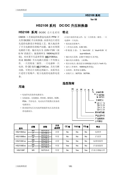
HS2108 系列 DC/DC 升压转换器
HS2108 系 列 DC/DC 芯片是 采用 特点
CMOS 工艺制造的低静态电流的 PFM 开 关型 DC/DC 升压转换器。该系列芯片采用 先进的电路设计和制造工艺,极大地改善 了开关电路固有的噪声问题,减小对周围 电路的干扰。输出电压为 2.0V~7.0V(按 0.1V 的级差),振荡频率为 180KHz(典型 值)。对内置开关晶体管的 ME2108Xxx, 组成 DC/DC 升压电路只需接三个外围元 件, 一只肖特基二极管、一只电感和一只 电容。带 CE 端的 ME2108Cxx,具有关断 功能,可使芯片功耗达到最小。该系列芯 片适用于低噪声、较大电流的电池供电设 备。
Vout=VLX=6V
Vout=set Vout*0.95 on(VLX“L”)side
HS2108 系列
Ver 08
最小 3.22
数值 典型 3.30 0.8
0.45
80 10 360
180 84 85
最大 3.38 0.9
0.5
单位
V V
V
µA µA mA µA kHz % %
注意:1、Diode 采用肖特基二极管(正向压降约 0.2V),如 IN5817,IN5819 2、电感采用:33μH(r<0.1Ω) 3、电容采用钽电容,100μF。
•只需少量的外接元件:仅一只肖特基二极管、一只 电感和一只电容; • 低纹波及低噪声; • 工作电压范围:0.9V~8V; • 带 载 能 力 强 : 当 Vin=3.0V 且 Vout=5.0V 时
Iout=400mA; • 输出电压范围:2.0V~7.0V(步长 0.1V); • 输出电压高精度:±2.5%; • 低启动电压:最高值为 0.9V(输出电流为 1mA 时); • 最大工作频率:180KHz(典型值); • 高效率:典型值为 83%; • 封装尺寸:SOT23,SOT89。
Silicon Laboratories CP2108-EK 评估板用户指南说明书
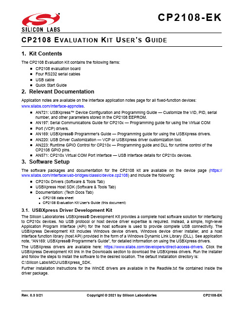
Rev. 0.3 3/21Copyright © 2021 by Silicon LaboratoriesCP2108-EK1. Kit ContentsThe CP2108 Evaluation Kit contains the following items:⏹ CP2108 evaluation board ⏹ Four RS232 serial cables ⏹ USB cable ⏹ Quick Start Guide2. Relevant DocumentationApplication notes are available on the Interface application notes page for all fixed-function devices:/interface-appnotes .⏹ AN721: USBXpress™ Device Configuration and Programming Guide — Customize the VID, PID, serialnumber, and other parameters stored in the CP2108 EEPROM.⏹ AN197: Serial Communications Guide for CP210x — Programming guide for using the Virtual COM ⏹ Port (VCP) drivers.⏹ AN169: USBXpress® Programmer's Guide — Programming guide for using the USBXpress drivers.⏹ AN220: USB Driver Customization — VCP or USBXpress driver customization tool.⏹ AN223: Runtime GPIO Control for CP210x — Programming guide and DLL for runtime control of the CP2108 GPIO pins.⏹ AN571: CP210x Virtual COM Port Interface — USB interface details for CP210x devices.3. Software SetupThe software packages and documentation for the CP2108 kit are available on the device page (https:///interface/usb-bridges/classic/device.cp2108) and include the following:⏹ CP210x Drivers (Software & Tools Tab)⏹ USBXpress Host SDK (Software & Tools Tab)⏹ Documentation: (Tech Docs Tab)● CP2108 data sheet● CP2108 Evaluation Kit User's Guide (this document)3.1. USBXpress Driver Development KitThe Silicon Laboratories USBXpress® Development Kit provides a complete host software solution for interfacing to CP210x devices. No USB protocol or host device driver expertise is required. Instead, a simple, high-level Application Program Interface (API) for the host software is used to provide complete USB connectivity. The USBXpress Development Kit includes Windows device drivers, Windows device driver installer, and a host interface function library (host API) provided in the form of a Windows Dynamic Link Library (DLL). See application note, “AN169: USBXpress® Programmer's Guide”, for detailed information on using the USBXpress drivers.The USBXpress drivers are available here: https:///developers/direct-access-drivers . Click the USBXpress Development Kit link in the Downloads section to download the USBXpress drivers. Run the installer and follow the steps to install the software to the desired location. The default installation directory is: C:\Silicon Labs\MCU\USBXpress_SDK.Further installation instructions for the WinCE drivers are available in the ReadMe.txt file contained inside the driver package.CP2108-EK4. CP2108 Hardware InterfaceConnect the CP2108 evaluation board to a PC as shown in Figure1.1. Connect one end of the USB cable to a USB Port on the PC.2. Connect the other end of the USB cable to the USB connector on the CP2108 evaluation board.3. Connect one end of the RS232 serial cable to one of the DB9 connectors on the CP2108 evaluation board.4. Connect the other end of the RS232 serial cable to the target serial device.5. To connect to additional serial devices, repeat Steps 3 and 4 using another RS232 serial cable and one ofthe unused DB9 connectors on the CP2108 evaluation board.Figure1.Hardware SetupCP2108-EK5. CP2108 Software InterfaceIf the Virtual COM Port drivers are used, the CP2108 will appear as four COM ports in the Device Manager, as shown in Figure 2. The CP2108 will always use the lowest available COM ports for operation. For instance, if COM ports 1 through 6 are in use by other peripherals and applications, the CP2108 will use COM 7, COM 8, COM 9and COM 10.The CP2108 functions identically to four COM ports from the reference point of both the host application and the serial devices, and it can support serial device control requests defined in the Microsoft Win32® Communications API. Examples for how to communicate with the device as two serial COM ports are included in application note,“AN197: Serial Communications for the CP210x” on the /interface-appnotespage or in the USBXpress Host SDK.If the USBXpress drivers are used, the CP2108 will appear as four USB USBXpress devices as shown in Figure 3.The USBXpress driver must be customized using application note, “AN220: USB Driver Customization”. Examples for how to communicate with the device using the USBXpress interface are included in application note, “AN169:USBXpress Programmer’s Guide”, on the /interface-appnotes page.Figure 2.CP210x in Device Manager Using the VCP DriverCP2108-EKFigure 3.CP210x in Device Manager Using the USBXpress DriverCP2108-EK 6. Target BoardThe CP2108 Evaluation Kit includes an evaluation board with a CP2108 device pre-installed for evaluation and pre-liminary software development. Numerous input/output (I/O) connections are provided to facilitate prototyping using the evaluation board. Refer to Figure4 for the locations of the various I/O connectors.P0-3 DB9 connectors for the RS232 interfaceP4 USB connector for USB interfaceJ0-3 UART signal access connectorJ4 SUSPEND LED connectorDS8 Red SUSPEND indicator LEDJ5 Board Power Selector (bus- or self-powered)J6 GPIO0-7 LED ConnectorJ7 GPIO8-15 Rx/Tx Toggle PinsJ8 VBUS Pin Connection for current measurementsJ9 +3V/VDD Connector OptionJ10 VIO/VDD Connector OptionJ11 NC Pins, GNDDS0-DS7 Green GPIO LEDsP4J5Figure4.CP2108 Evaluation Board with Default Shorting Blocks InstalledCP2108-EK6.1. DB9 Connector for RS232 Interface (P0-P3, J0-J3)Four RS232 transceiver circuits and DB9 connectors (P0-3) are provided on the evaluation board to connect the CP2108 virtual serial ports to external serial devices. The headers J0-3 connect the CP2108 pins to the DB9connectors and provide access to the RS232 signals. See Table 1 for the RS232 P0-3 pin descriptions and Table 2 for J0, J1, J2, J3 pin descriptions.6.2. Board Power Selector (J5)This header (J5) provides bus- or self-powered options for the CP2108 device.⏹ Pins 1-2 connect USB connector VBUS (P4) to the VREGIN pin on the CP2108 and puts the device in buspowered mode. The voltage regulator output appears on the VDD pin (pin 3).⏹ Pins 2-3 connect the CP2108 VREGIN to the CP2108 VDD pin and puts the device in self-powered mode. This bypasses the voltage regulator. A voltage of 1.8 to 3.6V power must be supplied to the VDD pin.6.3. Power Connectors (J9, J10)The J9 and J10 headers are included on the evaluation board to provide several power options.⏹ J9 connects the main +3V net to the CP2108 VDD pin. The VDD pin is the output of the on-chip regulator.The main +3V net powers the other components (green LEDs and RS-232 transceivers) on the board. It can be disconnected using J9 for current measurement purposes.⏹ J10 connects the CP2108 VIO input to the CP2108 VDD pin. Remove the shorting block to power VIO from an external source.Table 1. RS232 Connector (P0-3) Pin Descriptions PinSignalCP2108 DirectionDescription1DCD Input Data Carrier Detect 2RXD Input Receive Data 3TXD Output Transmit Data 4DTR Output Data Terminal Ready5GND Ground 6DSR Input Data Set Ready 7RTS Output Request to Send 8CTS Input Clear to Send 9RIInputRing IndicatorTable 2. RS232 Header (J0-3) Pin Descriptions PinsSignalCP2108 DirectionDescription1-2TXD Output Transmit Data 3-4RXD Input Receive Data 5-6DTR Output Data Terminal Ready7-8RI Input Ring Indicator 9-10DCD Input Data Carrier Detect 11-12DSR Input Data Set Ready 13-14CTS Input Clear to Send 15-16RTSOutputRequest to SendCP2108-EK6.4. VBUS Connector (J8)The VBUS connector J8 connects the VBUS pin on the USB connector (P4) to the CP2108 VBUS pin. If the jumper is removed and a multimeter is inserted, the power consumption can be measured.6.5. GPIO.0-7 LED Header (J6)Place shorting blocks on J6 to connect the GPIO.0–7 pins to the eight green LEDs (DS0-DS7). These LEDs can be used to indicate active communications through the CP2108. Table3 shows the LED corresponding to each header position. When using the CP2108 in modem mode, the shorting blocks on J6 should be removed.Table 3. J6LED LocationsLED J6 PinsDS01-2DS13-4DS25-6DS37-8DS49-10DS511-12DS613-14DS715-166.6. GPIO.8-15 Header (J7)The J7 header allows access to the GPIO.8-15 pins on the CP2108. These GPIO pins may be connected to the LEDs using J6 or used for alternate functions described in the CP2108 data sheet.6.7. Universal Serial Bus (USB) Interface (P4)A Universal Serial Bus (USB) connector (P4) is provided to facilitate connections to the USB interface on the CP2108. See Table4 for the USB pin definitions.Table 4. USB Connector Pin DescriptionsPin #Description1VBUS2D-3D+4GND (Ground)6.8. SUSPEND LED Header (J4)The J4 header enables the DS8 LED on the SUSPEND output pin on the CP2108.CP2108-EKCP2108-EKD OCUMENT C HANGE L ISTRevision 0.2 to Revision 0.3⏹Removed section “1. Introduction".⏹Added section "2. Relevant Documentation".⏹Updated section "3. Software Setup" to point to new hyperlink for the drivers on the website.⏹Added section "3.1. USBXpress Driver Development Kit"⏹Updated section "5. CP2108 Software Interface"⏹Added "Figure 3: CP210x in Device Manager Using the USBXpress Driver”⏹Changed section "6. Detailed Hardware Description" to "6.Target Board"。
广州市博士科技有限公司817D型光电转换器产品说明书

Dimensions: [mm]2112Scale - 3:1Würth Elektronik eiSos GmbH & Co. KG EMC & Inductive Solutions Max-Eyth-Str. 174638 Waldenburg Germany140817141410Würth Elektronik eiSos GmbH & Co. KGEMC & Inductive Solutions140817141410 Max-Eyth-Str. 174638 WaldenburgGermanyTotal Power Dissipation vs. Ambient Temperature:20406080100120140160-55-35-15525456585105125IR-diode -I F(mA)Ambient Temperature (°C)Phototransistor-PO(mW)CollectorPowerDissipation(mW)ForwardCurrent(mA)Collector Dark Current vs. Ambient Temperature:11010010001000025456585105125CollectorDarkCurrent(nA)Ambient Temperature (°C)V CE= 20VV CE= 10VNote: measured with Bin BWürth Elektronik eiSos GmbH & Co. KGEMC & Inductive SolutionsMax-Eyth-Str. 174638 WaldenburgGermanyCHECKED REVISION DATE (YYYY-MM-DD)GENERAL TOLERANCE PROJECTIONMETHODSaVo001.0052023-08-22DIN ISO 2768-1mDESCRIPTIONWL-OCPT OptocouplerPhototransistor ORDER CODE140817141410SIZE/TYPE BUSINESS UNIT STATUS PAGEAbsolute CTR vs. Ambient Temperature50100150200250300-60-40-20020406080100120AbsoluteCTRAmbient Temperature (°C)V CE= 5VV CE= 0,4VTestcondition: I F=5mA, T A=25°C, Bin BRelative CTR vs. Ambient Temperature:0,40,60,811,21,4-60-40-20020406080100120RelativeCTRAmbient Temperature (°C)V CE= 5VV CE= 0,4VTestcondition: I F=5mA, Normalized to T A=25°C, Bin BWürth Elektronik eiSos GmbH & Co. KGEMC & Inductive SolutionsMax-Eyth-Str. 174638 WaldenburgGermanyCHECKED REVISION DATE (YYYY-MM-DD)GENERAL TOLERANCE PROJECTIONMETHODSaVo001.0052023-08-22DIN ISO 2768-1mDESCRIPTIONWL-OCPT OptocouplerPhototransistor ORDER CODE140817141410SIZE/TYPE BUSINESS UNIT STATUS PAGEWürth Elektronik eiSos GmbH & Co. KGEMC & Inductive Solutions140817141410 Max-Eyth-Str. 174638 WaldenburgGermanyWürth Elektronik eiSos GmbH & Co. KGEMC & Inductive Solutions140817141410 Max-Eyth-Str. 174638 WaldenburgGermany050100150200250300350400450A b s o l u t e C T R (%)Testcondition T A Würth Elektronik eiSos GmbH & Co. KG EMC & Inductive Solutions Max-Eyth-Str. 174638 Waldenburg Germany140817141410050100150200250300A b s o l u t e C T R (%)Testcondition T A Würth Elektronik eiSos GmbH & Co. KG EMC & Inductive Solutions Max-Eyth-Str. 174638 Waldenburg Germany1408171414100102030R e s p o n s e T i m e (µs )Testcondition I C Würth Elektronik eiSos GmbH & Co. KG EMC & Inductive Solutions Max-Eyth-Str. 174638 Waldenburg Germany140817141410Würth Elektronik eiSos GmbH & Co. KGEMC & Inductive Solutions140817141410 Max-Eyth-Str. 174638 WaldenburgGermanyWürth Elektronik eiSos GmbH & Co. KGEMC & Inductive Solutions140817141410 Max-Eyth-Str. 174638 WaldenburgGermanyT e m p e r a t u r eT T T Würth Elektronik eiSos GmbH & Co. KG EMC & Inductive Solutions Max-Eyth-Str. 174638 Waldenburg Germany140817141410Cautions and Warnings:The following conditions apply to all goods within the product series of Optoelectronic Components of Würth Elektronik eiSos GmbH & Co. KG:General:•This optoelectronic component is designed and manufactured for use in general electronic equipment.•Würth Elektronik must be asked for written approval (following the PPAP procedure) before incorporating the components into any equipment in fields such as military, aerospace, aviation, nuclear control, submarine, transportation (automotive control, train control,ship control), transportation signal, disaster prevention, medical, public information network, etc. where higher safety and reliability are especially required and/or if there is the possibility of direct damage or human injury.•Optoelectronic components that will be used in safety-critical or high-reliability applications, should be pre-evaluated by the customer. •The optoelectronic component is designed and manufactured to be used within the datasheet specified values. If the usage and operation conditions specified in the datasheet are not met, the wire insulation may be damaged or dissolved. •Do not drop or impact the components, the component may be damaged•Würth Elektronik products are qualified according to international standards, which are listed in each product reliability report. Würth Elektronik does not warrant any customer qualified product characteristics beyond Würth Elektroniks’ specifications, for its validity and sustainability over time.•The responsibility for the applicability of the customer specific products and use in a particular customer design is always within the authority of the customer. All technical specifications for standard products also apply to customer specific products.•Unless Würth Elektroik has given its express consent, the customer is under no circumstances entitled to reverse engineer, disassemble or otherwise attempt to extract knowledge or design information from the optoelectronic component.Product specific:Soldering:•The solder profile must comply with the technical product specifications. All other profiles will void the warranty. •All other soldering methods are at the customers’ own risk•The soldering pad pattern shown above is a general recommendation for the easy assembly of optoelectronic components. If a high degree of precision is required for the selected application (i.e. high density assembly), the customer must ensure that the soldering pad pattern is optimized accordingly.Cleaning and Washing:•Washing agents used during the production to clean the customer application might damage or change the characteristics of the optoelectronic component body, marking or plating. Washing agents may have a negative effect on the long-term functionality of the product.• Using a brush during the cleaning process may break the optoelectronic component body. Therefore, we do not recommend using a brush during the PCB cleaning process.Potting:•If the product is potted in the customer application, the potting material might shrink or expand during and after hardening. Shrinking could lead to an incomplete seal, allowing contaminants into the optoelectronic component body, pins or termination. Expansion could damage the components. We recommend a manual inspection after potting to avoid these effects.Storage Conditions:• A storage of Würth Elektronik products for longer than 12 months is not recommended. Within other effects, the terminals may suffer degradation, resulting in bad solderability. Therefore, all products shall be used within the period of 12 months based on the day of shipment.•Do not expose the optoelectronic component to direct sunlight.•The storage conditions in the original packaging are defined according to DIN EN 61760-2.•For a moisture sensitive component, the storage condition in the original packaging is defined according to IPC/JEDEC-J-STD-033. It is also recommended to return the optoelectronic component to the original moisture proof bag and reseal the moisture proof bag again. •The storage conditions stated in the original packaging apply to the storage time and not to the transportation time of the components.Packaging:•The packaging specifications apply only to purchase orders comprising whole packaging units. If the ordered quantity exceeds or is lower than the specified packaging unit, packaging in accordance with the packaging specifications cannot be ensured.Handling:•Violation of the technical product specifications such as exceeding the nominal rated current, will void the warranty. •The product design may influence the automatic optical inspection.•Certain optoelectronic component surfaces consist of soft material. Pressure on the top surface has to be handled carefully to prevent negative influence to the function and reliability of the optoelectronic components.•ESD prevention methods need to be applied for manual handling and processing by machinery. •Resistors for protection are obligatory.•In addition to optoelectronic components testing, products incorporating these devices have to comply with the safety precautions given in IEC 60825-1, IEC 62471 and IEC 62778.Technical specification:•The typical and/or calculated values and graphics of technical parameters can only reflect statistical figures. The actual parameters ofeach single product, may differ from the typical and/or calculated values or the typical characteristic line.Würth Elektronik eiSos GmbH & Co. KG EMC & Inductive Solutions Max-Eyth-Str. 174638 Waldenburg GermanyCHECKED REVISION DATE (YYYY-MM-DD)GENERAL TOLERANCEPROJECTION METHODSaVo001.0052023-08-22DIN ISO 2768-1mDESCRIPTIONWL-OCPT Optocoupler PhototransistorORDER CODE140817141410SIZE/TYPEBUSINESS UNITSTATUSPAGE•In the characteristics curves, all values given in dotted lines may show a higher deviation than the paramters mentioned above. •On each reel, only one bin is sorted and taped. The bin is defined on the current transfer ratio.•In order to ensure highest availability, the reel binning of standard deliveries can vary. A single bin cannot be ordered. Please contact us in advance, if you need a particular bin sorting before placing your order.•These cautions and warnings comply with the state of the scientific and technical knowledge and are believed to be accurate and reliable. However, no responsibility is assumed for inaccuracies or incompleteness.The customer has the sole responsibility to ensure that he uses the latest version of this datasheet, which is available on Würth Elektronik’s homepage. Unless otherwise agreed in writing (i.e. customer specific specification), changes to the content of this datasheet may occurwithout notice, provided that the changes do not have a significant effect on the usability of the optoelectronic components.Würth Elektronik eiSos GmbH & Co. KG EMC & Inductive Solutions Max-Eyth-Str. 174638 Waldenburg GermanyCHECKED REVISION DATE (YYYY-MM-DD)GENERAL TOLERANCEPROJECTION METHODSaVo001.0052023-08-22DIN ISO 2768-1mDESCRIPTIONWL-OCPT Optocoupler PhototransistorORDER CODE140817141410SIZE/TYPEBUSINESS UNITSTATUSPAGEImportant NotesThe following conditions apply to all goods within the product range of Würth Elektronik eiSos GmbH & Co. KG:1. General Customer ResponsibilitySome goods within the product range of Würth Elektronik eiSos GmbH & Co. KG contain statements regarding general suitability for certain application areas. These statements about suitability are based on our knowledge and experience of typical requirements concerning the areas, serve as general guidance and cannot be estimated as binding statements about the suitability for a customer application. The responsibility for the applicability and use in a particular customer design is always solely within the authority of the customer. Due to this fact it is up to the customer to evaluate, where appropriate to investigate and decide whether the device with the specific product characteristics described in the product specification is valid and suitable for the respective customer application or not.2. Customer Responsibility related to Specific, in particular Safety-Relevant ApplicationsIt has to be clearly pointed out that the possibility of a malfunction of electronic components or failure before the end of the usual lifetime cannot be completely eliminated in the current state of the art, even if the products are operated within the range of the specifications.In certain customer applications requiring a very high level of safety and especially in customer applications in which the malfunction or failure of an electronic component could endanger human life or health it must be ensured by most advanced technological aid of suitable design of the customer application that no injury or damage is caused to third parties in the event of malfunction or failure of an electronic component. Therefore, customer is cautioned to verify that data sheets are current before placing orders. The current data sheets can be downloaded at .3. Best Care and AttentionAny product-specific notes, cautions and warnings must be strictly observed. Any disregard will result in the loss of warranty.4. Customer Support for Product SpecificationsSome products within the product range may contain substances which are subject to restrictions in certain jurisdictions in order to serve specific technical requirements. Necessary information is available on request. In this case the field sales engineer or the internal sales person in charge should be contacted who will be happy to support in this matter.5. Product R&DDue to constant product improvement product specifications may change from time to time. As a standard reporting procedure of the Product Change Notification (PCN) according to the JEDEC-Standard inform about minor and major changes. In case of further queries regarding the PCN, the field sales engineer or the internal sales person in charge should be contacted. The basic responsibility of the customer as per Section 1 and 2 remains unaffected.6. Product Life CycleDue to technical progress and economical evaluation we also reserve the right to discontinue production and delivery of products. As a standard reporting procedure of the Product Termination Notification (PTN) according to the JEDEC-Standard we will inform at an early stage about inevitable product discontinuance. According to this we cannot guarantee that all products within our product range will always be available. Therefore it needs to be verified with the field sales engineer or the internal sales person in charge about the current product availability expectancy before or when the product for application design-in disposal is considered. The approach named above does not apply in the case of individual agreements deviating from the foregoing for customer-specific products.7. Property RightsAll the rights for contractual products produced by Würth Elektronik eiSos GmbH & Co. KG on the basis of ideas, development contracts as well as models or templates that are subject to copyright, patent or commercial protection supplied to the customer will remain with Würth Elektronik eiSos GmbH & Co. KG. Würth Elektronik eiSos GmbH & Co. KG does not warrant or represent that any license, either expressed or implied, is granted under any patent right, copyright, mask work right, or other intellectual property right relating to any combination, application, or process in which Würth Elektronik eiSos GmbH & Co. KG components or services are used.8. General Terms and ConditionsUnless otherwise agreed in individual contracts, all orders are subject to the current version of the “General Terms and Conditions of Würth Elektronik eiSos Group”, last version available at .Würth Elektronik eiSos GmbH & Co. KGEMC & Inductive SolutionsMax-Eyth-Str. 174638 WaldenburgGermanyCHECKED REVISION DATE (YYYY-MM-DD)GENERAL TOLERANCE PROJECTIONMETHODSaVo001.0052023-08-22DIN ISO 2768-1mDESCRIPTIONWL-OCPT OptocouplerPhototransistor ORDER CODE140817141410SIZE/TYPE BUSINESS UNIT STATUS PAGE。
智能在线双转换备电源说明说明书
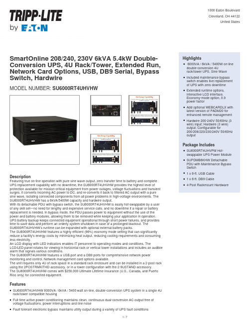
SmartOnline 208/240, 230V 6kVA 5.4kW Double-Conversion UPS, 4U Rack/Tower, Extended Run, Network Card Options, USB, DB9 Serial, Bypass Switch, HardwireMODEL NUMBER:SU6000RT4UHVHWDescriptionFeaturing true on-line operation with pure sine wave output, zero transfer time to battery and complete UPS replacement capability with no downtime, the SU6000RT4UHVHW provides the highest level of protection available for mission-critical equipment from power outages, voltage fluctuations and transient surges. It converts incoming AC power to DC, and re-converts it back to filtered AC output with a pure sine wave, isolating connected components from all power problems in high-voltage environments. The SU6000RT4UHVHW has a 6kVA/5400W capacity and hardwire output.With its detachable PDU with bypass switch, the SU6000RT4UHVHW is easily hot-swappable by a user of any skill set—no need for lengthy and expensive service calls, and no downtime if a repair or battery replacement is needed. In bypass mode, the PDU passes power to equipment without the use of the power and battery modules, allowing them to be removed while keeping your application in operation. UPS battery backup keeps connected equipment operational through short power failures, and provides time to save data and perform an orderly system shutdown in case of a prolonged blackout. TheSU6000RT4UHVHW’s runtime can be expanded with optional external battery packs.The SU6000RT4UHVHW features a highly efficient (96%) economy mode setting that can significantly reduce a facility's energy costs by minimizing heat output, reducing cooling requirements and consuming less electricity.An LCD display with LED indicators enables IT personnel to operating modes and conditions. TheLCD/LED panel rotates for viewing in horizontal rack or vertical tower installations and includes an audible alarm that signals various conditions.The SU6000RT4UHVHW features a USB port and a DB9 ports for comprehensive network power monitoring and control. Network management card options available.The unit requires only 4U of rack space in a standard rack enclosure and can be installed in a 2-post rack using the 2POSTRMKITHD accessory, or in a tower configuration with the 2-9USTAND accessory.The SU6000RT4UHVHW comes with $250,000 Ultimate Lifetime Insurance (U.S., Canada, and Puerto Rico only) for connected equipment.FeaturesSU6000RT4UHVHW 6000VA / 6kVA / 5400 watt on-line, double-conversion UPS system in a single 4U rack/tower compatible housingqFull-time active power conditioning maintains clean, continuous dual-conversion AC output free of voltage fluctuations, power interruptions and line noiseqFault tolerant electronic bypass maintains utility output during a variety of UPS fault conditionsq Highlights6000VA / 6kVA / 5400W on-line double-conversion 4Urack/tower UPS, Sine WaveqIncluded maintenance bypassswitch enables live replacement of UPS with zero downtimeqExtended runtime options,Interactive LCD interface,Economy-mode option, 0.9power factorqAdd optional WEBCARDLX with latest version of PADM20 forenhanced remote management qHardwire 200-240V 50/60Hz (3wire) input; Hardwire (3 wire)output; Configurable for200/208/220/230/240V 50/60Hz outputqPackage IncludesSU6000RT4UHVPM Hot-swappable UPS Power Module qSUPDMB6KHW DetachablePDU with Maintenance BypassSwitchq1 x 6-ft. USB Cableq1 x 6-ft. DB9 Cableq4-Post Rackmount HardwareqDetachable back panel PDU contains hardwire input and output connections, plus manual bypassqswitch to support hot-swappable whole UPS replacement with no interruption to connected equipment Hardwire input and output connections supportedqIncluded rail kit supports 4U 19-inch rack-mount installation in 4-post racksqOptional 2POSTRMKITHD supports installation in 2-post 19-inch racks (1 required forqSU6000RT4UHVHW)Optional 2-9USTAND supports upright tower placement (1 required for SU6000RT4UHVHW)qMaximum installed rack depth of only 20.7 in. / 52.6cm inchesqMaintains full-time sine wave output within 2% of selected 200/208/220/230/240V nominal in doubleqconversion modeCorrects brownouts to 156V at full load (100V at 50% load or less)qCorrects overvoltages to 290V at full load (300V at 90% load or less)qSupports 50/60 Hz operation for worldwide frequency compatibilityqDouble-conversion operation offers full-time AC to DC, then DC to AC conversion to maintain perfectly qregulated sine wave AC output with enhanced protection from harmonic distortion, fast electrical impulses and other hard-to-solve power problems not addressed by other UPS typesHigh efficiency ECONOMY MODE operation significantly reduces BTU heat output and operatingqenergy costsNetwork-grade AC surge and noise suppressionqSupports detailed monitoring of equipment load levels, self-test data and utility power conditions viaqbuilt-in RS-232, USB and network management card optionsCompatible with UPS management card options TLNETCARD, WEBCARDLX, SNMPWEBCARD,qMODBUSCARD and RELAYIOCARDOptional WEBCARDLX (sold separately) with the latest version of PowerAlert Device Manager firmware q(PADM20) provides enhanced remote management capabilitiesPADM20 and PowerAlert Element Manager (PAEM) form a powerful tool for expanding maintenanceqfunctions in large installations, including firmware update checks and backup and restoration of device configurationsOptional RELAYIOMINI interface module offers three configurable hard contact closure outputs forqcustom event notification (requires removal of USB interface module)HID-compliant USB interface enables integration with built-in power management and auto shutdownqfeatures of Windows and macOSUSB & Serial ports enable data-saving unattended shutdown when used with PowerAlert software,qavailable via FREE download from /products/power-alertFront panel LEDs and LCD readout with scroll controls support front-panel visual monitoring of all major qUPS functions with support for a variety of control options to support advanced UPS settings andqconfigurationsLED/LCD display panel rotates for viewing in rack-mount or tower configurationsqSupports Emergency Power Off (EPO) via built-in interfaceqBattery independent restart ensures automatic UPS power-up without user interaction after lengthyqpower outages, even when batteries are expired and require replacementBP192V12-3U external battery packs are field replaceable and hot swappableqIntelligent battery management system with temperature-compensated charging extends battery lifeqSome external battery configurations require the use of External Battery Configuration Software (seeqmanual)Frequency conversion mode enables conversion of 60 Hz to 50Hz or 50Hz to 60 Hz (no de-rating)qSpecificationsPrimary Form Factor RackmountRack Height4UCooling Method FansIncluded Mounting AccessoryDescription 4 post rackmount installation accessories includedInstallation Form Factors Supportedwith Included Accessories 4 post 19 inch rackmountInstallation Form Factors Supported with Optional Accessories 2 post rackmount ( <a class="productLink" href="///2-Post-Rack-Mount-Installation-Kit-3U-Larger-UPS-Transformer-Battery-Pack-Components~2POSTRMKITHD">2POSTRMKITHD</a> ); Tower ( <a class="productLink" href="///2U-9U-Tower-Stand-Kit-select-Rack-Mount-UPS-Systems~2-9USTAND">2-9USTAND</a> )Maximum Device Depth (cm)52.58Maximum Device Depth (in.)20.7Maximum Device Depth (mm)526Minimum Required Rack Depth (cm)60.96Minimum Required Rack Depth(inches)24Minimum Required Rack Depth withExternal Battery Pack (cm)74Minimum Required Rack Depth withExternal Battery Pack (in.)29Minimum Required Rack Depthwithout External Battery Pack (cm)53Minimum Required Rack Depthwithout External Battery Pack (in.)20.75Primary UPS Depth (mm)525Primary UPS Height (mm)174Primary UPS Width (mm)445Shipping Dimensions (hwd / in.)12.70 x 23.60 x 29.10 Shipping Dimensions (hwd / cm)32.26 x 59.94 x 73.91 Shipping Weight (lbs.)156.50Shipping Weight (kg)70.99UPS Housing Material SteelUPS Power Module Dimensions(hwd, cm)17.40 x 44.45 x 52.50UPS Power Module Dimensions(hwd, in.) 6.85 x 17.5 x 20.67 UPS Power Module Weight (kg)52.71UPS Power Module Weight (lbs.)116.2Unit Dimensions (hwd / in.) 6.850 x 17.500 x 20.670 Unit Weight (lbs.)116.200© 2023 Eaton. All Rights Reserved. Eaton is a registered trademark. All other trademarks are the property of their respective owners.。