电气外文文献翻译
电气外文文献 翻译
Circuit breaker断路器Compressed air circuit breaker is a mechanical switch equipment, can be i 空气压缩断路器是一种机械开关设备,能够在n normal and special conditions breaking current (such as short circuit cur 正常和特殊情况下开断电流(比如说短路电流)。
rent). For example, air circuit breaker, oil circuit breaker, interference circ 例如空气断路器、油断路器,干扰电路的导体uit conductor for the application of the safety and reliability of the circuit 干扰电路的导体因该安全可靠的应用于其中,breaker, current in arc from is usually divided into the following grades: a 电流断路器按灭弧远离通常被分为如下等级:ir switch circuit breaker, oil circuit breaker, less oil circuit breaker, compr 空气开关断路器、油断路器、少油断路器、压缩空essed air circuit breaker, a degaussing of isolating switch, six sulfur hexaf 气断路器、具有消磁性质的隔离开关、六氟luoride circuit breaker and vacuum breaker. Their parameters of voltage, 化硫断路器和真空断路器。
他们的参数有电压等级、current, insulation level of breaking capacity, instantaneous voltage off ti 开断容量的电流、绝缘等级开断时间的瞬时电压恢复和me of recovery and a bombing. Breaker plate usually include: 1 the maxi 轰炸时间。
电气工程及其自动化专业_外文文献_英文文献_外文翻译_plc方面.
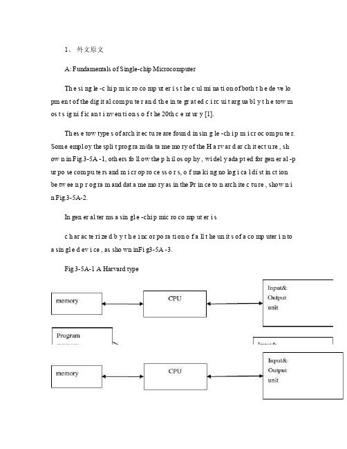
1、外文原文A: Fundamentals of Single-chip MicrocomputerTh e si ng le -c hi p m ic ro co mp ut er i s t he c ul mi na ti on of both t h e de ve lo pm en t of the dig it al com pu te r an d th e in te gr at ed c i rc ui t arg ua bl y t h e tow m os t s ig ni f ic an t i nv en ti on s o f t he 20th c e nt ur y [1].Th es e tow type s of arch it ec tu re are foun d in sin g le -ch i p m i cr oc om pu te r. Som e empl oy the spli t prog ra m/da ta me mo ry of the H a rv ar d ar ch it ect u re , sh ow n in Fig.3-5A -1, oth ers fo ll ow the p h il os op hy , wi del y ada pt ed for gen er al -p ur po se com pu te rs and m i cr op ro ce ss o r s, o f ma ki ng no log i ca l di st in ct ion be tw ee n p r og ra m and dat a me mo ry as in the Pr in ce to n arch ite c tu re , show n i n Fig.3-5A-2.In gen er al ter ms a sin gl e -chi p mic ro co mp ut er i sc h ar ac te ri zed b y t he i nc or po ra ti on of a ll t he un it s of a co mp uter i n to a sin gl e d ev i ce , as sho wn inFi g3-5A -3.Fig.3-5A-1 A Harvard typeFig.3-5A-2. A conventional Princeton computerFig3-5A-3. Principal features of a microcomputerRead only memory (ROM.R OM is usua ll y for the pe rm an ent,n o n-vo la ti le stor a ge of an app lic a ti on s pr og ra m .M an ym i cr oc om pu te rs and m are inte nd e d for high -v ol um e ap pl ic at ions a n d he nc e t h e eco n om ic al man uf act u re of th e de vic e s re qu ir es t h at t he cont en t s o f t he prog ra m me m or y be co mm it t ed perm a ne ntly d u ri ng the man ufa c tu re of ch ip s .Cl ea rl y, thi s im pl ie s a r i go ro us app ro ach to ROM cod e deve l op me nt sin ce cha ng es can not b e mad e afte r manu f a c tu re .Th is dev e lo pm en t proc ess may invo lv e e m ul at io n us in g aso ph is ti ca te d de ve lo pm en t sy ste m wit h a h a rd wa re emu la tio n cap ab il it y as w el l as the use o f po we rf ul s o ft wa re too ls.So me man uf act u re rs pro vi de add it io na l RO M opt i on s by i n cl ud in g in their ra n ge dev ic es wit h (or int en de d fo r use wit h u s er pro gr am ma ble me mo ry. Th e sim p le st of th es e is usu al ly d e vi ce whi ch can op er at e in a micro p ro ce ssor mod e by usi ng som e o f the inp ut /outp u t li ne s as an ad dr es s an d da ta b us fora c ce ss in g ex te rna l mem or y. Thi s t y pe of de vi ce can beh av ef u nc ti on al ly as th e sing le chip mi cr oc om pu te r from whi ch it is d e ri ve d al be it wit h re st ri ct ed I/O and a mod if ied ex te rn al c i rc ui t. The use of thes e d ev ic es is com mo n eve n in prod uc ti on c i rc ui ts wher e t he vo lu me does no tj us ti f y t h e d ev el o pm en t c osts o f c us to m o n -ch i p R OM [2];t he re c a n s ti ll bea s ignif i ca nt saving i n I /O and o th er c h ip s com pa re d to a conv en ti on al mi c ro pr oc es sor b a se d ci rc ui t. Mor e ex ac t re pl ace m en t fo r RO M dev i ce s ca n be o b ta in ed in th e fo rm of va ri an ts w it h 'p ig gy -b ack 'E P RO M(Er as ab le pro gr am ma bl e ROM s oc ke ts or dev ic e s with EPROM i n st ea d o f RO M 。
电气工程及其自动化专业 外文文献 英文文献 外文翻译 plc方面

1、外文原文(复印件)A: Fundamentals of Single-chip MicrocomputerTh e si ng le-ch i p mi cr oc om pu ter is t he c ul mi nat i on o f bo th t h e d ev el op me nt o f th e d ig it al com p ut er an d t he int e gr at ed ci rc ui ta r gu ab ly th e t ow m os t s i gn if ic ant i nv en ti on s o f t h e 20t h c en tu ry[1].Th es e to w typ e s of a rc hi te ctu r e ar e fo un d i n s in gl e-ch ip m i cr oc om pu te r. So m e em pl oy t he sp l it p ro gr am/d ata me mo ry o f th e H a rv ar d ar ch it ect u re, sh ow n i n -5A, ot he rs fo ll ow th e ph i lo so ph y, w i de ly a da pt ed fo r g en er al-p ur pos e c om pu te rs an d m i cr op ro ce ss or s, o f m a ki ng no lo gi c al di st in ct io n b e tw ee n p ro gr am a n d da t a m em ory a s i n th e Pr in cet o n ar ch it ec tu re,sh ow n in-5A.In g en er al te r ms a s in gl e-chi p m ic ro co mp ut er i sc h ar ac te ri zed b y the i nc or po ra tio n of al l t he uni t s o f a co mp ut er i n to a s in gl e dev i ce, as s ho wn in Fi g3-5A-3.-5A-1 A Harvard type-5A. A conventional Princeton computerFig3-5A-3. Principal features of a microcomputerRead only memory (ROM).R OM i s u su al ly f or th e p er ma ne nt, n o n-vo la ti le s tor a ge o f an a pp lic a ti on s pr og ra m .M an ym i cr oc om pu te rs an d mi cr oc on tr ol le r s a re in t en de d fo r h ig h-v ol ume a p pl ic at io ns a nd h en ce t he e co nom i ca l ma nu fa ct ure of t he d ev ic es r e qu ir es t ha t the co nt en ts o f the pr og ra m me mo ry b e co mm it te dp e rm an en tl y d ur in g th e m an uf ac tu re o f c hi ps . Cl ear l y, th is im pl ie sa ri g or ou s a pp roa c h t o R OM co de d e ve lo pm en t s in ce c ha ng es ca nn otb e m ad e af te r man u fa ct ur e .T hi s d e ve lo pm en t pr oce s s ma y in vo lv e e m ul at io n us in g a s op hi st ic at ed deve lo pm en t sy st em w i th a ha rd wa re e m ul at io n ca pa bil i ty a s we ll a s th e u se of po we rf ul so ft wa re t oo ls.So me m an uf act u re rs p ro vi de ad d it io na l RO M opt i on s byi n cl ud in g i n th ei r ra ng e de vi ce s wi th (or i nt en de d fo r us e wi th) u s er pr og ra mm ab le m em or y. Th e s im p le st of th es e i s us ua ll y d ev ice w h ic h ca n op er ate in a m ic ro pr oce s so r mo de b y usi n g so me o f th e i n pu t/ou tp ut li ne s as a n ad dr es s an d da ta b us f or acc e ss in g e xt er na l m e mo ry. T hi s t ype o f d ev ic e c an b e ha ve fu nc ti on al l y a s t he si ng le c h ip mi cr oc om pu te r fr om wh ic h i t i s de ri ve d a lb eit w it h r es tr ic ted I/O an d a mo di fie d e xt er na l ci rcu i t. T he u se o f t h es e RO Ml es sd e vi ce s is c om mo n e ve n in p ro du ct io n c ir cu it s wh er e t he v ol um e do es n o t ju st if y th e d e ve lo pm en t co sts of c us to m on-ch i p RO M[2];t he re c a n st il l b e a si g ni fi ca nt s a vi ng in I/O a nd ot he r c hi ps co mp ar ed t o a c on ve nt io nal mi cr op ro ce ss or b as ed c ir cu it. M o re e xa ctr e pl ac em en t fo r RO M d ev ic es c an b e o bt ai ne d in t he f o rm o f va ri an ts w i th 'pi gg y-ba ck'EP RO M(Er as ab le p ro gr am ma bl e ROM)s oc ke ts o rd e vi ce s w it h EP ROM i ns te ad o f R OM 。
电气 自动化 外文文献 外文翻译 英文文献
外文出处:Farhadi, A. (2008). Modeling, simulation, and reduction of conducted electromagnetic interference due to a pwm buck type switching power supply. Harmonics and Quality of Power, 2008. ICHQP 2008. 13th International Conference on, 1 - 6.Modeling, Simulation, and Reduction of Conducted Electromagnetic Interference Due to a PWM Buck Type Switching Power Supply IA. FarhadiAbstract:Undesired generation of radiated or conducted energy in electrical systems is called Electromagnetic Interference (EMI). High speed switching frequency in power electronics converters especially in switching power supplies improves efficiency but leads to EMI. Different kind of conducted interference, EMI regulations and conducted EMI measurement are introduced in this paper. Compliancy with national or international regulation is called Electromagnetic Compatibility (EMC). Power electronic systems producers must regard EMC. Modeling and simulation is the first step of EMC evaluation. EMI simulation results due to a PWM Buck type switching power supply are presented in this paper. To improve EMC, some techniques are introduced and their effectiveness proved by simulation.Index Terms:Conducted, EMC, EMI, LISN, Switching SupplyI. INTRODUCTIONFAST semiconductors make it possible to have high speed and high frequency switching in power electronics []1. High speed switching causes weight and volume reduction of equipment, but some unwanted effects such as radio frequency interference appeared []2. Compliance with electromagnetic compatibility (EMC) regulations is necessary for producers to present their products to the markets. It is important to take EMC aspects already in design phase []3. Modeling and simulation is the most effective tool to analyze EMC consideration before developing the products. A lot of the previous studies concerned the low frequency analysis of power electronics components []4[]5. Different types of power electronics converters are capable to be considered as source of EMI. They could propagate the EMI in both radiated and conducted forms. Line Impedance Stabilization Network (LISN) is required for measurement and calculation of conducted interference level []6. Interference spectrum at the output of LISN is introduced as the EMC evaluation criterion []7[]8. National or international regulations are the references forthe evaluation of equipment in point of view of EMC []7[]8.II. SOURCE, PATH AND VICTIM OF EMIUndesired voltage or current is called interference and their cause is called interference source. In this paper a high-speed switching power supply is the source of interference.Interference propagated by radiation in area around of an interference source or by conduction through common cabling or wiring connections. In this study conducted emission is considered only. Equipment such as computers, receivers, amplifiers, industrial controllers, etc that are exposed to interference corruption are called victims. The common connections of elements, source lines and cabling provide paths for conducted noise or interference. Electromagnetic conducted interference has two components as differential mode and common mode []9.A. Differential mode conducted interferenceThis mode is related to the noise that is imposed between different lines of a test circuit by a noise source. Related current path is shown in Fig. 1 []9. The interference source, path impedances, differential mode current and load impedance are also shown in Fig. 1.B. Common mode conducted interferenceCommon mode noise or interference could appear and impose between the lines, cables or connections and common ground. Any leakage current between load and common ground couldbe modeled by interference voltage source.Fig. 2 demonstrates the common mode interference source, common mode currents Iandcm1 and the related current paths[]9.The power electronics converters perform as noise source Icm2between lines of the supply network. In this study differential mode of conducted interference is particularly important and discussion will be continued considering this mode only.III. ELECTROMAGNETIC COMPATIBILITY REGULATIONS Application of electrical equipment especially static power electronic converters in different equipment is increasing more and more. As mentioned before, power electronics converters are considered as an important source of electromagnetic interference and have corrupting effects on the electric networks []2. High level of pollution resulting from various disturbances reduces the quality of power in electric networks. On the other side some residential, commercial and especially medical consumers are so sensitive to power system disturbances including voltage and frequency variations. The best solution to reduce corruption and improve power quality is complying national or international EMC regulations. CISPR, IEC, FCC and VDE are among the most famous organizations from Europe, USA and Germany who are responsible for determining and publishing the most important EMC regulations. IEC and VDE requirement and limitations on conducted emission are shown in Fig. 3 and Fig. 4 []7[]9.For different groups of consumers different classes of regulations could be complied. Class Afor common consumers and class B with more hard limitations for special consumers are separated in Fig. 3 and Fig. 4. Frequency range of limitation is different for IEC and VDE that are 150 kHz up to 30 MHz and 10 kHz up to 30 MHz respectively. Compliance of regulations is evaluated by comparison of measured or calculated conducted interference level in the mentioned frequency range with the stated requirements in regulations. In united European community compliance of regulation is mandatory and products must have certified label to show covering of requirements []8.IV. ELECTROMAGNETIC CONDUCTED INTERFERENCE MEASUREMENTA. Line Impedance Stabilization Network (LISN)1-Providing a low impedance path to transfer power from source to power electronics converter and load.2-Providing a low impedance path from interference source, here power electronics converter, to measurement port.Variation of LISN impedance versus frequency with the mentioned topology is presented inFig. 7. LISN has stabilized impedance in the range of conducted EMI measurement []7.Variation of level of signal at the output of LISN versus frequency is the spectrum of interference. The electromagnetic compatibility of a system can be evaluated by comparison of its interference spectrum with the standard limitations. The level of signal at the output of LISN in frequency range 10 kHz up to 30 MHz or 150 kHz up to 30 MHz is criterion of compatibility and should be under the standard limitations. In practical situations, the LISN output is connected to a spectrum analyzer and interference measurement is carried out. But for modeling and simulation purposes, the LISN output spectrum is calculated using appropriate software.基于压降型PWM开关电源的建模、仿真和减少传导性电磁干扰摘要:电子设备之中杂乱的辐射或者能量叫做电磁干扰(EMI)。
电气外文文献及翻译

24.437 电力电子正弦脉宽调制如图1所示,电压源逆变器的开关可以按要求打开和关闭。
用最简单的方法,顶部的开关打开,如果每个周期打开和关闭,则方波的波形结果只有一次。
但是如果改进谐波的数据则在个周期内可以实现多次打开关闭。
图1 简单的电压源逆变器 如图2所示,用最直接的执行方式,所期望的输出电压是通过比较预期的参考波形与高频率的三角载波(调制信号) 生成的,无论直流电压是正还是负,信号电压的输出只根据信号电压是否大于或小于载波波形,要注意的是,在此期间一个三角载波周期的平均电压即信号的振幅加到负载形成正比(假定不变)。
经过一段时间,三角载波的负荷是正比于幅值的信号,在这期间,由此产生的方波包含有在它低频元件所需波形的幅值,也具有较高频率分量在一个载波临近频率的幅值。
需要注意的是,由于PWM 使得总谐波不失真,均方根的平均交流电压波形幅值仍与直流电压相等。
谐波分量只是转移到了更高的平率范围,并由电感式交流系统自动过滤。
当正弦波调制信号的振幅为Am ,三角载波的振幅为Ac 时,它们的调制指数就是m=Am/ Ac 。
因此,控制调制指数控制着输出电压的幅值。
如图3所示,fc/fm=21 ,t=L/R=T/3,T 为基本周期,由于感性元件的存在,高频成分不能明显的传播到交流网络(或负载),所以具有足够高的载波频率。
然而,由于具有较高的载波频率,从而导致在更多的功率损耗。
所以,在电力系统的应用中,通常认为使用2-15kHz 的开关频率最为合适。
此外,在三相系统中,建议使用)(,3N k k f f mc ∈=,使得三个波形对称。
图2 主要的脉宽调制图3 SPWM的fc/fm=48,L/R=T/3如图4所示,该过程是比较合适的,因为在该图中有三角载波,其中没有交集的载体作为信号周期。
然而,这种“超调”在一定量的范围内往往是允许获得更大的交流电压,使电压频谱呈现出差异。
需要注意的是,使用一个额外的比率形成一个反周期超过360°的对称波形。
电气工程及其自动化专业外文文献英文文献外文翻译方面
1、 外文原文(复印件)A: Fundamentals of Single-chip MicrocomputerT h e sin gle -ch ip mi c ro co m p u t e r is t h e cu lm in at io n of b ot h t h e d e ve lo p me nt of t h e d ig ita l co m p u t e r a n d t h e i nte g rated c ircu it a rgu ab l y t h e to w mo st s ign if i cant i nve nt i o n s of t h e 20t h c e nt u ry [1].T h ese to w t yp e s of arch ite ct u re are fo u n d in s in gle -ch ip m i cro co m p u te r. S o m e e mp l oy t h e sp l it p ro gra m /d at a m e m o r y of t h e H a r va rd arch ite ct u re , s h o wn in -5A , ot h e rs fo l lo w t h e p h i lo so p hy, wid e l y ad a p ted fo r ge n e ral -p u rp o se co m p u te rs an d m i cro p ro ce ss o rs , of m a kin g n o l o g i ca l d i st in ct i o n b et we e n p ro gra m an d d ata m e m o r y as in t h e P rin c eto n a rch ite ct u re , sh o wn in -5A.In ge n e ra l te r m s a s in g le -ch ip m ic ro co m p u t e r is ch a ra cte r ized b y t h e in co r p o rat io n of all t h e u n its of a co mp u te r into a s in gle d e vi ce , as s h o w n in F i g3-5A-3.-5A-1A Harvard type-5A. A conventional Princeton computerProgrammemory Datamemory CPU Input& Output unitmemoryCPU Input& Output unitResetInterruptsPowerFig3-5A-3. Principal features of a microcomputerRead only memory (ROM).RO M is u su a l l y fo r t h e p e r m an e nt , n o n -vo lat i le sto rage of an ap p l i cat io n s p ro g ram .M a ny m i c ro co m p u te rs a n d m i cro co nt ro l le rs are inte n d ed fo r h i gh -vo lu m e ap p l i cat io n s a n d h e n ce t h e e co n o m i cal man u fa c t u re of t h e d e vi ces re q u ires t h at t h e co nt e nts of t h e p ro gra m me mo r y b e co mm i ed p e r m a n e nt l y d u r in g t h e m a n u fa ct u re of c h ip s . C lea rl y, t h i s imp l ies a r i go ro u s ap p ro a ch to ROM co d e d e ve lo p m e nt s in ce ch an ges can n o t b e mad e af te r m an u fa ct u re .T h i s d e ve l o p m e nt p ro ces s m ay i nvo l ve e mu l at i o n u sin g a so p h ist icated d e ve lo p m e nt syste m wit h a h ard wa re e mu l at i o n capab i l it y as we ll as t h e u s e of p o we rf u l sof t war e to o l s.So m e m an u fa ct u re rs p ro vi d e ad d it i o n a l ROM o p t io n s b y in clu d in g in t h e i r ran ge d e v ic es w it h (o r inte n d ed fo r u s e wit h ) u se r p ro g ram m a b le m e mo r y. T h e s im p lest of t h e se i s u su a l l y d e v i ce wh i ch can o p e rat e in a m i cro p ro ce s so r mo d e b y u s in g s o m e of t h e in p u t /o u t p u t l in es as an ad d res s a n d d ata b u s fo r a cc es sin g exte rn a l m e m o r y. T h is t yp e o f d e vi ce can b e h ave f u n ct i o n al l y as t h e s in gle ch ip m i cro co m p u t e r f ro m wh i ch it i s d e ri ved a lb e it wit h re st r icted I/O an d a m o d if ied exte rn a l c ircu it. T h e u s e of t h e se RO M le ss d e vi ces i s co mmo n e ve n in p ro d u ct io n circu i ts wh e re t h e vo lu m e d o e s n ot ju st if y t h e d e ve lo p m e nt co sts of cu sto m o n -ch ip ROM [2];t h e re ca n st i ll b e a si gn if i cant sav in g in I/O an d o t h e r ch ip s co m pared to a External Timing components System clock Timer/ Counter Serial I/O Prarallel I/O RAM ROMCPUco nve nt io n al m i c ro p ro ces so r b ased circ u it. M o re exa ct re p l a ce m e nt fo rRO M d e v ice s can b e o b tain ed in t h e fo rm of va ria nts w it h 'p i g g y-b a c k'E P ROM(E rasab le p ro gramm ab le ROM )s o cket s o r d e v ice s w it h E P ROMin stead of ROM 。
电气类外文文献及其翻译--正弦脉宽调制
24.437 Power ElectronicsSinusoidal Pulse width modulationThe switches in the voltage source inverter(See Fig.1)can be turned on and off as required.In the simplest approach,the top switch is turned on If turned on and off only once in each cycle,a square wave waveform results.However,if turned on several times in a cycle an improved har- monic profile may be achieved.Fig 1:Simple V oltage SourcedIn the most straightforward implementation,generation of the desired output voltage is achievedby comparing the desired reference waveform(modulating signal)with a high-frequency triangu- lar…carrier‟wave as depicted schematically in Fig.2.Depending on whether the signal voltage is larger or smaller than the carrier waveform,either the positive or negative dc bus voltage is applied at the output.Note that over the period of one triangle wave,the average voltage appliedto the load is proportional to the amplitude of the signal(assumed constant)during this period.The resulting chopped square waveform contains a replica of the desired waveform in its low fre- quency components,with the higher frequency components being at frequencies of an close to the carrier frequency.Notice that the root mean square value of the ac voltage waveform is still equal to the dc bus voltage,and hence the total harmonic distortion is not affected by the PWM process. The harmonic components are merely shifted into the higher frequency range and are automati- cally filtered due to inductances in the ac system.When the modulating signal is a sinusoid of amplitude Am,and the amplitude of the triangular carrier is Ac,the ratio m=Am/Ac is known as the modulation index.Note that controlling the modulation index therefor controls the amplitude of the applied output voltage.With a sufficiently high carrier frequency(see Fig.3 drawn for fc/fm=21 and t=L/R=T/3;T=period of funda- mental),the high frequency components do not propagate significantly in the ac network(or load) due the presence of the inductive elements.However,a higher carrier frequency does result in a larger number of switchings per cycle and hence in an increased power loss.Typically switching frequencies in the 2-15 kHz range are considered adequate for power systems applications.Alsoin three-phase systems it is advisable to use s so that all three waveforms are symmetric.Fig 2:Princ ipal of Pulse Width ModulationFig.3:SPWM with fc/fm=48,L/R=T/3Note that the process works well for m ≤1.For m >1,there are periods of the triangle wave in which there is no intersection of the carrier and the signal as in Fig.4.However,a certain amountof this“overmodulation”is often allowed in the interest of obtaining a larger ac voltage magni- tude even though the spectral content of the voltage is rendered somewhat poorer.Note that with an odd ratio for fc/fm,the waveform is anti-symmetric over a 360 degree cycle. With an even number,there are harmonics of even order,but in particular also a small dc compo- nent.Hence an even number is not recommended for single phase inverters,particularly for smal ratios of fc/fm.SPWM Spectra:Although the SPWM waveform has harmonics of several orders in the phase voltage waveform, the dominant ones other than the fundamental are of order n and n±2 where n=fc/fm.This is evi- dent for the spectrum for n=15 and m=0.8 shown in Fig.5.Note that if the other two phases are identically generated but 120o apart in phase,the line-line voltage will not have any triplenhar-monics.Hence it is advisable to choose,as then the dominant harmonic willbe eliminated.It is evident from Fig 5b,that the dominant 15th harmonic in Fig.5a is effectively eliminated in the line voltage.Choosing a multiple of 3 is also convenient as then the same trian- gular waveform can be used as the carrier in all three phases,leading to some simplification in hardware.It is readily seen that as the where E is the dc bus voltage,that the rms valueof the output voltage signal is unaffected by the PWM process.This is strictly true for the phase voltage as triplen harmonic orders are cancelled in the line voltage.However,the problematic har- monics are shifted to higher orders,thereby making filtering much easier.Often,the filtering is carried out via the natural high-impedance characteristic of the load.Fig.5:SPWM Harmonic Spectra:n=15,m=0.Selective Harmonic Elimination(also called Optimal PWM)Notice that in the SPWM strategy developed above,a large number of switchings are required, with the consequent associated switching losses.With the method of Selective Harmonic Elimina- tion,only selected harmonics are eliminated with the smallest number of switchings.This method however can be difficult to implement on-line due to computation and memory requirements. For a two level PWM waveform with odd and halfwave symmetries and n chops per quarter cycleas shown in Fig 4,the peak magnitude of the harmonic components including the fundamental,are given byEqn.1:Here is the magnitude of the harmonic and is the primary switching angle.Even har- monics do not show up because of the half-wave symmetry.The n chops in the waveform afford n degrees of freedom.Several control options are thus possi- ble.For example n selected harmonics can be eliminated.Another option which is used here is to eliminate n-1 selected harmonics and use the remaining degree of freedom to control the funda- mental frequency ac voltage.To find theα‟s required to achieve this objective,it is sufficient to set the corresponding h‟s in the above equations to the desired values(0 for the n-1 harmonics to be eliminated and the desired per-unit ac magnitude for the fundamental)and solve for theα‟s.Fig 4:A two-level PWM waveform with odd and halfwave symmEquation 1 can be readily proved by finding the fourier coefficients of the waveform shown inFig.4.In general,for a periodic waveform with period,the Fourier Cosine and Sine Coeffi- cients are given by:Because of the half-cycle symmetry of the waveform of Fig.4,only odd order harmonics exist. Also,it is easy to see that the Fourier Cosine coefficients disappear with the choice of coordinateaxes used.Utilizing the quarter cycle symmetry,the Fourier Sine coefficients become:Substituting the two-valued pwm waveform for,one obtains(see Fig.4):The following example illustrates the use of three chops per quarter cycle which allow for three degrees of freedom.We may use these to eliminate two harmonics and control the magnitude of the fundamental to any desired value:Example:Selective Harmonic Elimination is applied with a view to controlling the fundamental component of voltage to 50V(rms)and eliminating the 3rd and 5th harmonics.The source voltage is 100 V. Calculate the required chopping angles.As three objectives are to be achieved,we need 3 chops.The fundamental,3rd and 5th harmonic magnitudes are given by:We require:翻译24.437电力电子正弦脉宽调制电压源逆变器的开关(见图1)可以按要求打开和关闭。
电气工程的外文文献(及翻译)
电气工程的外文文献(及翻译)文献一:Electric power consumption prediction model based on grey theory optimized by genetic algorithms本文介绍了一种基于混合灰色理论与遗传算法优化的电力消耗预测模型。
该模型使用时间序列数据来建立模型,并使用灰色理论来解决数据的不确定性问题。
通过遗传算法的优化,模型能够更好地预测电力消耗,并取得了优异的预测结果。
此模型可以在大规模电力网络中使用,并具有较高的可行性和可靠性。
文献二:Intelligent control for energy-efficient operation of electric motors本文研究了一种智能控制方法,用于电动机的节能运行。
该方法提供了一种更高效的控制策略,使电动机能够在不同负载条件下以较低的功率运行。
该智能控制使用模糊逻辑方法来确定最佳的控制参数,并使用遗传算法来优化参数。
实验结果表明,该智能控制方法可以显著降低电动机的能耗,节省电能。
文献三:Fault diagnosis system for power transformers based on dissolved gas analysis本文介绍了一种基于溶解气体分析的电力变压器故障诊断系统。
通过对变压器油中的气体样品进行分析,可以检测和诊断变压器内部存在的故障类型。
该系统使用人工神经网络模型来对气体分析数据进行处理和分类。
实验结果表明,该系统可以准确地检测和诊断变压器的故障,并有助于实现有效的维护和管理。
文献四:Power quality improvement using series active filter based on iterative learning control technique本文研究了一种基于迭代研究控制技术的串联有源滤波器用于电能质量改善的方法。
电气英文文献+翻译
POWER SUPPLY AND DISTRIBUTION SYSTEMABSTRACTThe basic function of the electric power system is to transport the electric power towards customers. The l0kV electric distribution net is a key point that connects the power supply with the electricity using on the industry, business and daily-life. For the electric power, allcostumers expect to pay the lowest price for the highest reliability, but don't consider that it's self-contradictory in the co-existence of economy and reliable.To improve the reliability of the power supply network, we must increase the investment cost of the network construction But, if the cost that improve the reliability of the network construction, but the investment on this kind of construction would be worthless if the reducing loss is on the power-off is less than the increasing investment on improving the reliability .Thus we find out a balance point to make the most economic,between the investment and the loss by calculating the investment on power net and the loss brought from power-off.KEYWARDS:power supply and distribution,power distribution reliability,reactive compensation,load distributionTEXTThe revolution of electric power system has brought a new big round construction,which is pushing the greater revolution of electric power technique along with the application of new technique and advanced equipment. Especially, the combination of the information technique and electric power technique, to great ex- tent, has improved reliability on electric quality and electric supply. The technical development decreases the cost on electric construction and drives innovation of electric network. On the basis of national and internatio- nal advanced electric knowledge, the dissertation introduces the research hotspot for present electric power sy- etem as following.Firstly, This dissertation introduces the building condition of distribution automation(DA), and brings forward two typical construction modes on DA construction, integrative mode and fission mode .It emphasize the DA structure under the condition of the fission mode and presents the system configuration, the main station scheme, the feeder scheme, the optimized communication scheme etc., which is for DA research reference.Secondly, as for the (DA) trouble measurement, position, isolation and resume, This dissertation analyzes the changes of pressure and current for line problem, gets math equation by educing phase short circuit and problem position under the condition of single-phase and works out equation and several parameter s U& , s I& and e I& table on problem . It brings out optimized isolation and resume plan, realizes auto isolation and network reconstruction, reduces the power off range and time and improves the reliability of electric power supply through problem self- diagnoses and self-analysis. It also introduces software flow and use for problem judgement and sets a model on network reconstruction and computer flow.Thirdly, electricity system state is estimated to be one of the key techniques in DA realization. The dissertation recommends the resolvent of bad measurement data and structure mistake on the ground of describing state estimate way. It also advances a practical test and judging way on topology mistake in state estimate about bad data test and abnormity in state estimate as well as the problem and effect on bad data from state measure to state estimate .As for real time monitor and control problem, the dissertation introduces a new way to solve them by electricity break and exceptional analysis, and the way has been tested in Weifang DA.Fourthly, about the difficulty for building the model of load forecasting, big parameter scatter limit and something concerned, the dissertation introduces some parameters, eg. weather factor, date type and social environment effect based on analysis of routine load forecasting and means. It presents the way for electricity load forecasting founded on neural network(ANN),which has been tested it’s validity by example and made to be good practical effect.Fifthly, concerning the lack of concordant wave on preve nting concordant wave and non-power compensation and non-continuity on compensation, there is a topology structure of PWM main circuit and nonpower theory on active filter the waves technique and builds flat proof on the ground of Saber Designer and proves to be practical. Meanwhile, it analyzes and designs the way of non-power need of electric network tre- nds and decreasing line loss combined with DA, which have been tested its objective economic benefit throu- gh counting example.Sixthly, not only do the dissertation design a way founded on the magrginal electric price fitted to our present national electric power market with regards to future trends of electric power market in China and fair trade under the government surveillance, that is group competitio n in short-term trade under the way of grouped price and quantity harmony, but also puts forward combination arithmetic, math model of trading plan and safty economical restriction. It can solve the original contradiction between medium and long term contract price and short term competitive price with improvement on competitive percentage and cut down the unfair income difference of electric factory, at the same time, it can optimize the electric limit for all electricfactories and reduce the total purchase charge of electric power from burthen curve of whole electric market network.The distribution network is an important link among the power system. Its neutral grounding mode and operation connects security and stability of the power system directly. At the same time, the problem about neutral grounding is associated with national conditions, natural environment, device fabrication and operation. For example, the activity situation of the thunder and lightning, insulating structure and the peripheral interference will influence the choice of neutral grounding mode Conversely, neutral grounding mode affects design, operation, debugs and developing. Generally in the system higher in grade in the voltage, the insulating expenses account for more sizable proportion at the total price of the equipment. It is very remarkable to bring the economic benefits by reducing the insulating level. Usually such system adopt the neutral directly grounding and adopt the autoreclosing to guarantee power supply reliability. On the contrary, the system which is lower in the voltage adopts neutral none grounding to raise power supply reliability. So it is an important subject to make use of new- type earth device to apply to the distribution network under considering the situation in such factors of various fields as power supply reliability, safety factor, over-voltage factor, the choice of relay protection, investment cost, etc.The main work of this paper is to research and choice the neutral grounding mode of the l0kV distribution network. The neutral grounding mode of the l0kV network mainly adopts none grounding, grounding by arc suppressing coil, grounding by reactance grounding and directly grounding. The best grounding mode is confirmed through the technology comparison. It can help the network run in safety and limit the earth electric arc by using auto-tracking compensate device and using the line protection with the detection of the sensitive small ground current. The paper introduces and analyzes the characteristic of all kind of grounding modes about l0kV network at first. With the comparison with technological and economy, the conclusion is drawn that the improved arc suppressing coil grounding mode shows a very big development potential.Then, this paper researches and introduces some operation characteristics of the arc suppressing coil grounding mode of the l0kV distribution network. And then the paper put emphasis on how to extinguish the earth electric arc effectively by utilizing the resonance principle. This paper combines the development of domestic and international technology and innovative achievement, and introduces the computer earth protection and autotracking compensate device. It proves that the improved arc suppressing coil grounding mode have better operation characteristics in power supply reliability, personal security, security of equipment and interference of communication. The application of the arc suppressing coil grounding mode is also researched in this paper.Finally, the paper summarizes this topic research. As a result of the domination of the arc suppressing coil grounding mode, it should be more popularized and applied in the distribution network in the future.The way of thinking, project and conclusions in this thesis have effect on the research to choose the neutral grounding mode not only in I0kV distribution network but also in other power system..The basic function of the electric power system is to transport the electric power towards customers. The l0kV electric distribution net is a key point that connects the power supply with the electricity using on the industry, business and daily-life. For the electric power, all costumers expect to pay the lowest price for the highest reliability, but don't consider that it's self-contradictory in the co-existence of economy and reliable. To improve the reliability of the power supply network, we must increase the investment cost of the network con- struction But, if the cost that improve the reliability of the network construction, but the investment on this kind of construction would be worthless if the reducing loss is on the power-off is less than the increasing investment on improving the reliability .Thus we find out a balance point to make the most economic, between the investment and the loss by calculating the investment on power net and the loss brought from power-off. The thesis analyses on the economic and the reliable of the various line modes, according to the characteristics various line modes existed in the electric distribution net in foshan..First, the thesis introduces as the different line modes in the l0kV electric distribution net and in some foreign countries. Making it clear tow to conduct analyzing on the line mode of the electric distribution net, and telling us how important and necessary that analyses are.Second, it turns to the necessity of calculating the number of optimization subsection, elaborating how it influences on the economy and reliability. Then by building up the calculation mode of the number of optimization subsection it introduces different power supply projects on the different line modes in brief. Third, it carries on the calculation and analyses towards the reliability and economy of the different line modes of electric distribution net, describing drafts according by the calculation. Then it makes analysis and discussion on the number of optimization subsection.At last, the article make conclusion on the economy and reliability of different line modes, as well as, its application situation. Accordion to the actual circumstance, the thesis puts forward the beneficial suggestion on the programming and construction of the l0kV electric distribution net in all areas in foshan. Providing the basic theories and beneficial guideline for the programming design of the lOkV electric distribution net and building up a solid net, reasonable layout, qualified safe and efficiently-worked electric distribution net.References[1] Wencheng Su. Factories power supply [M]. Machinery Industry Publishing House. 1999.9[2] Jiecai Liu. Factories power supply design guidance [M]. Machinery Industry Publishing House.1999.12[3] Power supply and distribution system design specifications[S].China plans Press. 1996[4] Low-voltage distribution design specifications [S].China plans Press. 1996.6供配电系统摘要电力系统的基本功能是向用户输送电能。
- 1、下载文档前请自行甄别文档内容的完整性,平台不提供额外的编辑、内容补充、找答案等附加服务。
- 2、"仅部分预览"的文档,不可在线预览部分如存在完整性等问题,可反馈申请退款(可完整预览的文档不适用该条件!)。
- 3、如文档侵犯您的权益,请联系客服反馈,我们会尽快为您处理(人工客服工作时间:9:00-18:30)。
Circuit breaker断路器Compressed air circuit breaker is a mechanical switch equipment, can be i 空气压缩断路器是一种机械开关设备,能够在n normal and special conditions breaking current (such as short circuit cur 正常和特殊情况下开断电流(比如说短路电流)。
rent). For example, air circuit breaker, oil circuit breaker, interference circ 例如空气断路器、油断路器,干扰电路的导体uit conductor for the application of the safety and reliability of the circuit 干扰电路的导体因该安全可靠的应用于其中,breaker, current in arc from is usually divided into the following grades: a 电流断路器按灭弧远离通常被分为如下等级:ir switch circuit breaker, oil circuit breaker, less oil circuit breaker, compr 空气开关断路器、油断路器、少油断路器、压缩空essed air circuit breaker, a degaussing of isolating switch, six sulfur hexaf 气断路器、具有消磁性质的隔离开关、六氟luoride circuit breaker and vacuum breaker. Their parameters of voltage, 化硫断路器和真空断路器。
他们的参数有电压等级、current, insulation level of breaking capacity, instantaneous voltage off ti 开断容量的电流、绝缘等级开断时间的瞬时电压恢复和me of recovery and a bombing. Breaker plate usually include: 1 the maxi 轰炸时间。
断路器的铭牌通常包括: 1.最大可承mum tolerable current; 2 of the maximum current is interrupted; 3 largest 受电流; 2.最大中断电流; 3.最大线line voltage; 4 interrupt the cycle number. In the 60hHZ system, interrupt 路电压; 4.中断周期数量。
在60hHZ的系统中,中断may last from 3- to 8 cycle, in order to quickly break up to the load curre 可能持续3-至8个周期,为了快速中断达负荷电流,nt, we have to ensure continued to cool it, high-speed, breaking can limit 我们不得不确保它的持续冷却,高速开断能限制on transmission line damage, it is equally important to help system to mai 对传输线路的损害,这一点是同等重要的它帮助系统ntain stable operation at any time of the accident, the main circuit breaker 在任何事故发生时维持稳定运行,断路器主要by operating mechanism, actuator and arc quenching chamber.由操作机构、执行机构和灭弧室组成。
When a trigger current or voltage, spring operation mechanism of air isol 当有触发电流或者电压时,空气隔离开关的弹簧操作机构ation switch moves quickly to reduce the contact loss, special shape and u迅速动作以用来减少触点的烧损,主触点的特殊形se the material of main contact completely fit for the arc of contact, air is 状和使用材料完全适合电弧的接触,空气olation switch further improvement is due to the arc quenching performan 隔离开关更进一步的改进是由于灭弧性能ce, insulating baffle plates arc shield, with arc the function of these specia 绝缘隔板组成的灭弧罩,带灭弧功能的触头等这些特殊性l properties, it is used in low voltage and DC circuit breaker.质,所以仍被应用于低电压等级和直流断路器中。
Oil circuit breaker in around 1900, mainly to meet the new, breaking capa 多油断路器出现于1900前后,主要用来满足新的开断容量的要求,city requirements, AC switch is immersed in an oil cylinder, the oil in the 交流开关被浸入一个油缸之中,油在arc quenching and zero set off function is very effective in the current, arc 熄灭电弧和在电流过零时建立开断功能是十分有效,gate, nozzle, pear, a new operation mechanism and a variety of the new c 灭弧栅、喷油嘴、鸭梨锄头、新的操作机构和多种新的断路功能ircuit function in recent decades to introduce the use of oil circuit breaker 在近几十年引进使用多油断路器能够适应362kV。
can adapt to 362kV.Types and Construction of Transformer变压器的类型和结构A transformer is a device that alternating current electric energy at one vo 变压器是一个通过磁场作用将一个交流电压值变成另一个电压值的ltage level into alternating current electric energy at another voltage level设备。
through the action of a magnetic field.It consists of two or more coils wir它由2条或更多的金属丝缠绕在e wrapped around a common ferromagnetic core.These coils are (usually) 一个核心磁铁上组成的。
这些绕线(一般)不直not directly connected. The only connection between the coils is the com 接接触。
绕线之间唯一的联系是它们共有的存在于磁芯mon magnectic flux presen within the core.的磁通量。
One of the transformer windings is connected to a source of ac electric po 一组变压器绕组连接到一个交流电源上,wer,and the second(and perhaps third) transformer winding supplies elect 同时第二组(或许第三组)变压器绕组作为电源提供给负载。
ric power to loads. the transformer winding connected to the power souce连接到电源上的变压器绕组叫做一次绕组,或者输 is called the primary winding or input winding.and the winding connecte 入绕组。
连接负载的绕组叫做二次d to the loads is called the secondary winding or input winding.If there is 绕组或者输出绕组。
如果电压 a third winding on the transformer,it is called the tertiary winding. Powe 器上有第三绕组,它叫做三次绕组。
电力变r transformer are constructed on one of two types of cores.one type of con压器由一两种磁芯中的一种构成。
一种构造是由struction consists of a simple rectangular laminated piece of steel with the 一种简单的变压器绕组缠绕在矩形两边的矩形薄钢片组成。
transformer windings wrapped around two sides of the rectangle.This typ这种构e of construction is know as coreform .The other type consists of three-le 造类型被认为是核心形式。
另一种类型是由绕组缠绕在中心gged laminated core with the windings wrapped around the center leg .Th 引脚的3引脚叠片铁心构成。
is type of construction is know as shell form.In either case,the core is con 这种构造类型贝壳形式。