电气专业英文文献翻译
电气外文文献 翻译

Circuit breaker断路器Compressed air circuit breaker is a mechanical switch equipment, can be i 空气压缩断路器是一种机械开关设备,能够在n normal and special conditions breaking current (such as short circuit cur 正常和特殊情况下开断电流(比如说短路电流)。
rent). For example, air circuit breaker, oil circuit breaker, interference circ 例如空气断路器、油断路器,干扰电路的导体uit conductor for the application of the safety and reliability of the circuit 干扰电路的导体因该安全可靠的应用于其中,breaker, current in arc from is usually divided into the following grades: a 电流断路器按灭弧远离通常被分为如下等级:ir switch circuit breaker, oil circuit breaker, less oil circuit breaker, compr 空气开关断路器、油断路器、少油断路器、压缩空essed air circuit breaker, a degaussing of isolating switch, six sulfur hexaf 气断路器、具有消磁性质的隔离开关、六氟luoride circuit breaker and vacuum breaker. Their parameters of voltage, 化硫断路器和真空断路器。
他们的参数有电压等级、current, insulation level of breaking capacity, instantaneous voltage off ti 开断容量的电流、绝缘等级开断时间的瞬时电压恢复和me of recovery and a bombing. Breaker plate usually include: 1 the maxi 轰炸时间。
电气工程及其自动化专业_外文文献_英文文献_外文翻译_plc方面.
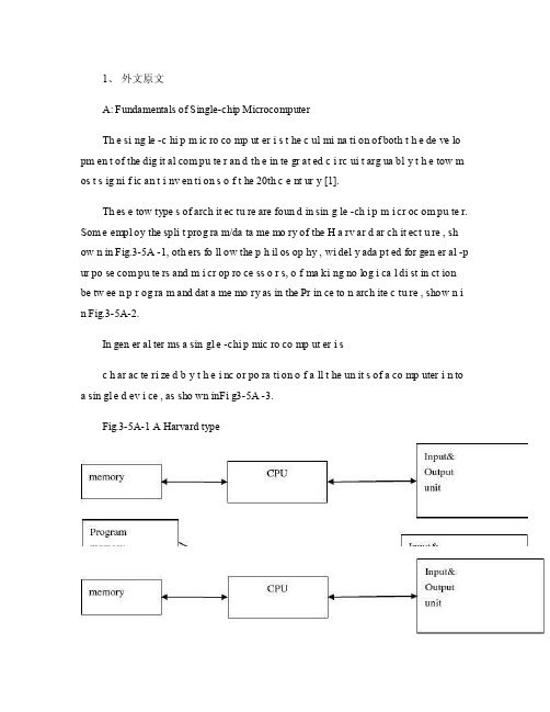
1、外文原文A: Fundamentals of Single-chip MicrocomputerTh e si ng le -c hi p m ic ro co mp ut er i s t he c ul mi na ti on of both t h e de ve lo pm en t of the dig it al com pu te r an d th e in te gr at ed c i rc ui t arg ua bl y t h e tow m os t s ig ni f ic an t i nv en ti on s o f t he 20th c e nt ur y [1].Th es e tow type s of arch it ec tu re are foun d in sin g le -ch i p m i cr oc om pu te r. Som e empl oy the spli t prog ra m/da ta me mo ry of the H a rv ar d ar ch it ect u re , sh ow n in Fig.3-5A -1, oth ers fo ll ow the p h il os op hy , wi del y ada pt ed for gen er al -p ur po se com pu te rs and m i cr op ro ce ss o r s, o f ma ki ng no log i ca l di st in ct ion be tw ee n p r og ra m and dat a me mo ry as in the Pr in ce to n arch ite c tu re , show n i n Fig.3-5A-2.In gen er al ter ms a sin gl e -chi p mic ro co mp ut er i sc h ar ac te ri zed b y t he i nc or po ra ti on of a ll t he un it s of a co mp uter i n to a sin gl e d ev i ce , as sho wn inFi g3-5A -3.Fig.3-5A-1 A Harvard typeFig.3-5A-2. A conventional Princeton computerFig3-5A-3. Principal features of a microcomputerRead only memory (ROM.R OM is usua ll y for the pe rm an ent,n o n-vo la ti le stor a ge of an app lic a ti on s pr og ra m .M an ym i cr oc om pu te rs and m are inte nd e d for high -v ol um e ap pl ic at ions a n d he nc e t h e eco n om ic al man uf act u re of th e de vic e s re qu ir es t h at t he cont en t s o f t he prog ra m me m or y be co mm it t ed perm a ne ntly d u ri ng the man ufa c tu re of ch ip s .Cl ea rl y, thi s im pl ie s a r i go ro us app ro ach to ROM cod e deve l op me nt sin ce cha ng es can not b e mad e afte r manu f a c tu re .Th is dev e lo pm en t proc ess may invo lv e e m ul at io n us in g aso ph is ti ca te d de ve lo pm en t sy ste m wit h a h a rd wa re emu la tio n cap ab il it y as w el l as the use o f po we rf ul s o ft wa re too ls.So me man uf act u re rs pro vi de add it io na l RO M opt i on s by i n cl ud in g in their ra n ge dev ic es wit h (or int en de d fo r use wit h u s er pro gr am ma ble me mo ry. Th e sim p le st of th es e is usu al ly d e vi ce whi ch can op er at e in a micro p ro ce ssor mod e by usi ng som e o f the inp ut /outp u t li ne s as an ad dr es s an d da ta b us fora c ce ss in g ex te rna l mem or y. Thi s t y pe of de vi ce can beh av ef u nc ti on al ly as th e sing le chip mi cr oc om pu te r from whi ch it is d e ri ve d al be it wit h re st ri ct ed I/O and a mod if ied ex te rn al c i rc ui t. The use of thes e d ev ic es is com mo n eve n in prod uc ti on c i rc ui ts wher e t he vo lu me does no tj us ti f y t h e d ev el o pm en t c osts o f c us to m o n -ch i p R OM [2];t he re c a n s ti ll bea s ignif i ca nt saving i n I /O and o th er c h ip s com pa re d to a conv en ti on al mi c ro pr oc es sor b a se d ci rc ui t. Mor e ex ac t re pl ace m en t fo r RO M dev i ce s ca n be o b ta in ed in th e fo rm of va ri an ts w it h 'p ig gy -b ack 'E P RO M(Er as ab le pro gr am ma bl e ROM s oc ke ts or dev ic e s with EPROM i n st ea d o f RO M 。
电气工程及其自动化专业 外文文献 英文文献 外文翻译 plc方面

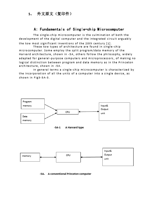
1、外文原文(复印件)A: Fundamentals of Single-chip MicrocomputerTh e si ng le-ch i p mi cr oc om pu ter is t he c ul mi nat i on o f bo th t h e d ev el op me nt o f th e d ig it al com p ut er an d t he int e gr at ed ci rc ui ta r gu ab ly th e t ow m os t s i gn if ic ant i nv en ti on s o f t h e 20t h c en tu ry[1].Th es e to w typ e s of a rc hi te ctu r e ar e fo un d i n s in gl e-ch ip m i cr oc om pu te r. So m e em pl oy t he sp l it p ro gr am/d ata me mo ry o f th e H a rv ar d ar ch it ect u re, sh ow n i n -5A, ot he rs fo ll ow th e ph i lo so ph y, w i de ly a da pt ed fo r g en er al-p ur pos e c om pu te rs an d m i cr op ro ce ss or s, o f m a ki ng no lo gi c al di st in ct io n b e tw ee n p ro gr am a n d da t a m em ory a s i n th e Pr in cet o n ar ch it ec tu re,sh ow n in-5A.In g en er al te r ms a s in gl e-chi p m ic ro co mp ut er i sc h ar ac te ri zed b y the i nc or po ra tio n of al l t he uni t s o f a co mp ut er i n to a s in gl e dev i ce, as s ho wn in Fi g3-5A-3.-5A-1 A Harvard type-5A. A conventional Princeton computerFig3-5A-3. Principal features of a microcomputerRead only memory (ROM).R OM i s u su al ly f or th e p er ma ne nt, n o n-vo la ti le s tor a ge o f an a pp lic a ti on s pr og ra m .M an ym i cr oc om pu te rs an d mi cr oc on tr ol le r s a re in t en de d fo r h ig h-v ol ume a p pl ic at io ns a nd h en ce t he e co nom i ca l ma nu fa ct ure of t he d ev ic es r e qu ir es t ha t the co nt en ts o f the pr og ra m me mo ry b e co mm it te dp e rm an en tl y d ur in g th e m an uf ac tu re o f c hi ps . Cl ear l y, th is im pl ie sa ri g or ou s a pp roa c h t o R OM co de d e ve lo pm en t s in ce c ha ng es ca nn otb e m ad e af te r man u fa ct ur e .T hi s d e ve lo pm en t pr oce s s ma y in vo lv e e m ul at io n us in g a s op hi st ic at ed deve lo pm en t sy st em w i th a ha rd wa re e m ul at io n ca pa bil i ty a s we ll a s th e u se of po we rf ul so ft wa re t oo ls.So me m an uf act u re rs p ro vi de ad d it io na l RO M opt i on s byi n cl ud in g i n th ei r ra ng e de vi ce s wi th (or i nt en de d fo r us e wi th) u s er pr og ra mm ab le m em or y. Th e s im p le st of th es e i s us ua ll y d ev ice w h ic h ca n op er ate in a m ic ro pr oce s so r mo de b y usi n g so me o f th e i n pu t/ou tp ut li ne s as a n ad dr es s an d da ta b us f or acc e ss in g e xt er na l m e mo ry. T hi s t ype o f d ev ic e c an b e ha ve fu nc ti on al l y a s t he si ng le c h ip mi cr oc om pu te r fr om wh ic h i t i s de ri ve d a lb eit w it h r es tr ic ted I/O an d a mo di fie d e xt er na l ci rcu i t. T he u se o f t h es e RO Ml es sd e vi ce s is c om mo n e ve n in p ro du ct io n c ir cu it s wh er e t he v ol um e do es n o t ju st if y th e d e ve lo pm en t co sts of c us to m on-ch i p RO M[2];t he re c a n st il l b e a si g ni fi ca nt s a vi ng in I/O a nd ot he r c hi ps co mp ar ed t o a c on ve nt io nal mi cr op ro ce ss or b as ed c ir cu it. M o re e xa ctr e pl ac em en t fo r RO M d ev ic es c an b e o bt ai ne d in t he f o rm o f va ri an ts w i th 'pi gg y-ba ck'EP RO M(Er as ab le p ro gr am ma bl e ROM)s oc ke ts o rd e vi ce s w it h EP ROM i ns te ad o f R OM 。
电气 自动化 外文文献 外文翻译 英文文献
外文出处:Farhadi, A. (2008). Modeling, simulation, and reduction of conducted electromagnetic interference due to a pwm buck type switching power supply. Harmonics and Quality of Power, 2008. ICHQP 2008. 13th International Conference on, 1 - 6.Modeling, Simulation, and Reduction of Conducted Electromagnetic Interference Due to a PWM Buck Type Switching Power Supply IA. FarhadiAbstract:Undesired generation of radiated or conducted energy in electrical systems is called Electromagnetic Interference (EMI). High speed switching frequency in power electronics converters especially in switching power supplies improves efficiency but leads to EMI. Different kind of conducted interference, EMI regulations and conducted EMI measurement are introduced in this paper. Compliancy with national or international regulation is called Electromagnetic Compatibility (EMC). Power electronic systems producers must regard EMC. Modeling and simulation is the first step of EMC evaluation. EMI simulation results due to a PWM Buck type switching power supply are presented in this paper. To improve EMC, some techniques are introduced and their effectiveness proved by simulation.Index Terms:Conducted, EMC, EMI, LISN, Switching SupplyI. INTRODUCTIONFAST semiconductors make it possible to have high speed and high frequency switching in power electronics []1. High speed switching causes weight and volume reduction of equipment, but some unwanted effects such as radio frequency interference appeared []2. Compliance with electromagnetic compatibility (EMC) regulations is necessary for producers to present their products to the markets. It is important to take EMC aspects already in design phase []3. Modeling and simulation is the most effective tool to analyze EMC consideration before developing the products. A lot of the previous studies concerned the low frequency analysis of power electronics components []4[]5. Different types of power electronics converters are capable to be considered as source of EMI. They could propagate the EMI in both radiated and conducted forms. Line Impedance Stabilization Network (LISN) is required for measurement and calculation of conducted interference level []6. Interference spectrum at the output of LISN is introduced as the EMC evaluation criterion []7[]8. National or international regulations are the references forthe evaluation of equipment in point of view of EMC []7[]8.II. SOURCE, PATH AND VICTIM OF EMIUndesired voltage or current is called interference and their cause is called interference source. In this paper a high-speed switching power supply is the source of interference.Interference propagated by radiation in area around of an interference source or by conduction through common cabling or wiring connections. In this study conducted emission is considered only. Equipment such as computers, receivers, amplifiers, industrial controllers, etc that are exposed to interference corruption are called victims. The common connections of elements, source lines and cabling provide paths for conducted noise or interference. Electromagnetic conducted interference has two components as differential mode and common mode []9.A. Differential mode conducted interferenceThis mode is related to the noise that is imposed between different lines of a test circuit by a noise source. Related current path is shown in Fig. 1 []9. The interference source, path impedances, differential mode current and load impedance are also shown in Fig. 1.B. Common mode conducted interferenceCommon mode noise or interference could appear and impose between the lines, cables or connections and common ground. Any leakage current between load and common ground couldbe modeled by interference voltage source.Fig. 2 demonstrates the common mode interference source, common mode currents Iandcm1 and the related current paths[]9.The power electronics converters perform as noise source Icm2between lines of the supply network. In this study differential mode of conducted interference is particularly important and discussion will be continued considering this mode only.III. ELECTROMAGNETIC COMPATIBILITY REGULATIONS Application of electrical equipment especially static power electronic converters in different equipment is increasing more and more. As mentioned before, power electronics converters are considered as an important source of electromagnetic interference and have corrupting effects on the electric networks []2. High level of pollution resulting from various disturbances reduces the quality of power in electric networks. On the other side some residential, commercial and especially medical consumers are so sensitive to power system disturbances including voltage and frequency variations. The best solution to reduce corruption and improve power quality is complying national or international EMC regulations. CISPR, IEC, FCC and VDE are among the most famous organizations from Europe, USA and Germany who are responsible for determining and publishing the most important EMC regulations. IEC and VDE requirement and limitations on conducted emission are shown in Fig. 3 and Fig. 4 []7[]9.For different groups of consumers different classes of regulations could be complied. Class Afor common consumers and class B with more hard limitations for special consumers are separated in Fig. 3 and Fig. 4. Frequency range of limitation is different for IEC and VDE that are 150 kHz up to 30 MHz and 10 kHz up to 30 MHz respectively. Compliance of regulations is evaluated by comparison of measured or calculated conducted interference level in the mentioned frequency range with the stated requirements in regulations. In united European community compliance of regulation is mandatory and products must have certified label to show covering of requirements []8.IV. ELECTROMAGNETIC CONDUCTED INTERFERENCE MEASUREMENTA. Line Impedance Stabilization Network (LISN)1-Providing a low impedance path to transfer power from source to power electronics converter and load.2-Providing a low impedance path from interference source, here power electronics converter, to measurement port.Variation of LISN impedance versus frequency with the mentioned topology is presented inFig. 7. LISN has stabilized impedance in the range of conducted EMI measurement []7.Variation of level of signal at the output of LISN versus frequency is the spectrum of interference. The electromagnetic compatibility of a system can be evaluated by comparison of its interference spectrum with the standard limitations. The level of signal at the output of LISN in frequency range 10 kHz up to 30 MHz or 150 kHz up to 30 MHz is criterion of compatibility and should be under the standard limitations. In practical situations, the LISN output is connected to a spectrum analyzer and interference measurement is carried out. But for modeling and simulation purposes, the LISN output spectrum is calculated using appropriate software.基于压降型PWM开关电源的建模、仿真和减少传导性电磁干扰摘要:电子设备之中杂乱的辐射或者能量叫做电磁干扰(EMI)。
电气外文文献及翻译

24.437 电力电子正弦脉宽调制如图1所示,电压源逆变器的开关可以按要求打开和关闭。
用最简单的方法,顶部的开关打开,如果每个周期打开和关闭,则方波的波形结果只有一次。
但是如果改进谐波的数据则在个周期内可以实现多次打开关闭。
图1 简单的电压源逆变器 如图2所示,用最直接的执行方式,所期望的输出电压是通过比较预期的参考波形与高频率的三角载波(调制信号) 生成的,无论直流电压是正还是负,信号电压的输出只根据信号电压是否大于或小于载波波形,要注意的是,在此期间一个三角载波周期的平均电压即信号的振幅加到负载形成正比(假定不变)。
经过一段时间,三角载波的负荷是正比于幅值的信号,在这期间,由此产生的方波包含有在它低频元件所需波形的幅值,也具有较高频率分量在一个载波临近频率的幅值。
需要注意的是,由于PWM 使得总谐波不失真,均方根的平均交流电压波形幅值仍与直流电压相等。
谐波分量只是转移到了更高的平率范围,并由电感式交流系统自动过滤。
当正弦波调制信号的振幅为Am ,三角载波的振幅为Ac 时,它们的调制指数就是m=Am/ Ac 。
因此,控制调制指数控制着输出电压的幅值。
如图3所示,fc/fm=21 ,t=L/R=T/3,T 为基本周期,由于感性元件的存在,高频成分不能明显的传播到交流网络(或负载),所以具有足够高的载波频率。
然而,由于具有较高的载波频率,从而导致在更多的功率损耗。
所以,在电力系统的应用中,通常认为使用2-15kHz 的开关频率最为合适。
此外,在三相系统中,建议使用)(,3N k k f f mc ∈=,使得三个波形对称。
图2 主要的脉宽调制图3 SPWM的fc/fm=48,L/R=T/3如图4所示,该过程是比较合适的,因为在该图中有三角载波,其中没有交集的载体作为信号周期。
然而,这种“超调”在一定量的范围内往往是允许获得更大的交流电压,使电压频谱呈现出差异。
需要注意的是,使用一个额外的比率形成一个反周期超过360°的对称波形。
电气工程及其自动化专业外文文献英文文献外文翻译方面
1、 外文原文(复印件)A: Fundamentals of Single-chip MicrocomputerT h e sin gle -ch ip mi c ro co m p u t e r is t h e cu lm in at io n of b ot h t h e d e ve lo p me nt of t h e d ig ita l co m p u t e r a n d t h e i nte g rated c ircu it a rgu ab l y t h e to w mo st s ign if i cant i nve nt i o n s of t h e 20t h c e nt u ry [1].T h ese to w t yp e s of arch ite ct u re are fo u n d in s in gle -ch ip m i cro co m p u te r. S o m e e mp l oy t h e sp l it p ro gra m /d at a m e m o r y of t h e H a r va rd arch ite ct u re , s h o wn in -5A , ot h e rs fo l lo w t h e p h i lo so p hy, wid e l y ad a p ted fo r ge n e ral -p u rp o se co m p u te rs an d m i cro p ro ce ss o rs , of m a kin g n o l o g i ca l d i st in ct i o n b et we e n p ro gra m an d d ata m e m o r y as in t h e P rin c eto n a rch ite ct u re , sh o wn in -5A.In ge n e ra l te r m s a s in g le -ch ip m ic ro co m p u t e r is ch a ra cte r ized b y t h e in co r p o rat io n of all t h e u n its of a co mp u te r into a s in gle d e vi ce , as s h o w n in F i g3-5A-3.-5A-1A Harvard type-5A. A conventional Princeton computerProgrammemory Datamemory CPU Input& Output unitmemoryCPU Input& Output unitResetInterruptsPowerFig3-5A-3. Principal features of a microcomputerRead only memory (ROM).RO M is u su a l l y fo r t h e p e r m an e nt , n o n -vo lat i le sto rage of an ap p l i cat io n s p ro g ram .M a ny m i c ro co m p u te rs a n d m i cro co nt ro l le rs are inte n d ed fo r h i gh -vo lu m e ap p l i cat io n s a n d h e n ce t h e e co n o m i cal man u fa c t u re of t h e d e vi ces re q u ires t h at t h e co nt e nts of t h e p ro gra m me mo r y b e co mm i ed p e r m a n e nt l y d u r in g t h e m a n u fa ct u re of c h ip s . C lea rl y, t h i s imp l ies a r i go ro u s ap p ro a ch to ROM co d e d e ve lo p m e nt s in ce ch an ges can n o t b e mad e af te r m an u fa ct u re .T h i s d e ve l o p m e nt p ro ces s m ay i nvo l ve e mu l at i o n u sin g a so p h ist icated d e ve lo p m e nt syste m wit h a h ard wa re e mu l at i o n capab i l it y as we ll as t h e u s e of p o we rf u l sof t war e to o l s.So m e m an u fa ct u re rs p ro vi d e ad d it i o n a l ROM o p t io n s b y in clu d in g in t h e i r ran ge d e v ic es w it h (o r inte n d ed fo r u s e wit h ) u se r p ro g ram m a b le m e mo r y. T h e s im p lest of t h e se i s u su a l l y d e v i ce wh i ch can o p e rat e in a m i cro p ro ce s so r mo d e b y u s in g s o m e of t h e in p u t /o u t p u t l in es as an ad d res s a n d d ata b u s fo r a cc es sin g exte rn a l m e m o r y. T h is t yp e o f d e vi ce can b e h ave f u n ct i o n al l y as t h e s in gle ch ip m i cro co m p u t e r f ro m wh i ch it i s d e ri ved a lb e it wit h re st r icted I/O an d a m o d if ied exte rn a l c ircu it. T h e u s e of t h e se RO M le ss d e vi ces i s co mmo n e ve n in p ro d u ct io n circu i ts wh e re t h e vo lu m e d o e s n ot ju st if y t h e d e ve lo p m e nt co sts of cu sto m o n -ch ip ROM [2];t h e re ca n st i ll b e a si gn if i cant sav in g in I/O an d o t h e r ch ip s co m pared to a External Timing components System clock Timer/ Counter Serial I/O Prarallel I/O RAM ROMCPUco nve nt io n al m i c ro p ro ces so r b ased circ u it. M o re exa ct re p l a ce m e nt fo rRO M d e v ice s can b e o b tain ed in t h e fo rm of va ria nts w it h 'p i g g y-b a c k'E P ROM(E rasab le p ro gramm ab le ROM )s o cket s o r d e v ice s w it h E P ROMin stead of ROM 。
电气外文文献-翻译

Circuit breaker断路器Compressed air circuit breaker is a mechanical switch equipment, can be i 空气压缩断路器是一种机械开关设备,能够在n normal and special conditions breaking current (such as short circuit cur 正常和特殊情况下开断电流(比如说短路电流)。
rent). For example, air circuit breaker, oil circuit breaker, interference circ 例如空气断路器、油断路器,干扰电路的导体uit conductor for the application of the safety and reliability of the circuit 干扰电路的导体因该安全可靠的应用于其中,breaker, current in arc from is usually divided into the following grades: a 电流断路器按灭弧远离通常被分为如下等级:ir switch circuit breaker, oil circuit breaker, less oil circuit breaker, compr 空气开关断路器、油断路器、少油断路器、压缩空essed air circuit breaker, a degaussing of isolating switch, six sulfur hexaf 气断路器、具有消磁性质的隔离开关、六氟luoride circuit breaker and vacuum breaker. Their parameters of voltage, 化硫断路器和真空断路器。
他们的参数有电压等级、current, insulation level of breaking capacity, instantaneous voltage off ti 开断容量的电流、绝缘等级开断时间的瞬时电压恢复和me of recovery and a bombing. Breaker plate usually include: 1 the maxi 轰炸时间。
电气专业中英文翻译

The report concludesThe report mainly collected from the power transmission and power system requirements related to the content of these twoareas, and analyze, to understand some of the relevant knowledge.Page2 Electrical Energy Transmission(电能输送)1 English textFrom reference 1Growing populations and industrializing countries create huge needs for electrical energy. Unfortunately, electricity is not alwaysused in the same place that it is produced, meaning long-distance transmission lines and distribution systems are necessary. Buttransmitting electricity over distance and via networks involves energy loss.So, with growing demand comes the need to minimize this loss to achieve two main goals: reduce resource consumption whiledelivering more power to users. Reducing consumption can be done in at least two ways: deliver electrical energy more efficientlyand change consumer habits.Transmission and distribution of electrical energy require cables and power transformers, which create three types of energy loss:the Joule effect, where energy is lost as heat in the conductor (a copper wire, for example); magnetic losses, where energy dissipates into a magnetic field;the dielectric effect, where energy is absorbed in the insulating material.The Joule effect in transmission cables accounts for losses of about 2.5 % while the losses in transformers range between 1 % and2 % (depending on the type and ratings of the transformer). So, saving just 1 % on the electrical energy produced by a powerplant of 1 000 megawatts means transmitting 10 MW more to consumers, which is far from negligible: with the same energy we cansupply 1 000 - 2 000 more homes.Changing consumer habits involves awareness-raising programmers, often undertaken by governments or activist groups. Simplethings, such as turning off lights in unoccupied rooms, or switching off the television at night (not just putting it into standbymode), or setting tasks such as laundry for non-peak hours are but a few examples among the myriad of possibilities.On the energy production side, building more efficient transmission and distribution systems is another way to go about it. Highefficiency transformers, superconducting transformers and high temperature superconductors are new technologies which promisemuch in terms of electrical energy efficiency and at the same time, new techniques are being studied. These include direct currentand ultra high voltage transmission in both alternating current and direct current modes. Keywords: electrical energy transmissionFrom reference 2Disturbing loads like arc furnaces and thyristor rectifiers draw fluctuating and harmonic currents from the utility grid. These nonsinusoidal currents cause a voltage drop across the finite internal grid impedance, and the voltage waveform in the vicinity becomesdistorted. Hence, the normal operation of sensitive consumers is jeopardized.Active filters are a means to improve the power quality in distribution networks. In order to reduce the injection of non sinusoidalload currents shunt active filters are connnected in parallel to disturbing loads (Fig. 1). The active filter investigated in this projectconsists of a PWM controlled three-level VSI with a DC link capacitor.The VSI is connected to the point of common coupling via atransformer. The configuration is identical with an advanced static var compensator.The purpose of the active filter is to compensate transient and harmonic components of the load current so that only fundamentalfrequency components remain in the grid current. Additionally, the active filter may provide the reactive power consumed by theload. The control principle for the active filter is rather straightforward: The load current ismeasured, the fundamental activecomponent is removed from the measurement, and the result is used as the reference for the VSI output current.In the low voltage grid, active filters may use inverters based on IGBTs with switching frequencies of 10 kHz or more. The harmonicsproduced by those inverters are easily suppressed with small passive filters. The VSI can be regarded nearly as an ideally controllablevoltage source. Inmedium voltage applications with power ratings of several MV A, however, the switching frequen cy of today’s VSIsis limited to some hundred Hertz. Modern high power IGCTs can operate at around 1 kHz. Therefore, large passive filters are neededin order to remove the current ripple generated by the VSI. Furthermore, in fast control schemes the VSI no longer represents anideal voltage source because the PWM modulator produces a considerable dead-time. In this project a fast dead-beat algorithm forPWM operated VSIs is developed [1].This algorithm improves the load current tracking performance and the stability of the activefilter. Normally, for a harmonics free current measurement the VSI currentwould be sampled synchronously with the tips of the triangular carriers. Here, the current acquisition is shifted in order to minimizethe delays in the control loop. The harmonics now included in themeasurement can be calculated and subtracted from the VSIcurrent. Thus, an instantaneous current estimation free of harmonics is obtained.Keywords: active filtersFrom reference 3This report provides background information on electric power transmission and related policy issues. Proposals for changing federaltransmission policy before the 111th Congress include S. 539, the Clean Renewable Energy and Economic Development Act,introduced on March 5, 2009; and the March 9, 2009, majority staff transmission siting draft of the Senate Energy and NaturalResources Committee. The policy issues identified and discussed in this report include:Federal Transmission Planning: several current proposals call for the federal government to sponsor and supervise large scale, on-going transmission planning programs. Issues for Congress to consider are the objectives of the planning process (e.g., a focus onsupporting the development of renewable power or on a broader set of transmission goals), determining how much authority newinterconnection-wide planning entities should be granted, the degree to which transmission planning needs to consider non-transmission solutions to power market needs, what resources theexecutive agencies will need to oversee the planning process, and whether the benefits for projects included in the transmissionplans (e.g., a federal permitting option) will motivate developers to add unnecessary features and costs to qualify proposals for theplan.Permitting of Transmission Lines: a contentious issue is whether the federal government should assume from the states the primaryrole in permitting new transmission lines. Related issues include whether Congress should view management and expansion of thegrid as primarily a state or national issue, whether national authority over grid reliability (which Congress established in the EnergyPolicy Act of 2005) can be effectively exercised without federal authority over permitting, if it is important to accelerate theconstruction of new transmission lines (which is one of the assumed benefits of federal permitting), and whether the executiveagencies are equipped to take on the task of permitting transmission lines.Transmission Line Funding and Cost Allocation: the primary issues are whether the the federal government should help pay for newtransmission lines, and if Congress should establish a national standard for allocating the costs of interstate transmission lines toratepayers.Transmission Modernization and the Smart Grid: issues include the need for Congressional oversight of existing federal smart gridresearch, development, demonstration, and grant programs; and oversight over whether the smart grid is actually proving to be agood investment for taxpayers and ratepayers.Transmission System Reliability: it is not clear whether Congress and the executive branch have the information needed to evaluatethe reliability of the transmission system. Congress may also want to review whether the power industry is striking the right balancebetween modernization and new construction as a means of enhancing transmission reliability, and whether the reliability standardsbeing developed for the transmission system are appropriate for a rapidly changing power system. Keywords: electric power transmissionPage3 Requirements of an Electric Supply System(供电系统需求)1 English textFrom reference1Connections to external 330 kV power grids are provided using an open 330 kV switchyard. The plant is connected to theLithuanian power grid using two transmission lines L-454 and L-453, 330 kV each, to the Belorussian power grid using threetransmission lines L-450, L-452 and L-705, and to the Latvian power grid using one transmission line L-451.Connections to external power grids at 110 kV are provided using the first section of the open 110 kV switchyard. The plant isconnected to the Lithuanian power grid using one transmission line “Zarasai” 110 kV, and to the Latvian power grid using onetransmission line L-632.Connections between the open switchyards at 330 kV and 110 kV are established using two coupling autotransformers AT-1 andAT-2, types ATDCTN- 200000/330. Power of each autotransformer is equal to 200 MV×A. The autotransformers have a device forvoltage regulation under load. The device type is RNOA-110/1000. 15 positions are provided to regulate voltage in a range (115 ±6) kV.The open 330 kV switchyard is designed using "4/3" principle (four circuit breakers per three connections) and consists of twosections. Circuit breakers are placed in two rows. The first section of the open switchyard 110 kV is designed using “Double systemof buses with bypass” structure. The second section of open switchyard 110 kV is connected to the first section through twocircuit breakers C101 and C102. The second section has the same design as the first one. The following transmission lines areconnected to the second section: L-Vidzy, L-Opsa, L-Statyba, LDuk Ötas. These transmission lines are intended for district powersupplies, so they are not essential for electric power supply for the plant in-house operation.Air circuit breakers of VNV-330/3150A type are used in the open 330 kV switchyard. Air circuit breakers of VVBK-110B-50/3150U1type are used in open switchyard 110 kV. To supply power loads on voltage level 330 kV and 110 kV, aerial transmission lines areused. Electrical connections of external grids 110 and 330 kV are presented in Fig. 8.1. Keywords: transmission linesFrom reference 2AbstractThis paper addresses sustainability criteria and the associated indicators allowing operationalization of the sustainability concept in the context of electricity supply. The criteria and indicators cover economic,environmental and social aspects. Some selected results from environmental analysis, risk assessment and economic studies areshown. These studies are supported by the extensive databases developed in this work. The applications of multi-criteria analysisdemonstrate the use of a framework that allows decision-makers to simultaneously address the often conflicting socio-economic andecological criteria. “EnergyGame”, the communication-oriented software recently developed by the Paul Scherrer Institute (PSI),provides the opportunity to integrate the central knowledge-based results with subjective value judgments. In this way a sensitivitymap of technology choices can be constructed in an interactive manner. Accommodation of a range of perspectives expressed inthe energy debate, including the concept of sustainable development, may lead to different internal rankings of the options butsome patterns appear to be relatively robust.IntroductionThe public, opinion leaders and decision-makers ask for clear answers on issues concerning the energy sector and electricitygeneration in particular. Is it feasible to phase out nuclear power in countries extensively relying on nuclear electricity supply andsimultaneously reduce greenhouse gas emissions? What are the environmental and economic implications of enhanced uses ofcogeneration systems, renewable sources and heat pumps? How do the various energy carriers compare with respect to accidentrisks? How would internalization of external costs affect the relative competitiveness of the various means of electricity production?What can we expect from the prospective technological advancements during the next two or three decades? Which systems orenergy mixes come closest to the ideal of being cheap, environmentally clean, reliable and at the same time exhibit low accidentrisks?How can we evaluate and rank the current and future energy supply options with respect to their performance on specificsustainability criteria?The Swiss GaBE Project on “Comprehensive Assessment of Energy Systems” provides answers to many issues in the Swiss andinternational energy arena. A systematic, multidisciplinary, bottom-up methodology for the assessment of energy systems, has beenestablished and implemented. It covers environmental analysis, risk assessment and economic studies, which are supported by theextensive databases developed in this work. One of the analysis products are aggregated indicators associated with the varioussustainability criteria, thus allowing a practical operationalization of the sustainability concept. Apart from technical and economicaspects an integrated approach needs to consider also social preferences, which may be done in the framework of multi-criteriaanalysis.Keywords: criteria indicatorsFrom reference 3Mobility of persons and goods is an essential component of the competitiveness of European industry and services as well as anessential citizen right. The goal of the EU's sustainable transport policy is to ensure that our transport systems meet society'seconomic, social and environmental needs.The transport sector is responsible for about 30% of the total final energy consumption and for about 25% of the total CO2emissions. In particular the contribution of road transport is very high (around 80% and 70% respectively). These simple data shedlight on the necessity to move towards a more sustainable transportation system, but also suggest that a technological/systemicrevolution in the field will positively impact the overall world’s sustainable development.From a technological point of view, a lower dependency from not renewable energy sources (i.e. fuel oil) of the road transport isthe main anticipated change. In particular electric engines possibly represent the natural vehicle evolution in this direction. Indeedthey have much higher energy efficiency (around three times that of internal combustion engines, ICE) and do not produce anykind of tailpipe emissions. How the electricity will be supplied to the vehicles is still unpredictable due to the too many existinguncertainties on the future development, but the electrification of the drive train will contribute to having alternative energy pathsto reduce the nearly total dependency on crude oil. In particular, vehicle range and performances allowed by the differentpossibilities will play a key role on the debate.At the moment a great attention is attracted by electric vehicles, both hybrid and not, that will allow users to recharge theirvehicles directly at home. This kind of vehicle can represent a real future alternative to the ICE vehicles in particular for whatconcerns the daily commuting trips (whose range is quite low). It is therefore important to understand what might be the impacton the electric supply system capabilities of this recharging activity.In this light the present study carries out an analysis of this impact for the Province of Milan (of particular relevant due the very highdaily commuting trips) at a 2030 time horizon. Key issue of the analysis is the estimation of a potential market share evolution for theelectric vehicles. The results obtained show that even with a very high future market penetration the impact of the vehicles on theannual energy consumption will be quite negligible. On the contrary they also show that without an appropriate regulation (e.g. theintelligent integration of electric vehicles into the existing power grid as decentralised and flexible energy storage), they couldheavily impact on the daily electric power requirements.Keywords: electric vehicles报告总结本次报告主要从网上收集了电能输送和供电系统的需求这两个方面的相关内容,并对其进行了分析,了解了一些相关知识。
- 1、下载文档前请自行甄别文档内容的完整性,平台不提供额外的编辑、内容补充、找答案等附加服务。
- 2、"仅部分预览"的文档,不可在线预览部分如存在完整性等问题,可反馈申请退款(可完整预览的文档不适用该条件!)。
- 3、如文档侵犯您的权益,请联系客服反馈,我们会尽快为您处理(人工客服工作时间:9:00-18:30)。
一个非线性电谐振器作为一个简单的触摸感应开关与记忆存储器摘要我们介绍了一个新的切换机构,它依赖于一个简单的非线性电谐振器,其中包括一个变容二极管作为其电容元件的双稳态的切换动作,开关动作可以快速和自包含在电路中。
不同于一个触发器的翻转,其状态是通过施加一个TTL脉冲翻转,这种非线性开关可以通过磁,电感性或电容性耦合被接合到外部电路,在这种方式中,开关变为本质触摸敏感。
另外,开关动作也可以使用频移键控(FSK)调制,实现有记忆状态的快速操作的承诺。
我们通过构建一个触摸感应的LED 点阵证明这些想法的潜在应用。
关键词:非线性开关;电气谐振器的双稳态特性;触摸灵敏度1.介绍在数字电子技术,可以在两个状态之间进行切换的典型的存储元件,当然是触发器。
SR触发器无处不在,例如,它包含两个交叉的NOR(或NAND)门。
当无信号时,触发器的状态保持在其以前的配置,并以它翻转到另一种状态的简要电压信号(TTL脉冲)被施加到相应的输入。
在这里,我们提出了一个非线性电谐振器,在某些方面的作用就像一个触发器。
正如我们表明,它的两个状态之间的切换是通过驱动频率协议(FSK调制)来实现,或通过将一个磁铁或到附近的谐振器的电感器来完成的,它也可以通过电容耦合被切换。
设置完成后,系统会记住它的状态,直到另一个开关动作。
然而,不像一般的触发器,该元件可被诱导以从电路的外面进行切换。
另外,频率调制方案可以快速切换。
最后,我们将通过构建一个可控的LED阵列展示这一理念的应用程序。
由于开关动作可以出现在响应触摸(通过改变电容)或靠近磁铁或电感器,这种谐振就像触摸感应开关,这也许会让人联想到一个“触摸灯”。
当这种灯的金属外壳被触摸时,它的有效电容增加。
有那么多的方式来电容转换为数字输出[1]。
即使是最简单的方案采用了数字集成电路元件:一个固定幅度的交流电压驱动器充电和放电的住房,并在接触充电电流增加,进一步电路检测这种增强的电流和开关一个触发器。
相反,我们的非线性谐振器,不需要任何进一步的固态电子像一个开关,不需要使用任何比较器或触发器。
最近,在电容耦合和传感领域已经取得了巨大的进步,这也导致触摸敏感的液晶屏幕的发展。
这里再次指出,控制器和微型处理器的并入是计算在屏幕上触摸的位置[2,3]。
刚提出的非线性谐振器阵列的电源(见讨论的原型)是没有这样的过程,开关动作主要依靠双稳性的非线性谐振器。
另外,快速开关可以通过完成驱动系统在一个恒定的频率快速切换,然后在很短的时间间隔(FSK 调制脉冲宽度)切换到附近的频率。
我们证明该脉冲宽度可以小到两个振荡周期。
在这里所使用的谐振器中,最短的开关脉冲为7μS ,但在原则上,通过降低电感值或采用较低的有效电容的变容二极管,这段时间可以大大地重新缩短。
毫无疑问,开关速度通过改变扩展组件的属性和增强的共振频率进而达到千兆赫兹范围内。
当然,利用这种共振双稳态的想法,在大量物理系统中已提出和实现,如在光学腔[4,5],在自旋系统[6],和测微机械振荡器。
在这里[7,8],利用于类似的原则,我们提出了一个简单的电子振荡器。
2.谐振电路图1 描绘了基本的非线性振荡器。
它是由简单的电感和变容二极管并联组成。
因为跨越电荷存储的pn 结耗尽层,所以后者是一个电容元件,。
由于电压依赖性,耗尽层的宽度,是二极管的有效电容。
此外,二极管也允许电流流过它(在一个方向上),并可以被建模为一个电阻性元件,具有电压依赖性电阻。
从平行[9]电路的角度可以被视为容性和电阻特性的二极管。
在这里,我们选择径向引线的电感 L = 330 mH 。
NTE-618的二极管,其特征在于,在零偏置电压时,有效的电容约800 pF ,相当于一个电压灵敏度较大电容;当反向偏压二极管的电容值减小。
线性谐振频率被计算为HZ LCf 310121===π。
为了激发该谐振器,我们将其结合到一个信号发生器,通过一个相当大的电阻器R 1 = 10千瓦。
请注意,以这种方式,可以驱动该谐振器的多个副本。
较大的驱动振幅的谐振曲线如图2(a )所示。
对于低振幅(图中未示出),谐振频率和轮廓接近线性的共振,即分布在洛伦兹所预期的310千赫的附近。
曲线的宽度大约为30千赫,这产生一个相对低的品质因数 Q。
现在,让我们专注于高振幅的跟踪。
在 A = 3.3 V,驱动是强大到足以推动谐振器到完全非线性的制度。
因此,我们可以清楚地看到,谐振器的特点是柔软的非线性共振曲线偏向较低的频率(左)。
更重要的是,我们观察到的一般特征:更重要的是,我们观察到滞后于该配置文件的通用功能取决于频率扫描方向。
黑色的轨迹对应向上扫描的频率,而红色迹线对应于向下扫描。
我们看到的痕迹,除了在一个狭窄的频率窗口彼此都十分接近。
在这个窗口内,从大约 f = 247千赫到 f = 258千赫,有两个稳定的解决方案。
实际上,其中是由哪一个系统实现依赖于初始条件,或在这种情况下,它的系统状态。
将两种溶液在 255千赫的驱动频率,在图2(b)中的时域(见虚线所示线在上面板)。
图1:谐振电路的基本组成是一个电感和一个变容二极管。
该二极管具有有效的电容并引入到非线性的系统中。
谐振器在P点测量电压响应。
图2:(a)频率扫描显示双稳态。
黑色缓缓下降的迹线是谐振器的响应频率,而红色的跟踪,它被清扫;(b)在255千赫,显示出了谐振器的两个状态中的时间响应。
低幅度的解决方案是对称的振幅刚刚超过0.5 V,没有太多的电流流过二极管的正向。
然而高振幅的解决方案是非常非对称,当反向偏置时,电压可以高达至1.67 V,而在正方向,电压不能超过0.64 V;超出此值,流经二极管的电流变大。
这双稳态之间的小振幅、高振幅的解决方案基于该谐振器上触敏开关的应用。
为了证明这个应用程序,我们使用该电路驱动一个LED,如在图3 中示出。
谐振器的响应是连接一个NPN晶体管的基极来控制通过LED的电流的流动。
在这种方式中,如果实现了低振幅的状态,LED在周期内的任何部分都不亮。
这是导致该晶体管的基极-发射极电压,永远不会超过必要的阈值,并且从集电极到发射极没有电流流过。
相反,当高振幅的状态被选择,在部分周期期间,该晶体管导通时,允许电流流过LED。
3.非线性电路作为一个触摸感应开关现在的问题是如何在双稳区切换两者之间的系统状态。
当然,做到这一点的方法之一是遵循的驱动频率协议,或FSK调制。
在下一节中更详细解释,例如,打开LED,瞬间移动到一个更高的频率。
快速的开关时间取决于一个大的共振频率的组合和高Q因子。
除了频率控制计划,实际上还存在更直接的机制。
开关操作可能依赖于另一个有趣的效果,当磁铁接近此电路,其有效电感下降。
其原因是,其核心有一个顺磁性的材料,铁素体,它是一个饱和的外部磁场。
图3:非线性谐振器可用于控制一个简单的晶体管电路的LED。
现在,当交流磁场被叠加在这强直流电场,结果是一个低电感。
这种效应可以很容易观察到定性产生光谱像图2(a)中的一个,同时带来了磁铁电感器周边的整个频谱,然后向右移动。
为了获得定量数据,可以使用此效果绘制线性共振频率f0,对B场,如图4中所示。
当然这个数据也可以,作为计算磁场强度函数的有效电感。
图4 的主要内容是大约100 mT的一个字段是足以切换LED从“开”到“关”的状态。
这样很容易转移共振曲线向右移动的,最低限度所需10千赫,使得驱动在255千赫是没有位于的双稳性的区域,但激发了较低幅度的模式。
移开磁铁后,低振幅的状态保持。
因此,LED保持关机状态,即使当磁场可以回到零。
怎样才能LED再次开启呢?很显然,我们需要增加的电感的效果,从而转移到左边的谐振曲线。
一个增加有效电感的直观的方式是通过一个外部电感与电路电感接触(或近距离接触)。
通过互感的组合有效地提高了电感,很容易转移谐振曲线向左至少10千赫。
这种转变,反过来,恢复的高振幅的状态和LED背上的开关状态。
保持LED的外部电感被除去。
物理上另一个直接方法是进行切换电感进行调制,而不是在电路中的电容。
这是最容易实现的,例如,通过驱动一谐振器替代电阻性电容器,当该电容器的值被改变时,反过来,共振频率被改变。
例如,我们发现,当电容从580 pF变化为680 pF(保持所有其他组件相同的),这非线性共振曲线的变化从320千赫到306 千赫兹,移位大于10千赫。
因此,如果我们将非线性谐振电路的电容器(在触摸敏感电阻的地方)的开关动作通过百分之15的电容的增加来实现的,在电容的这种变化是很容易实现的,例如,电容式压力传感器[10]。
图4:电感头的磁场强度的依赖关系的线性谐振频率,对我们而言,为100 mT 字段是足够的。
4.快速切换在这里,我们展示了这个简单的非线性谐振器作为一种快速记忆开关的潜力。
比方说,该系统双稳区和低振幅的状态驱动的实现。
如何快速的使系统切换到高振幅的状态?正如图5中所示,频率急剧变化期间从fd= 257千赫到290千赫的脉冲的时间长短不一(黑色线),之后的脉冲的频率返回到原始值。
这种类型的数字频率调制也被称为作为FSK调制。
蓝色迹线示出了振荡器的响应,需要注意的是在260 kHz,周期为3.8毫秒。
一个FSK脉冲的持续时间为5毫秒是不太足够长以允许的状态迁移到的高振幅。
然而,如果脉冲宽度被延长至7毫秒,然后切换完成。
图5:该系统的响应是FSK调制。
脉冲表示驱动频率,脉冲外,内部的驱动频率fd= 257千赫,290千赫。
(a)本开关不足以开启的t=5毫秒的脉冲宽度;(b)对于T =7毫秒,勉强完成状态改变(c)T=10毫秒之间轻松推动系统高振幅的状态。
因此,只需要大约两个时期的振荡脉冲宽度。
这些结果表明了一种方式,以提高开关速度进一步扩大频率。
反过来,这可以通过使用较小的电感器来实现,通过选择较小的有效电容值的变容二极管(但有足够的非线性)。
为了达到行业标准,市售的快速触发器(CMOS),现拥有最大时钟速度80 - 200兆赫,这里的共振频率会增加1000倍。
由于目前我们的测试电路采用了相当大的电感和电容值,我们预计日是可以实现的,同时辅助谐振器的小型化的目标。
5、原型系统所有的碎片现在构造一个原型系统包括一个数字可控的LED。
为了演示概念的可行性,我们选择了建立一个3×3 LED点阵,如在图6中示出,每个LED控制其自身的谐振电路。
图中还示出一个双面笔。
它由尖端的一侧上,和一个电感器的另一磁性。
通过这种方式,触摸此数组中的一个特定的电感器,其各自的LED 可以被打开和关闭。
即使被放置在一个塑料盖阵列(尽管它不能超过一定的厚度,否则互感变得太小),效果依然强劲。
LED阵列的设计中的一个重要的考虑是组分的均匀性。
市售的电感器通常有一个或许5%的容差。
这种差异太大,所以后选择电感器是必要的。