SMC减压阀说明书
SMC系列产品使用说明书
5.3对于1-PC和牙嵌式驱动空心轴的电动装置其安装方法是:起吊电动装置使1-PC空心轴孔与阀杆和键配合装入,牙嵌驱式空心轴上的牙嵌与阀门上阀杆螺母的牙嵌对准。用螺栓将电动装置与阀门紧固可靠。
4.1专用电动机:适合阀门的载荷特性和使用工况,型号YLT。
4.2减速机构:用于传递和增大电动机的动力。每个机座产品均有3~5种速比的蜗轮副和若干电机齿轮与蜗杆轴齿轮传动比的齿轮副,因而可获得较大的输出转速范围。
4.3驱动空心轴:它是电动装置的动力输出部件,有2-PC、1-PC、牙嵌式三种型式,结构可见(图10)~(图12)
2.基本技术参数
产品符合JB/T8528-1997《普通型阀门电动装置技术条件》
2.1动力电源:380V、50Hz三相正弦交流电(根据用户要求,某些规格可提供使用单相220V电源的电动机)。
2.2外壳防护等级:SMC-04、03 IP67
SMC-00~5 IP65
2.3使用环境温度:-20℃~40℃;-20℃~60℃(根据用户订货要求)
G·L·SW各列转体上触点的相对位置可任意布置,即同一列上的触点可以全部为“OFF”型式或为“OFF”“ON”两种型式。(最常用的是“OFF”“ON”的布置型式)。
G·L·SW中间的两列转体触点开关可做为阀门某两个中间位置的信号输出,也可将其调整到与两边的转体同步动作。
(图17)为典型控制原理时触点开关的布置型式。
电气接线程序及注意事项:
7.1确认电源电压与电动机使用电压相同。
SMC说明书
-2No.PS##-OMM0007-B
tion
The product is provided for use in manufacturing industries. The product herein described is basically provided for peaceful use in manufacturing industries. If considering using the product in other industries, consult SMC beforehand and exchange specifications or a contract if necessary. If anything is unclear, contact your nearest sales branch.
-1No.PS##-OMM0007-B
Safety Instructions
These safety instructions are intended to prevent hazardous situations and/or equipment damage. These instructions indicate the level of potential hazard with the labels of "Caution", "Warning" or "Danger". They are all important notes for safety and must be followed in addition to International standards (ISO/IEC) ∗1) and other safety regulations.
减压阀使用说明

减压阀使用说明
(膜片阀系列)
一、准备工作
1.收到产品后,查看产品包装是否完好;打开包装,查看阀体外观、压力表是否完好。
包装损坏时请拒绝签收,并联系BVF。
2.装配阀门都有进(INLET)出(OUTLET)口标识,按标识接入管路即可。
在装阀门前,设备管路需要吹扫,接钢瓶则无需吹扫。
二、调压
1. 调压前,手柄必须在0位,即手柄逆时针旋转到头。
2. 通气,这时进口有高压,顺时针旋转手柄调压,调到需要的压力即可。
进口接钢瓶时,由于钢瓶压力随着使用会降低,这时阀门出口压力升高(手柄不动时),这是正常现象,这时可适当旋转手柄调节到需要压力即可。
手柄上有标识:INCREASE出口压力增大和DECREASE出口压力减小
3. 关闭时应先关闭阀前压力,然后关闭减压阀,手柄归0位。
这时即可泄压。
三、注意事项
1.连接阀门的管路、接头必须可靠,并满足使用压力与温度的要求,连接处要采取密封处理,不可泄漏。
2.阀门手柄不在0位时,不可通压;进口压力等于或低于设定压力(最大可调出口压力)时,不可调压,以免损坏膜片和主弹簧。
SMC VFR4000中文使用说明书
请在仔细阅读理解内容的基础上安装使用该产 品。另外请妥善保管此说明书以便随时使用。 ③涂装时 产品上印刷或粘贴的警告及规格参数,请不要消 除、剥落,涂抹文字。另外,对树脂部分进行涂 装时,因为溶剂的关系可能会产生不良的影响, 请与本公司确认。
配管
注意
①配管前的处理 配管前,充分吹净或洗净管内的切屑末,切屑油或 灰尘等。
②密封带的缠绕方法 配管和管接头是螺纹连接的场合,请不要将配管螺 纹的细末和密封带的碎片混入阀体的内部。使用密 封带时,螺纹前端应留出 2 个螺距不卷绕密封带。 密封带的卷绕方法如图所示。
缠绕方向
配管
④关于接头的连接
管接头拧入电磁阀时,请按下述力矩拧紧。
连接螺纹
拧紧力矩 N・m
Rc3/8
22~24
Rc1/2
压缩空气一旦使用失误,是很危险的。气动设备的组装、操作和维护等,应由有足够知识和 经验的人进行。 3.在确认安全之前,绝对不许使用气动设备或从设备上拆卸元件。 1)在气动设备点检和维修之前,必须确认被驱动物体已进行了防止落下或暴走的处置。 2)在确认已进行了上述安全处置,切断对该设备供给的电源和气源,排放掉气动系统内残存的压
P9 P10 P11 P12 P13 P13 P14 P14 P15 P16
mmoorree::nn
VFR4000 Series
! 安全上的注意
这里所指注意事项,记载了产品应如何安全正确的使用,以防止对您及他人造成损伤。根据其潜在 的危险程度,将有关注意事项分成“注意”,“警告”和“危险”三种标志。 不论哪种标志,都是与 安全相关的重要内容,故在遵守 ISO 4414※1)、JIS B 8370※2)以及其他安全规则的同时,也必须遵守 此项内容。
SMC减压阀
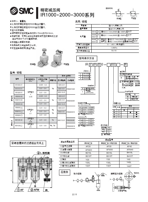
!"IR1000 2000 3000常泄口: 最大9.5l /min(ANR)在1.0MPa 压力下排气口: 最大2 l /min(ANR)在最高设定压力下最大3.5 l /min(ANR)在1.0MPa 压力下最大3.1 l /min(ANR)在1.0MPa 压力下标准型气控型应用例安装在模块式过滤组合元件上灵敏度重复精度耗气量环境及流体温度在0.2%满度以内在±0.5%满度以内-5 ~ +60℃(未冻结时)IR10□0IR20□0IR2120IR30□0IR3120最高使用压力压力表连接口径1.0MPa Rc1/8共同/规格无记号注)N 注)F NPT G Rc 注) 准标准品。
标准型气控型●体积小,重量轻。
● 比传统的精密减压阀IR200输出流量大。
● 比传统的精密减压阀IR200溢流流量大。
● 压力设定精确。
● 调节螺钉的齿间距由传统的0.75mm 改为0.5mm 。
● 安装方便,可用托架独立安装或与现在的模块式过滤组合元件AF 及AFM 直接安装。
●标准型也带面板安装。
● 先导排气口与主排气口分开。
● 可在洁净房使用(特注产品)。
!"#IR20□0-02!"IRV 000真空压力(负压)现可以任意调节!■灵敏度高■重复精度高■调节范围宽用途例工件的吸着真空测试检查装置真空泵电磁阀过滤器吸盘工件电磁阀真空泵真空罐过滤器吸盘工件真空泵电磁阀工件过滤器电磁阀压力转换器真空泵真空罐差压感应器电磁阀过滤器单一压力的情况不同压力的情况真空罐IRV IRVIRVIRV工件型号表示方法记号01020304口径1/81/43/81/2适合系列IRV1000IRV 23000IRV3000压力表接管口径接管口径大气接管口径压力表接管口径(吸盘侧)(真空泵侧)接管口径大气2-Rc1/82-Rc1/82-1/4·3/8,1/2Rc1/22-1/82-1/4。
SMC 5个口径液压阀门 VK3000 说明书

Instruction Manual 5 Port Solenoid Valve Series VK3000The intended use of this product is to control the movement of anactuator.These safety instructions are intended to prevent hazardous situationsand/or equipment damage. These instructions indicate the level ofpotential hazard with the labels of “Caution,” “Warning” or “Danger.”They are all important notes for safety and must be followed in additionto International Standards (ISO/IEC) *1), and other safety regulations.*1) ISO 4414: Pneumatic fluid power - General rules relating to systems.ISO 4413: Hydraulic fluid power - General rules relating to systems.IEC 60204-1: Safety of machinery - Electrical equipment of machines.(Part 1: General requirements)ISO 10218-1: Robots and robotic devices - Safety requirements forindustrial robots - Part 1: Robots.•Refer to product catalogue, Operation Manual and HandlingPrecautions for SMC Products for additional information.• Keep this manual in a safe place for future reference.Warning•Always ensure compliance with relevant safety laws andstandards.•All work must be carried out in a safe manner by a qualified person incompliance with applicable national regulations.•If this equipment is used in a manner not specified by themanufacturer, the protection provided by the equipment may beimpaired.Caution•The product is provided for use in manufacturing industries only. Donot use in residential premises.2 SpecificationsNote 1) Based on dynamic performance test, JIS B 8419: 2010. (Coil temperature:20°C, at rated voltage, without surge suppressor).Note 2) Impact resistance: No malfunction occurred when it is tested with a droptester in the axial direction and at the right angles to the main valve andarmature in both energized and de-energized states every once for eachcondition. (Values quoted are for a new valve).Vibration resistance: No malfunction occurred in a one-sweep test between45 and 2000 Hz. Test was performed at both energized states in the axialdirection and at the right angles to the main valve and armature. (Valuesquoted are for a new valve).Note) At the rated voltage.2.3 Low wattage VK31#0Y type•Specifications different from standard are as follows:2.4 Light indicationFigure 1.2.5 Special productsWarningSpecial products (-X) might have specifications different from thoseshown in this section. Contact SMC for specific drawings.3 Installation3.1 InstallationWarning•Do not install the product unless the safety instructions have been readand understood.•When mounting a valve or spacer on the manifold base or sub-plate,etc., the mounting orientation is already decided. If mounted in a wrongdirection, the equipment to be connected may result in malfunction(see Figure 10 under section 3.14). VK300 series valves can bemounted on the manifold base VV5K3 of VK3000 series. Refer tocatalogue for more details.3.2 EnvironmentWarning•Do not use in an environment where corrosive gases, chemicals, saltwater or steam are present.•Do not use in an explosive atmosphere.•Do not expose to direct sunlight. Use a suitable protective cover.•Do not install in a location subject to vibration or impact in excess ofthe product’s specificati ons.•Do not mount in a location exposed to radiant heat that would result intemperatures in excess of the product’s specifications.•When the solenoid valve is mounted in a control panel or it is energizedfor a long time, make sure that the ambient temperature is within thespecification of the valve.•If using in an atmosphere where there is possible contact with waterdroplets, oil, weld spatter, etc., take suitable preventive measures.3.3 PipingCaution•Before connecting piping make sure to clean up chips, cutting oil, dustetc.•When installing piping or fittings, ensure sealant material does notenter inside the port. When using seal tape, leave 1 thread exposedon the end of the pipe/fitting.3.4 LubricationCaution•SMC products have been lubricated for life at manufacture, and do notrequire lubrication in service.•If a lubricant is used in the system, refer to catalogue for details.3.5 Air supplyWarning•Use clean air. If the compressed air supply includes chemicals,synthetic materials (including organic solvents), salinity, corrosive gasetc., it can lead to damage or malfunction.Caution•Install an air filter upstream of the valve. Select an air filter with afiltration size of 5 μm or smaller.3.6 Effect of back pressure when using a manifoldWarning•Use caution when valves are used on a manifold, because an actuatormay malfunction or unexpected movement may occur due to backpressure.•For a single acting cylinder, take appropriate measures to preventmalfunction by using it with an individual exhaust manifold.3.7 Light/surge voltage suppressorDIN Terminal (D)NoneCautionIn the case of valves without surge suppressor, the machine designershall add suppression as close as possible to the valve.Figure 5.3.8 Residual voltage of the surge voltage suppressorCaution•If a Zener diode or varistor voltage suppressor is used, the suppressorarrests the back EMF voltage from the coil to a level in proportion tothe rated voltage.•Ensure the transient voltage is within the specification of the hostcontroller.•Contact SMC for the Zener diode or varistor residual voltage.•In the case of a diode, the residual voltage is approximately 1 V.•Valve response time is dependent on surge suppression methodselected.3.9 Countermeasure for surge voltageCaution•At times of sudden interruption of the power supply, the energy storedin a large inductive device may cause non-polar type valves in a de-energized state to switch.•When installing a breaker circuit to isolate the power, consider a valvewith polarity (with polarity protection diode), or install a surgeabsorption diode across the output of the breaker.3.10 How to wire DIN terminal wiringCaution•The DIN terminal wiring connection can achieve IP65 (enclosure)rating on the connector and cable entry only when using a heavy dutycable with O.D. of Ø3.5 mm to Ø7 mm, (0.5 mm2 2 core and 3 corewires equivalent to JIS C 3306).•Cable must exit perpendicularly and not at an angle.•Tighten the ground nut and set screw within the specified torque range•IP enclosure rating for all other valve parts remain as per Table 1.•Refer to catalogue for additional details.ORIGINAL INSTRUCTIONSBody ported Base mountedVaristorCoilCoil1Varistor1(+)(+)12Diode2 (-)DiodeRed (+)Black (-) D iodeVaristorCoil1Varistor122Red (+)Black (-)Surge voltagesuppressorMarkingIndicator light(Built-inconnector)Surge voltagesuppressor(Built-in terminal)MarkingAC, 12 VDC orless for DCFor 24 V or moreLight (built-in connector)DIN type only12NeonbulbVaristor2Figure 6.Figure 7. DIN type C3.10.1 Circuit with indicator light for DIN terminalFigure 8.3.10.2 Changing cable entry directionCaution• After separating terminal block and housing, the cable entry direction can be changed by attaching the housing in the desired direction (4 directions in 90 degree increments).• In the case of valve with indicator light, avoid damaging the light with lead wire . 3.11 Extended periods of continuous energizationWarningIf a valve will be continuously energized for an extended period of time, the temperature of the valve will increase due to the heat generated by the coil assembly. This will likely adversely affect the performance of the valve and any nearby peripheral equipment. Therefore, if the valve is to be energized for periods of longer than 30 minutes at a time or if during the hours of operation the energized period per day is longer than the de-energized period, we advise using a valve with continuous duty such as SY series (with ≤0.4 W power or with power saving circuit). 3.12 Manual overrideWarningRegardless of an electric signal for the valve, the manual override is used for switching the main valve. Connected actuator is started by manual operation. Only use the manual override after confirming that there is no danger.3.13 Use as a 3-port valveCautionThe VK3000 series can be used as 3 port valve, as a N.C. or N.O. type, by plugging either 4(A) or 2(B) cylinder Port. Make sure not to plug the exhaust ports 5(R1) and 3(R2).Table 5.3.14 Mounting and removal of valvesCaution• Ensure gaskets are in good condition, not deformed and are dust and debris free.• When mounting valves ensure gaskets are present, aligned and securely in place.• Tighten the valve mounting screw and bracket screw (if required) to the appropriate tightening torque of 0.6 N·m.• Refer catalogue for details of mounting and removal of valves from manifold.Figure 9.4 How to OrderRefer to catalogue for ‘How to Order’ or product drawing for special products.5 Outline DimensionsRefer to catalogue for outline dimensions.6.1 General maintenanceCaution• Not following proper maintenance procedures could cause the product to malfunction and lead to equipment damage.• If handled improperly, compressed air can be dangerous.• Maintenance of pneumatic systems should be performed only by qualified personnel.• Before performing maintenance, turn off the power supply and be sure to cut off the supply pressure. Confirm that the air is released to atmosphere.• After installation and maintenance, apply operating pressure and power to the equipment and perform appropriate functional and leakage tests to make sure the equipment is installed correctly.• If any electrical connections are disturbed during maintenance, ensure they are reconnected correctly and safety checks are carried out as required to ensure continued compliance with applicable national regulations.• Do not make any modification to the product.• Do not disassemble the product, unless required by installation or maintenance instructions.7 Limitations of Use7.1 Limited warranty and disclaimer/compliance requirementsRefer to Handling Precautions for SMC Products. 7.2 Holding of pressure (including vacuum)WarningSince valves are subject to air leakage, they cannot be used for applications such as holding pressure (including vacuum) in a system. 7.3 Cannot be used as an emergency shut-off valveWarningThis product is not designed for safety applications such as an emergency shut-off valve. If the valves are used in this type of system, other reliable safety assurance measures should be adopted.7.4 Breathing holeCautionFigure 10.There is a breathing hole on the bottom surface of the valve. Please note that liquid may enter or block the breathing hole, which may cause malfunction.7.5 Leakage voltageCautionEnsure that any leakage voltage caused by the leakage current when the switching element is OFF causes ≤2% (for DC coils) or ≤20% (for AC coils) of rated voltage across the valve. 7.6 Low temperature operationCautionUnless otherwise indicated in the specifications for each valve, operation is possible to -10˚C, but appropriate measures should be taken to avoid solidification or freezing of drainage and moisture, etc.8 Product DisposalThis product shall not be disposed of as municipal waste. Check your local regulations and guidelines to dispose this product correctly, in order to reduce the impact on human health and the environment.9 ContactsRefer to or www.smc.eu for your local distributor/importer.URL : https:// (Global) https:// www.smc.eu (Europe) SMC Corporation, 4-14-1, Sotokanda, Chiyoda-ku, Tokyo 101-0021, JapanSpecifications are subject to change without prior notice from the manufacturer. © 2021 SMC Corporation All Rights Reserved. Template DKP50047-F-085MCompatible cable: of Ø3.5 mm to Ø7mmGround nutTightening torque WasherGrommet (Rubber) (Voltage symbol) Terminal screw (3 positions)Tightening torque 0.2 N·m to 0.25 N·mHolding screw Tightening torque 0.3 N·m to 0.4 N·m Housing (Position for light mounting) Terminal block Slot area(+)(-)1.65 N·m to2.5 N·mN·m GroundR NLLEDR RLEDD NL: Neon light R: ResistorLED: Light emitting diodeR: ResistorD: Protective diodeLED: Light emitting diode R: ResistorBleed holeP P P PRRP R RRPP P PPP P P RRP R RR RRR R RP R PRRRRRRPPPPPPR RR R。
SMC减压阀工作原理和型号介绍
SMC减压阀工作原理和型号介绍
一.SMC减压阀工作原理
1.顺时针调节手轮,调压弹簧被压缩,推动膜片组件下移,通过阀杆,打开阀芯,则入口气压力
经阀芯节流降压,压力输出;
2.出口压力气体经反馈管进入膜片下腔,在膜片产生一个向上的推力。
当此推力与调压弹簧力平
衡时,出口压力便稳定一定在值。
二.SMC减压阀特点
1.体积小,重量轻。
2.比传统的精密减压阀IR200输出流量大。
3. 比传统的精密减压阀IR200溢流流量大。
4.压力设定精确。
5.调节螺钉的齿间距由传统的0.75mm改为0.5mm。
6. 安装方便,可用托架独立安装或与现在的模块式过滤组合元件AF及AFM直接安装。
7.标准型也带面板安装。
8.先导排气口与主排气口分开。
9. 可在洁净房使用(特注产品)。
三.我们一起来看看ARJ1020F微型减压阀
特长:小型、轻量(16g) ;低开启压力0.02MPa;标准规格带逆流功能;集装板(可选项);
型号有:
ARJ310-01
ARJ310-01-1
ARJ310F-01-04
ARJ310F-01-06
ARJ310F-01BG041
10ARJ210M5BG241
ARJ1020F-M5-04
ARJ1020F-M5-041
ARJ1020F-M5-06
ARJ1020F-M5-061
ARJ210-M5
ARJ210-M5-1
ARJ210-M5-S
ARJ210-M5-X215
ARJM10-10 ARJM10-4。
减压阀说明书
使用说明书减压阀宏源自动化仪表有限公司概述减压阀(Reducing valve)是采用控制阀体内的启闭件的开度来调节介质的流量,将介质的压力降低,同时借助阀后压力的作用调节启闭件的开度,使阀后压力保持在一定范围内,在进口压力不断变化的情况下,保持出口压力在设定的范围内,保护其后的生活生产器具。
按结构形式可分为膜片式、弹簧薄膜式、活塞式、杠杆式和波纹管式;按阀座数目可人为单座式和双座式;按阀瓣的位置不同可分为正作用式和反作用式。
第一章 产品技术参数一、工作原理蒸汽减压阀是采用控制阀体内的启闭件的开度来调节介质的流量,将介质的压力降低,同时借助阀后压力的作用调节启闭件的开度,使阀后压力保持在一定范围内,在进口压力不断变化的情况下,保持出口压力在设定的范围内,保护其后的生活生产器具。
本类阀门在管道中一般应当水平安装。
蒸汽减压阀是气动调节阀的一个必备配件,主要作用是将气源的压力减压并稳定到一个定值,以便于调节阀能够获得稳定的气源动力用于调节控制。
蒸汽减压阀的工作由阀后压力进行控制。
当压力感应器检测到阀门压力指示升高时,减压阀阀门开度减小;当检测到减压阀后压力减小,减压阀阀门开度增大,以满足控制要求。
蒸汽减压阀—该阀门的减压比必须在一定程度上高于系统值;即使在最大或者最小流量时它也应该能够对正作用或者反作用控制信号做出响应。
这些阀门应该针对有用控制范围选择,即最大流量的20%到80%。
正常为等比型或者具有等比特性。
活塞式减压阀工作原理:减压阀出厂时,调节弹簧处于未压缩状态,此时主阀瓣和副阀瓣处于关闭状态,使用时按顺时针方向转动调节螺钉,压缩调节弹簧,使膜片下移顶开副阀瓣,介质由a孔通过副阀座到b孔进入活塞上方,活塞在介质压力作用下,向下移动推动主阀瓣离开主阀座,使介质流向阀后,同时由c孔进入膜片下方,当阀后压力超过调定压力时,推动膜片上移压缩调节弹簧。
副阀瓣随之向关闭方向移动,使流入活塞上方的介质减小,压力也随之下降,此时主阀瓣在主阀瓣弹簧力的推动下上移,使主阀瓣与主阀座的间隙减小,介质流量随之减少,使阀后压力随之下降到的新的平衡,反之当阀后压力低于调定压力时,主阀瓣和主阀座间隙增大,介质流量随之增加,使阀后压力随之增高达到新的平衡。
SMC - 减压阀AR系列(带逆流功能)
!"#$%& AR20K~60KAR25K AR30K型号表示方法阀·带逆流机构)注1)含托架及安装螺母。
注2)圆形压力表型号中的□表示连接螺纹的种类。
R为无记号、NPT为N。
连接螺纹NPT及单位表示PSI规格的压力表供给,可向营业员询问。
注3)含托架及2个安装螺钉。
注4)含1个O形圈及2个安装螺钉注5)AR50K、60K用安装螺母请向营业员咨询。
例1.气缸的杆侧和无杆侧压力不同的场合回路图AR20K81/4·3/!"#$%&AR20K~60K使用前必读。
安全上的注意、共同注意事项参见前附1~8①在确认一次侧压力表及二次侧压力表的指示压力的同时进行压力设定。
若手轮回转过分,会造成内部零部件的损坏。
②调整手轮应用手调整,不得用工具调整,以免造成损坏。
①手轮开锁后进行压力调整,调整后再锁住。
否则,手轮会损坏或二次侧压力变动。
●调整手轮外拉则开锁(调整手轮下侧看到桔黄色标记可确认)。
●将调整手轮压入则锁住,若难锁时,向左右稍稍回转一下再推压便可。
(锁住时,看不见桔黄色标记。
)②为了防止意外的手轮操作,可提供手轮套。
详见特长1。
③阀芯导座侧(手轮对侧)应留出60mm 的维修空间。
①电磁阀和执行元件等之间设置使用场合的压力表要定期检查。
一旦有剧烈的压力变化,耐久性会变短。
可考虑改用电子式压力表。
1次侧压力(P1)比设定压力高的场合,单向阀②封闭,作为通常的减压阀动作(参见图1)。
一旦1次侧压力排空,单向阀②开启,膜片室①内的压力便从1次侧排出(参见图2)。
这之后,膜片室①内的压力下降,在调压弹簧③的作用下,膜片上推,通过阀杆,将阀芯④打开,2次侧压力便顺利地从1次侧排出(参见图3)。
(1AR20K~60K流量特性(代表值)条件:一次侧压力0.7MPa31!"#$%&AR20K~60KAR20K~60K !AR20K~60K!"#$%&AR20K~60K 外形尺寸图注)仅AR20K的压力表位置在配管中心线上侧。
SMC带逆流功能的减压阀说明书
文件No.:AR ※-OMF0022-B○ 使用产品之前请务必阅读此使用说明书。
○ 请仔细阅读安全注意事项。
○ 为了今后方便使用,请妥善保管使用说明书。
AR25K-(F,N)02~(F,N)03(B,E,G,H)(-1,N,R,Y,Z)产品名称:带逆流功能的减压阀代表型号:AR20K-(F,N)01~(F,N)02(B,E,G,H)(-1,N,R,Y,Z)AR40K-(F,N)02~(F,N)04(B,E,G,H)(-1,N,R,Y,Z)AR40K-(F,N)06(B,E,G,H)(-1,N,R,Y,Z)使 用 说 明 书AR50K-(F,N)06~(F,N)10(B,E,G)(-1,N,R,Y,Z)AR30K-(F,N)02~(F,N)03(B,E,G,H)(-1,N,R,Y,Z)AR60K-(F,N)10(B,E,G)(-1,N,R,Y,Z)目录页1、安全注意事项 1—32、用途43、规格44、型号表示方法45、故障及对策56、构造图/零件清单67、更换操作要领 7—98、分解图 10—119、外观尺寸12SMC(中国)有限公司地址:北京市经济技术开发区兴盛街甲2号 (100176)网址:2、用途 本产品用于气路中的压力控制。
内部设有逆流功能,当入口压力与出口压力相比,下降到规定量时,出口压力将向入口侧开放。
3、型号AR20K AR25K AR30K AR40K AR40K-06AR50KAR60K 管连接口径1/8、1/41/4、3/81/4、3/81/4、3/8、1/23/43/4、11使用流体保证耐压力最高使用压力注1)设定压力范围注2)压力表连接口径环境温度及使用流体温度构造质量0.26kg 0.21kg 0.29kg 0.44kg0.47kg 1.17kg 1.22kg注1) 使1次侧压力比设定压力高0.05MPa以上。
注2) 带四方形埋入式压力计时,没有压力计连接用螺钉。
4、型号表示方法型式空气1.5MPa 1.0MPa -5~60℃(无冻结)溢流型0.05~0.85MPa1/81/4设定压力+0.05MPa{只在溢流流量为0.1L/min (ANR) 时}溢流压力5.故障与对策区分现象压力不能调整1.流向错误。