TLD-110中性车辆检测器说明书(中英文)
车检器说明书

说明:1、根据需要设置拨码开关。
F1 F0选择振荡频率,全OFF,频率最低;在ON,频率最高PT选择“存在时间”,也就是如果车辆在线圈上停留一定时间以后,则认为环境改变。
OFF: 20秒钟,ON: 4分钟,一般设为ON。
SA选择是否自适应灵敏度提高,ON:提高;OFF:不提高 S0S1S2选择灵敏度,OFF/OFF/OFF灵敏度最高,ON/OFF/OFF 灵敏度次高,……,依此类推,三个ON(拨码开关向下)灵敏度最低,。
缺省设置为从1至8为:1,6为ON,其他为OFF,即“灵敏度”为次高,“存在时间”为4分钟。
2、连接好触发线圈,一定要连接好。
3、连接好触发输出线OUT1 —OUT4为输出,GND为接地。
4、SPD1/SPD2暂时不用。
5、接上220V电源,FG (大地),L (火线),N (零线)(机壳上标识有问题,以说明书为准)。
6、观察显示LED,如果系统有问题或没有接上所有的线圈,则POWER灯(红色)闪烁,如无问题,贝U POWER常亮。
7、如果有的线圈没有接,则相应的L1~L4灯亮。
8、车辆经过触发线圈,相应的T1~T4灯亮,并在触发输出线上置高电平。
9、改变设置或连接完线圈以后一定要重新上电注意事项:1、一般线圈为1米*2米的矩形3~5圈,圈数太多或线圈长度太大可能工作不正常。
2、在相同方向如放置两个车辆检测器,则通过拨码开关的开关7/8的调整,把两个车检器的振荡频率错开。
否则两个车检器可能会互相干扰出现错拍和漏拍的现象。
比如车检器一的开关7/8设置为OFF OFF,车检器二的开关7/8设置为ON OFF。
3、改变拨码开关的设置或连接线圈后一定要断开220V电源,然后再重新上电。
4、单台车检器的四个线圈之间不会互相干扰,距离没有限制;两个车检器的线圈之间至少间隔2米,或通过拨码开关7/8错开振荡频率,否则可能互相干扰。
简单故障排除1、加电后无任何显示:可能是供电电源问题;可关闭电源,检查220V电源线是否连接正确。
检测线说明书

汽车多功能检测设备ZD-10E使用说明书中大工业集团公司目录第一章设备简介1.1设备组成1.2 功能介绍第二章软件介绍2.1界面工具栏介绍2.2客户资料管理2.3系统功能设置2.4设备的标定2.5设备的检定第三章车辆检测3.1简易操作流程3.2各台体检测注意事项3.3检测具体操作步骤第四章常见故障排除第五章设备的保养5.1侧滑台的保养和维护5.2轴重台的保养和维护5.3制动台的保养和维护5.4车速台的保养和维护5.5控制柜的保养和维护第六章国家标准第七章技术参数第八章接线表第一章设备简介1.1设备组成设备由侧滑检测台、轴重检测台、制动检测台、车速检测台、前照灯检测仪、控制系统、点阵屏等六部分组成。
1.2功能介绍1.2.1侧滑台●侧滑检测台用来检验汽车车轮在直线行驶过程中车轮侧滑量大小及方向的设备。
●汽车侧滑汽车设计时,为了使转向车轮具有转向轻便、准确和行驶稳定等特性,转向车轮设计有主销内倾角、主销后倾角、车轮外倾角和车轮前束等四项参数,统称为前轮定位。
它是一组把转向轮安装成一定的静态几何角度和尺寸的参数值。
这四个参数的前两项是由汽车的基础件来保证的,一般不会有较大变化。
车辆在使用中由于车架、车轴、转向机构的变形与磨损改变了原有的参数值,致使前轮定位失准(主要是外倾角和前束),车辆行驶时转向轮在向前滚动的同时还将产生横向滑移,这就是我们所说的侧滑。
●侧滑量是指汽车在没有外加转向力的条件下,以车速(3-5)km/h直线行驶通过检测台时,滑板的横向位移量与滑板的纵向有效测量长度之比值。
●侧滑量的单位侧滑量是以毫米每米(mm/m)或米每千米(m/km)表示。
毫米每米(mm/m),含义是汽车正直向前行进1m而造成滑动板垂直于汽车前进方向位移1mm,即为一个基本侧滑单位1mm/1m。
●侧滑量的方向(+和-)侧滑板移动的方向是由车轮的侧滑方向来决定的,若前轮外倾角产生的侧滑占主导地位,侧滑板是向内移动的,侧滑量为负(-);反之,若前束产生的侧滑占主导地位,则侧滑板向外移动,侧滑量为正(+)。
马特尔 LC-110 和 LC-110H 电流关闭型计ibrator 产品说明书

Calibration Technology Starts Here The Martel LC-110 and LC-110H are mA (loop) calibrators designed to take the loop calibrator class to the next level. The new LC-110series features a user friendly interface with dedicated buttons and a rotary encoder (Quick-Set Knob). This combination dramatically reduces the time it takes to measure, or source voltage or current and power up a loop. The rugged case is contoured to easily fit a technician’s hand and the large back lit graphics LCD is best in class. The LC-110H differs from the standard LC-110 in that it incorporates HART communications and supports a select set of the HART universal and common practice commands. This unique feature allows the LC-110H to be used as both a loop calibrator and communication tool.In the communicator mode the user will be able to read basic device information, perform diagnostic tests, and trim the calibration on most HART enabled transmitters. In the past, this could only be done with a dedicated communicator, high-end multifunction calibrator costing thousands of dollars, or a laptop computer with HART modem. The LC-110H will allow many more technicians to service and support HART devices.In addition to HART communications, we also gave the user the ability to get information out of the LC-110H. Need to quickly document the parameters of all the HART transmitters in your plant? Just add the BetaLOG HART software/cable to capture and upload to twenty configurations in either (.csv) or (.txt) format. We did not stop there! How about the ability to data log or record data on a particular transmitter for troubleshooting? The data log tool features selectable capture interval from 1 to 60 seconds and a logging capacity of 9800 records or 99 individual sessions. Each data sample contains the LC110H measurement, all four process variables, and the standard status conditions .General Features .Best in Class Accuracy at 0.01% Reading .Small Rugged design operates on (6) standard AAA batteries - Only 6” long x 3.6” width x 1.3” deep (15 cm x 9 cm x 3 cm)- Lightweight at just 9.5 ounces (0.3 kg).Intuitive interface that features a Quick-Set Knob .24VDC loop power with mA Measure Mode (-25% to 125%).Resolution of 1µA on mA ranges and 1mV on voltages ranges .Built in selectable 250Ω Resistor for HART communications .Simple two wire connection for all measurements .Auto Shutdown to conserve battery life (adjustable up to 30 minutes).Automatic and adjustable step and ramp time in seconds .Adjustable span selection (0 to 20mA or 4 to 20mA).Valve Test (simulate defined mA values with % keys)The NewStandardof LoopCalibration For more information:- Call us toll free at 800-821-0023 or 603-434-1433- Fax us at 603-434-1653- Or go to website, www. and click on LC-110 & LC-110H.- Online Demo - Online product comparisonLC-110 & LC-110HP recision Current Loop Calibrator withHART Communications/DiagnosticsMartel Electronics Corporation 3 Corporate Park Drive, Unit 1LC-110 & LC-110HThe LC-110 & LC-110H utilizes a rotary encoder (Quick-Set Knob) to set the output (mA) and also to select the function to implement. The Quick-Set Knob features an integral push button that you press to enter a selection. A dedicated menu key brings up a list of functions. The Quick-Set interface highlights an item on that list, and then pressing the knob (clicking it) selects that item to drive further in the menu. The “Menu/Exit” key is used to go back to the previous menu or exit from menu structure into measure/source mode.All functions and HART commands are accessed in this manner. When used as mA calibrator only, there are dedicated keys for automatic step and ramp generation as well as keys to perform a quick zero and span Distributed by:assetmanagement software.LC110 Series Ordering Information *Each unit comes standard with batteries, manual, test leads (banana to alligator clips), and NIST Cert with Data Part Number Description 1919974LC110 Loop Calibrator 1920024LC110H Loop Calibrator with HART™ Communications 1920050BetaLOG HART Software with Lemo to USB Cable 6161102Soft Carrying Case 1920051LC110H Loop Calibrator Kit:BetaLOG HART Software with Lemo to USB Cable Soft Carrying Case Banana to Mini-grabber® Test Leads 1920049Lemo to USB Cable 5353050Test Leads (1 Pair – Banana to Alligator)5353093Test Leads (1 Pair – Banana to Minigrabber®)。
汽车仪表盘指示器简介说明书

INSTRUMENT PANELLearn about the indicators, gauges, and displays related to driving the vehicle.Indicators briefly appear with each engine start and then go out. Red and amber indicators are most critical. Blue and green indicators are used for general information.Malfunction IndicatorsThese are the most critical indicators. If they come on and stay lit while driving or at any other time, there may be a problem. See your dealer if necessary.U .S .Can adaBrake system•Brake fluid is low.•There is a malfunction in the brake system.Press the brake pedal lightly to check pedal pressure. If normal,check the brake fluid level when you stop. If abnormal, take immediate action. If necessary, downshift the transmission to slow the vehicle using engine braking. Have your vehicle repaired immediately.Low oil pressure Engine oil pressure is low. Stop in a safe place. Open the hood,check the oil level and add oil if necessary. If the indicator does not turn off, have your vehicle repaired immediately.12-Volt Battery Charging systemThe 12-volt battery is not charging. Turn all electrical items off,but do not turn the vehicle off to prevent further battery discharge. Have your vehicle repaired immediately.Supplemental Restraint System (SRS)There is a problem with one of the airbag systems or seat belttensioners.Smart Entry System*1There is a problem with the system.Lane Keeping Assist System (LKAS)*1There is a problem with the system.Malfunction Indication Lamp (check engine light)The emissions control system may have a problem, or the fuelcap is missing or loose. If the indicator blinks, a misfire in theengine’s cylinders is detected. Stop in a safe place and wait forthe engine to cool down.Anti-lock Brake System (ABS)There is a problem with the anti-lock brake system. Your vehiclestill has normal braking ability, but no anti-lock function.Low Tire Pressure / Tire Pressure Monitoring System (TPMS)•Blinks and remains on:Have your vehicle checked by a dealer. If the vehicle is fitted witha compact spare, get your regular tire repaired or replaced andput back on your vehicle as soon as you can.Vehicle Stability Assist® (VSA®) SystemThere is a problem with the VSA® or hill start assist system.Collision Mitigation Braking System™ (CMBS™)*1There is a problem with the system, the temperature inside thecamera is too high or the camera or sensor is blocked.Electric Power Steering (EPS)There is a problem with the system. Stop the vehicle in a safeplace, and restart the engine.Adaptive Cruise Control (ACC)*1There is a problem with the system.Condition IndicatorsThese indicators may require you to perform an action.U.S. Can ada Parking BrakeRelease the parking brake before driving. You will hear a beep if you drive with it not fully released.Seat Belt ReminderMake sure seat belts are fastened for you and all passengers. The indicator blinks and beeps sound continuously if you or your front passenger has not fastened your seat belts when you begin driving. If the indicator remains on after seat belts are fastened, see your dealer.Low FuelRefuel as soon as possible. If the indicator blinks, there is a problem with the fuel gauge. See your dealer.Low Tire Pressure / Tire Pressure Monitoring System (TPMS)•Comes on while driving:Stop in a safe place, check tire pressures, and inflate tire(s) ifnecessary.System MessageWhen a condition or malfunction indicator comes on, a messagealso appears on the driver information interface (DII). Check thedisplay for more information.ImmobilizerYour key or remote transmitter cannot be recognized by thevehicle. If the indicator blinks, you may not be able to start theengine. Turn the vehicle off, and then on again. If it continues toblink, there may be a problem with the system. See your dealer. On/Off IndicatorsThese indicators remind you when an item is on or off.VSA® offVSA® engaged (blinks)LKAS onACC*1 onTurn signals/hazards on Fog lights*1 onHigh beams on Exterior lights onAuto High Beam System on ECON mode*1 on*1 - If equipped。
车辆检测传感器产品说明书
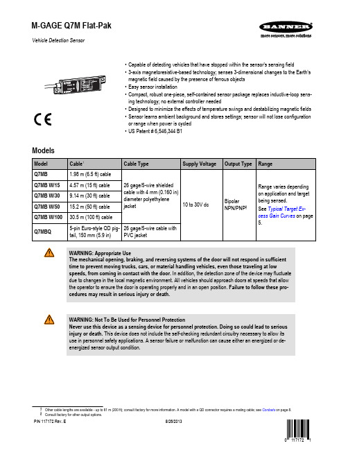
Vehicle Detection Sensor•Capable of detecting vehicles that have stopped within the sensor's sensing field•3-axis magnetoresistive-based technology; senses 3-dimensional changes to the Earth’smagnetic field caused by the presence of ferrous objects•Easy sensor installation•Compact, robust one-piece, self-contained sensor package replaces inductive-loop sens-ing technology; no external controller needed•Designed to minimize the effects of temperature swings and destabilizing magnetic fields•Sensor learns ambient background and stores settings; sensor will not lose configurationor range when power is cycled•US Patent # 6,546,344 B1ModelsWARNING: Appropriate UseThe mechanical opening, braking, and reversing systems of the door will not respond in sufficienttime to prevent moving trucks, cars, or material handling vehicles, even those traveling at lowspeeds, from coming in contact with the door. In addition, the detection zone of the device may fluctuatedue to changes in the local magnetic environment. All vehicles should approach doors at speeds that allowthe operator to ensure the door is operating properly and in an open position. Failure to follow these pro-cedures may result in serious injury or death.WARNING: Not To Be Used for Personnel ProtectionNever use this device as a sensing device for personnel protection. Doing so could lead to seriousinjury or death. This device does not include the self-checking redundant circuitry necessary to allow itsuse in personnel safety applications. A sensor failure or malfunction can cause either an energized or de-energized sensor output condition.Cordsets on page 8.M-GAGE Q7M Flat-PakP/N 117172 Rev. E8/26/2013OverviewThe M-GAGE Q7M Flat-Pak sensors implement a passive sensing technology to detect large ferrous objects. The sensor measures the change in the Earth’s natural magnetic field (the ambient magnetic field) caused by the introduction of a ferromagnetic object.The M-GAGE Q7M Flat-Pak sensors provide an alternative to inductive loop systems.Mount the Q7M sensor above-ground (see Installation on page 3).Theory of OperationThe sensor uses three mutually perpendicular magnetoresistive transducers.Each transducer detects magnetic field changes along one axis. By incorporat-ing three sensing elements, maximum sensor sensitivity is achieved.A ferrous object will alter the local (ambient) magnetic field surrounding the ob-ject, as shown in Figure 1. on page 2 and Figure 2. on page 2. The mag-nitude of this magnetic field change is dependent both on the object (size,shape, orientation, and composition) and on the ambient magnetic field (strength and orientation).During a simple programming procedure, the Q7M sensor measures the ambi-ent magnetic field. When a large ferrous object (for example, a truck, automo-bile, or rail car) alters that magnetic field, the sensor detects the magnetic field changes (anomalies). When the degree of magnetic field change reaches the sensor’s threshold, the sensor’s discrete outputs switch.Sensor Field of View and RangeThe sensor range depends on three variables:1.The local magnetic environment (including nearby ferrous material)2.The magnetic properties of the object to be sensed3.Sensor settingsThe Q7M sensor can detect changes in the ambient magnetic field in all direc-tions. As with other sensors, the range will depend on the target. The strong disturbance of a large ferrous object decreases as the distance from the sensor increases, and the magnitude and shape of the disturbance is dependent on the object’s shape and content.The sensor can be programmed to react to magnetic field disturbances of great-er or lesser intensity using two adjustments: background condition and sensitivi-ty level.Once background condition and sensitivity level are set, the sensor is ready todetect the target object. Both settings are stored in non-volatile memory.NOTE: The Q7M sensor will continue to sense a vehicle in its sensing field, even when the vehicleis stopped.ces caused by permanent ferrous-metal objectswithin or near the sensor.Figure 2.B. After a large steel target object is introduced,the sensor detects the differential (magnetic strength and orientation) between fields A and B.If the differential is greater than the sensitivity threshold, the sensor’s outputs conduct.M-GAGE Q7M Flat-PakTip: Sensor may be mounted inside a non-ferrous architectural detail for cosmetic or security reasons. It is important that, wherever it is mounted, the sensor is securely attached during configuration and all later use.If the sensor moves after being taught, detection errors may occur and sensor must be re-taught. If a sensor appears to lose its taught settings, it may be a result of having shifted position after setup.InstallationThe M-GAGE Q7M Flat-Pak is non-directional, and can be mounted in any position. The sen-sor may be mounted inside a non-ferrous architectural detail for cosmetic or security reasons.The end caps provide mounting holes at either end of the sensor. The sensor can be mounted to any desired surface (for example, cement or metal). Select a location as close as possible to the vehicle(s) to be detected.In applications where the sensor is mounted to the side of the vehicle traffic lane (for example,in a kiosk, menu board, or gate control box), consideration must be made for movement of metallic objects within a few feet of the sensor on the opposite side of the traffic lane, even if the activity is not visible (for example, behind a wall or inside a building). Consult Banner Ap-plications Engineer for further information.When mounting a QD-cable model, it is recommended to route the cable through conduit forprotection from environmental conditions. The integral cable does not need such protection.Figure 3. Installation using the mounting holes in the sensor'send capsMake sure that the sensor is securely attached during configuration and operation. If the sensor moves after being taught, detection errors may occur and the sensor must be re-taught. If a sensor appears to lose its taught settings, it may be a result of having shifted position after setup.Install the Sensor Above GroundRestriction: The models listed in this datasheet are not intended to be installed below ground due to inher-ent installation and environmental variability. Contact Banner Engineering for models designed for below ground installations.Installation Placement ConsiderationsFigure 4. Example good sensor placementGood PlacementFigure 4. Example good sensor placement on page 3shows an example of appropriate M-GAGE sensor placement for vehicle detection. The sensor is placed at the edge of a traffic lane to detect the vehicle in the near lane. This type of placement is often used for a kiosk,menu board, or gate control box.M-GAGE Q7M Flat-PakFigure 5. Example bad sensor placementBad PlacementFigure 5. Example bad sensor placement on page 4 de-picts a potential problem installation. While mounting the sensor at the side of a lane may be successful, this mounting location increases the potential for detection problems. To reliably detect a vehicle from the side, the sensor sensitivity must be increased in order to see ob-jects further away in the lane of interest. Unfortunately,this enables the sensor to also detect another object op-erating behind the sensor or vehicles in adjacent lanes,which will cause false counts.Place the M-GAGE sensor at the edge of a traffic lane only if there is no possibility of other objects being de-tected by the sensor. A good practice is to ensure that no vehicles will be within 3.05 m (10 ft) of the sensor on the non-traffic side.Sensor ConfigurationThe sensor is configured via its gray Remote wire. The gray wire is always active and the sensor may be re-configured at any time. For optimum performance, secure the sensor so that it will not move either during or following the configuration.Programming pulses may be executed by connecting the sensor's gray wire to the sensor's blue (common) wire with a normally open mechanical button connected between them, or as a low (< 2V dc) signal from a programmable logic controller (PLC), or using the model DPB1 Portable Programming Box, as shown in Figure 7. Connecting to the model DPB1 Portable Programming Box on page 4. When a PLC is used for configuration, the pulses are acknowledged via the sensor output signal.When the DPB1 is used, the pulses are accomplished by clicking the DPB1 TEACHpush button (0.04 seconds ≤ click ≤ 0.8 seconds).The sensor's output status is reflected by the DPB1 Output indicator LED.Configuration/Output ON LED Yellow)Power ON LED(Green)Figure 6. Sensor FeaturesFigure 7. Connecting to the model DPB1 Portable Programming BoxBrown Blue Gray White or BlackPush "TEACH" button to pulse the remote wire.M-GAGE Q7M Flat-PakConfigurationSet Background Condition (No Vehicle Present)Wire the M-GAGE ™ sensor as directed. Remove all vehicles and all other metal objects that are temporarily in the sensing area before setting the background condition.Set Sensitivity LevelLevel 1 = least sensitive, Level 6 = most sensitive.Typical Target Excess Gain CurvesAfter the sensor has been securely mounted and configured, it is ready to operate. The fol-lowing example application shows typical responses for the M-GAGE ™ sensor.Figure 8. Application example: sensor mounted 1 meter (3.3 ft) above ground on page 6describes mounting the M-GAGE ™ 1 meter (3.3 ft) above the ground to sense an automo-bile. The graph shows the excess gain for a typical car. Excess gain is a measure of the amount of extra signal detected by the sensor over and above the Level needed to detect the target. This example assumes a Level 5 sensitivity threshold.Excess Gain vs Sensitivity Level(Assumes Level 53)M-GAGE Q7M Flat-PakThe table at right compares the change in excess gain if the sensitivity Level changes. If the sensitivity is at Level 6, then the excess gain at a given distance would be 1.3 times larger than for a Level 5 sensitivity. Conversely, if the sensitivity threshold is Level 1, then the ex-cess gain would be one third as big as for Level 5.M-GAGEis not a factor.Distance from Vehicle SideE x c e s s G a i n (S e n s i t i v i t y L e v e l )012345678Figure 8. Application example: sensor mounted 1 meter (3.3 ft) above groundSpecificationsSupply Voltage10 to 30V dc (10% max. ripple) at 43 mA, exclusive of loadAbove +50° C (+122° F), supply voltage is 10 to 24V dc (10% max. ripple)Sensing RangeSee Figure 8. Application example: sensor mounted 1meter (3.3 ft) above ground on page 6Sensing TechnologyPassive 3-axis magnetoresistive transducer Supply Protection CircuitryProtected against reverse polarity and transient voltag-esOutput ConfigurationTwo SPST solid-state outputs conduct when object is sensed; one NPN (current sinking) and one PNP (cur-rent sourcing)Output ProtectionProtected against short-circuit conditionsAdjustmentsConfiguration of Background Condition and Sensitivity Level may be set by pulsing the gray wire remotely via the portable programming box (see Configuration on page 5)IndicatorsTwo indicators (see Figure 6. Sensor Features on page 4)Power Indicator: GreenConfiguration/Output Indicator: Red/Yellow Remote TEACH InputImpedance 12K ohms (low = < 2V dc)ConstructionLightpipes: AcrylicHousing: Anodized aluminumEnd Caps: Thermoplastic polyester Operating Conditions−40 °C to +70 °C (−40 °F to +158 °F)100% maximum relative humidity ConnectionsShielded 5-conductor (with drain) polyethylene jack-eted attached cable or 5-pin Euro-style quick-discon-nect PVC pigtail (see Cordsets on page 8)Environmental RatingLeak proof design is rated IEC IP69K; NEMA 6PM-GAGE Q7M Flat-PakOutput Ratings100 mA maximum (each output)NPN saturation: < 200 mV at 10 mA and < 600 mV at 100 mANPN OFF-state leakage current: < 200 microamps PNP saturation: < 1.2V at 10 mA and < 1.6V at 100 mAPNP OFF-state leakage current: < 5 microamps Output Response Time20 millisecondsDelay at Power-Up0.5 secondsTemperature Effect< 0.5 milligauss / ºC Vibration and Mechanical ShockAll models meet Mil. Std. 202F requirements method 201A (vibration: 10 to 60Hz max., double amplitude0.06 in, maximum acceleration 10G). Also meets IEC947-5-2: 30G 11 ms duration, half sine wave. PatentU.S. Patent 6,546,344 B1CertificationsDimensions7.5 mm (0.30")19 mm(0.75")10.0 mm(0.39")CableorQD PigtailMaximum AllowableTorque: 7 in - lbs Hookups+10 - 30V dc–+10 - 30V dc–1 = Brown2 = White3 = Blue4 = Black5 = Gray AccessoriesM-GAGE Q7M Flat-PakM-GAGE Q7M Flat-PakCordsetsBanner Engineering Corp Limited WarrantyBanner Engineering Corp. warrants its products to be free from defects in material and workmanship for one year following the date of shipment. Banner Engineering Corp. will repair or replace, free of charge, any product of its manufacture which, at the time it is returned to the factory, is found to have been defective during the warranty period. This warranty does not cover damage or liability for misuse, abuse, or the improper application or installation of the Banner product.THIS LIMITED WARRANTY IS EXCLUSIVE AND IN LIEU OF ALL OTHER WARRANTIES WHETHER EXPRESS OR IMPLIED (IN-CLUDING, WITHOUT LIMITATION, ANY WARRANTY OF MERCHANTABILITY OR FITNESS FOR A PARTICULAR PURPOSE), AND WHETHER ARISING UNDER COURSE OF PERFORMANCE, COURSE OF DEALING OR TRADE USAGE.This Warranty is exclusive and limited to repair or, at the discretion of Banner Engineering Corp., replacement. IN NO EVENT SHALL BANNER ENGINEERING CORP. BE LIABLE TO BUYER OR ANY OTHER PERSON OR ENTITY FOR ANY EXTRA COSTS, EXPEN-SES, LOSSES, LOSS OF PROFITS, OR ANY INCIDENTAL, CONSEQUENTIAL OR SPECIAL DAMAGES RESULTING FROM ANY PRODUCT DEFECT OR FROM THE USE OR INABILITY TO USE THE PRODUCT, WHETHER ARISING IN CONTRACT OR WAR-RANTY, STATUTE, TORT, STRICT LIABILITY, NEGLIGENCE, OR OTHERWISE.Banner Engineering Corp. reserves the right to change, modify or improve the design of the product without assuming any obligations or liabilities relating to any product previously manufactured by Banner Engineering Corp.。
车辆检测器用户使用手册及协议

交通事件检测器(CP-TFCS01)使用说明书普天首信广州哈迪目录1.硬件 (6)1.1.CP-TFCS01车辆检测器机架描述 (6)1.1.1.机架面板视图 (6)1.1.2.车辆检测器互连框图 (7)1.2.电源板 (7)1.3.通信板 (7)1.4.检测板 (8)2.设置 (8)2.1.通信板设置 (8)2.1.1.复位 (8)2.1.2.地址跳线 (9)2.1.3.其它参数设置 (9)2.2.检测板设置 (10)2.2.1.复位 (10)2.2.2.灵敏度设置(SENS) (10)2.2.3.存在时间设置(PRES) (10)2.2.4.工作频率设置(FREQ) (11)3.通信 (11)4.环形线圈安装 (12)4.1.环形线圈检测的基本原理 (12)4.2.线圈线 (12)4.3.线圈的尺寸 (13)4.4.线的绞接 (13)4.5.线圈的安装 (13)4.6.线圈填充物 (14)4.7.线圈接入检测器 (14)4.8.线圈安装注意事项 (14)5.检测数据范围 (15)6.故障分析及解决 (15)6.1.供电故障 (15)6.2.线圈检测板故障 (15)6.3.通信板故障 (16)7.1.命令1:设置日志周期 (18)7.2.命令2:设置逻辑线圈 (18)7.3.命令3:设置全部参数 (19)7.4.命令4:设置时间日期 (21)7.5.命令5:查询交通数据 (21)7.6.命令6:查询告警事件 (22)7.7.命令7:查询日志记录 (22)7.8.命令8:查询车道计数 (23)7.9.命令9:清除车道计数 (24)7.10.命令10:查看门狗状态 (24)7.11.命令11:重启动检测板 (25)7.12.命令12:远程系统重启 (25)7.13.命令13:更改通信速率 (25)7.14.命令14:检测器初始化 (26)7.15.命令15:查询检测日志 (26)7.16.查看串口通信数据 (27)7.17.重复发送命令 (27)8.一般设置步骤 (27)1通信协议 (29)1.1通信代码 (29)代码(1)交通逻辑配置的设定 (29)代码(2)查询交通逻辑配置 (30)代码(3)返回交通逻辑配置数据 (30)代码(4)设置检测器的日志周期 (31)代码(5)查询日志周期 (31)代码(6)返回日志周期 (31)代码(7)查询最后一次的日志记录 (31)代码(8)最后一次的日志记录有效 (31)代码(9)最后一次的日志记录无效 (31)代码(10)查询指定日志记录 (31)代码(11)返回指定日志记录 (31)代码(12)指定日志记录号无效 (31)代码(14)请求报警阈值 (32)代码(15)报警阈值数据 (32)代码(16)活动报警数据 (32)代码(17)查询检测器故障状态 (33)代码(18)返回检测器故障状态 (33)代码(19)设置时间日期 (33)代码(20)查询时间日期 (33)代码(21)返回时间日期数据 (33)代码(24)车型长度分类 (34)代码(25)查询长度分类类型 (34)代码(26)返回长度分类数据 (34)代码(27)查询膝上电脑操作状态 (34)代码(28)返回膝上电脑操作状态 (34)代码(29)查询活动报警数据 (35)代码(47)查询主交通数据 (35)代码(49)设置平滑因子P (35)代码(50)查询平滑因子 (35)代码(51)返回平滑因子 (35)代码(53)查询WATCHDOG状态 (35)代码(54)返回WATCHDOG数据 (35)代码(55)查询当前日志记录索引 (36)代码(56)返回当前日志记录索引 (36)代码(101)检测器初始化 (36)代码(102)设置单元地址、线圈尺寸、线圈间距 (36)代码(103)查询线圈尺寸、线圈间距 (36)代码(104)返回当前线圈尺寸、线圈间距数据 (36)代码(126)查询检测日志 (36)代码(127)返回当前检测日志 (36)2.默认设置 (38)2.1报警 (38)2.2.数据日志 (38)2.2.1车长分类数据(BIN) (38)2.2.2日志周期 (39)2.3.时间与数据 (39)2.4.交通逻辑配置 (39)2.5.平滑因子 (39)2.6.日志索引 (39)3.数据保存 (39)4.数据日志 (39)4.1存储要求 (40)4.2日志数据传送 (41)4.3推荐操作 (41)1.硬件1.1.CP-TFCS01车辆检测器机架描述CP-TFCS01型车辆检测器由一个10英寸机架以及电源板、通信板和1~5块检测板组成。
METTLER TOLEDO金属探测器服务支持包说明书

/metaldetectionFor more informationThe full service and support package available from METTLER TOLEDO includes:• Installation andcommissioning support • Operator andmaintenance training • Certified test samples • Initial and ongoing performance verification • Spare parts and spares kits • Equipment repairsWhen you invest in a piece of METTLER TOLEDO equipment, you are assured of the highest build quality, consistent performance and maximum reliability, but that is just the start of the relationship.Our sales and service engineers provide initial guidance on selecting the correct system solution to suit your needs.Once your system has been installed and commissioned, you can be sure that a METTLER TOLEDO trained service expert is never far away.Our team is ready to give ongoing support throughout the life of the system.Customer SupportMETTLER TOLEDO Group Product Inspection DivisionLocal contact: /contactsSubject to technical changes© 09/2012 Mettler-Toledo Safeline Limited SLMD-IN-BRO-EN-ASNCONV-0616Conveyorised Metal Detectors Flexible Configuration Consistent PerformanceMeeting Compliance NeedsM e t a l D e t e c t i o nSeries 40, MB, 60 and 70Flexible Conveyorised Inspection Solutions2Protecting Your CustomersConfigurable to Suit Your ApplicationIn a competitive market place you need to provide your customers with consistent, high quality, contaminant-free products. The Series 40, MB, 60 and 70 Conveyorised Metal Detection range of products provide flexible, inspection solutions to suit a wide range of light to heavy duty food and non-food applications.Tailored to Meet Your Inspection NeedsSystems can be fully configured and built to suit your specific process requirements. Simple stop-on-detection systems through to fully automated detect and reject systems utilising a wide range of product removal devices are available.Conveyorised Metal Detectors provide flexible solutions capable of operating in almost any working environment. This means that whether your product is wet or dry, chilled or frozen, looseor packed, METTLER TOLEDO's range of flexible Conveyorised Metal Detection solutions can address your inspection challenge.C o n v e y o r i s e d M e t a lD e t e c t o r sSeries 40* Conveyorised Metal Detection System with R-Series Profile painted metal detectorSeries 70** Conveyorised Metal Detection System with R-Series Signature metal detector* Series 40 systems are designed for lighter load packages see pages 8 to 9.** Series 70 systems are designed for medium to heavy load packages see pages 10 to 11.Future-Proof Inspection SolutionsDetector apertures, finishes and operational frequencies can be specified to suit your process requirements in order to maximise sensitivity and on line performance. A choice of METTLER TOLEDO metal detection technologies and operating software solutions are available to ensure your quality standards are met.Profile TechnologyThe most advanced metal detection solution available provides the ultimate detection sensitivity to all metals including non-magnetic stainless steels. Profile software also delivers numerous additional features including Product Clustering, Continuous Condition Monitoring and SMS / email communication facilities for maximised process efficiency.Signature TechnologyThe well proven Signature software platformfrom METTLER TOLEDO provides reliablecapability to detect all metal contaminants in amultitude of applications.3C o n v e y o r i s e d M e t a lD e t e c t o r s4Reliable, Consistent PerformanceIn any Working EnvironmentAn Integrated Solution for Dry, Ambient EnvironmentsIn dry, ambient operating environments, painted finishes to both the metal detection head and conveyor frame are sufficient. In some instances a medium duty Stainless Steel (SuS) detector may need to be speci-fied. With IP ratings from a standard IP54 to an IP65 special, systems are capable of withstanding wipe down and light hose down cleaning regimes.Systems of this type can include US Food and Drug Administration (FDA) approved polyurethane (PU) con-veyor belts or can be specified to incorporate modular, polyethylene (PE) belts if required.Suitable for Wet, Chilled and Frozen Products in Extreme EnvironmentsWhen the working environment gets tough, inspection systems need to be specified to equally high standards. The Conveyorised Metal Detection product range can be configured with heavy duty stainless steel detectors rated at IP69K and conveyors sealed up to IP65 standard. Systems of this type are normally designed to include modular polyethylene belts to ensure that the whole system is capable of withstanding high-pressure, hightemperature wash-down regimes and still perform reliably, day after day.The Series 40, MB, 60 and 70 Conveyorised Metal Detection product range can be configured to suit your working environment. This means they deliver consistent performance for maximum process efficiency enabling your business to benefit fromimproved competitiveness and increased productivity with minimum overall operating costs.Conveyors for wet, harsh environmentsR Series Profile detector sealed to IP69K for extreme wash down conditionsSystems include emergency stop buttons as standard5Reliable Performance, Easy IntegrationAll Conveyorised Metal Detection systems are designed and built to exacting standards for long term stability, performance and reliability. Conveyor frames are rigid and robust with fully welded construction. Ledges, flat horizontal surfaces and other dirt traps are minimised ensuring that cleaning is made easy.Effective Product Conveying for Enhanced Process EfficiencyHigh quality motors and drives are utilised to ensure product is transported positively and consistently through the detector. A choice of fixed speed, direct drive motors are available to meet most demands. Alternatively, variable speed drives can be specifiedwhen required.Further Options for a Tailored SolutionOther options can be specified to further aid operational efficiency and product transfer effectiveness including the incorporation of product guides to provide full control of the product as it passes through the system.C o n v e y o r i s e d M e t a lD e t e c t o r s6Fail Safe SystemsFor Complete Peace of MindThe Conveyorised Metal Detection product range can be configured to meet andexceed the demands of all leading retailer and other industry or regulatory standards. An extensive range of options from simple pack sensing devices through to sophisticated closed loop failsafe systems are available.Systems provide a future proof solution with the option to retro-fit failsafe systems at a later stage enabling the system to grow and evolve with your needs and the needs of your customers.Data Collection via USB SticksThe detectors used within the product range can be configured to incorporate ports to support external devices such as USB sticks to collect data. Information gathered can be used to generate data tickets or provide electronic records. When more sophisticated automated data collection is required, systems can incorporate advanced connectivity solutions ranging from a simple serial connection to full Ethernet network connectivity whichcould include wireless functionality.Warning beacons and soundersKey re-set (shown) and push button systems availablePack sensorsDevices and Systems Available Include:• Warning beacons and sounders • Push-button and re-set systems • Pack in-feed sensors• Reject confirmation sensors • Bin-full sensors• Detector head fault warning • Air failure alarm •Shaft encoderSeries 70 Conveyorised System with R-Series Signature metal detectorRemoving the Right Contaminated Product Every TimeOnce identified, metal contaminated product or packs need to be safely and effectively removed from the production line. Rejecting the right pack every time without compromising process efficiency requires the system to be specified correctly with sophisticated timing and process control measures. Important factors to consider can include the need to meet compliance requirements and the characteristics of the product and process, for example, the pack size and line speed.Stop on Detect FunctionalityThe simplest solutions enable the conveyor to be stopped on the detection of metal contamination. Contaminated product can be manually removed before re-starting the system. The effectiveness of these basic systems can be supplemented through the use of optional warning sounders, high visibility beacons and other secure system re-set features.A Choice of Automatic Reject SystemsThe Series 40, MB, 60 and 70 Conveyorised Metal Detection product range can be configured with a host of dynamic, fully automated reject systems. For pack products the reject systems include photo-gated timers to ensure the correct pack is rejected every time. These systems can also be supplemented with the full range of optional warning devices, reject product collectionbins and innovative fail safe systems to further support compliance.Integrated Reject Options Available Include• Air Blast Reject Systems • Pusher Reject Systems*• End Flap Systems*• Sweep Arm Diverter*•Reject BinsAir Blast Reject SystemsPusher Reject SystemsSweep Arm DiverterEnd Flap SystemsRejection Mechanism Capability Table* These systems need be chosen as per configuration and rejection mechanism capability tables.** Reject Bin can only match with Pusher and Air Blast rejections.7Reject BinC o n v e y o r i s e d M e t a lD e t e c t o r s8Series 40 and Series MBConveyorised Inspection SolutionsAvailable in different lengths and widths, Series 40 Conveyorised Systems are designed to be used for light load packed applications with the Series MB solution being utilised in wet harsh processing and packed product line production.Systems are suited for integration into production lines or can be utilised in stand alone applications.Such solutions can form Critical Control Points (CCP's) in a production process to support compliance with local regulatory and international food standards.The system can be designed and built to suit your specific process requirements from simple stop-on-detection, to fully automatic detect and reject systems.Series 40 and Series MB Configuration TablesSeries 40Series MBChoice of Aperture Size••Choice of Conveyor Length and Height ••Conveyor Frame Materials Mild Steel – White Painted •Stainless Steel – Brushed••Fixed Conveyor Speed *•Stop-on-Detection ••Beacon Sounder••Rejection MechanismEnd Flap••Pusher••Sweep Arm Diverter ••Air Blast ••System OptionsProduct Guide ••Pack Sensor••Reject Bin ••Emergency Stop••Variable Conveyor Speed *••* For speed value refer to the conveyor speed tablesSeries MB Conveyorised System with R-Series Profile SuS DetectorSeries 40 and Series MB Product Application RangeSeries 40Series MBApplication Environment Dry product (discrete, small pack)Dry, wet or frozen product (processed, block, pack)Product Size Length≤1000 mm≤1000 mm Width≤200 mm≤400 mm Height ≤150 mm≤300 mm Weight≤10 kg≤30 kgSeries 40 and Series MB Size RangeSeries 40Series MB Conveyor Belt Material PU*Modular PE**Outline Dimensions (mm)Length (Lc)1000~12001200~2000 Width (Ws)800~900800~1100 Height (Hc)550~1000550~1000Maximum Load (kg)1040 MD Aperture Size (mm)Width (Wa)200~300200~500Height (Ha)75~20075~350 Series 40 and Series MB Speed ConfigurationSeries 40 (m/min)Series MB (m/min)Fixed Speed 0.25Kw Not applicable20, 330.55Kw Not applicable16, 19, 25, 35Variable Speed 18~28 18~28 25~4025~40 35~5035~50Note: Speed value tolerance ±10%9 PU* = Polyurethane PE** = PolyethyleneC o n v e y o r i s e d M e t a lD e t e c t o r s10Series 60 and Series 70Conveyorised Inspection SolutionsSeries 60 and Series 70 Configuration TablesSeries 60Series 70Choice of Aperture Size••Choice of Conveyor Length and Height ••Conveyor Materials Mild Steel – White Painted ••Stainless Steel – Brushed••Fixed Conveyor Speed *••Stop on Detection ••Beacon Sounder••Rejection MechanismEnd Flap••Pusher•Sweep Arm Diverter •Function OptionsProduct Guide ••Pack Sensor••Reject Bin •Emergency Stop••Variable Conveyor Speed *••* For speed value refer to the conveyor speed tablesFor larger product applications, the Series 60 and Series 70 Conveyorised Systems provide a flexible conveyor and detection solution well suited to medium and larger packed products.Systems can be integrated efficiently into a production line or utilised for stand alone applications.System design is flexible with a range of configurations enabling diverse solutions to be developed to suit specific process requirements from simple stop-on-detection systems to fully automatic detect and reject mechanisms.Series 70 Conveyorised System with R-Series Signature metal detector11Series 60 and 70 Size RangeSeries 60Series 70Conveyor Belt MaterialPU*PU*Outline Dimensions (mm)Length (Lc)1200~24001200~2400Width (Ws)900~11001100~1400Height (Hc)550~1000550~1000Maximum Load (kg)5050MD Aperture Size (mm)Width (Wa)300~600650~800Height (Ha)75~45075~450Series 60 and 70 Speed ConfigurationSeries 60(m/min)Series 70(m/min)Fixed Speed0.25Kw 20, 27, 35, 41, 4831, 39, 480.55Kw21, 28, 35, 43, 5021, 28, 35, 40, 50Variable Speed18~28 18~28 25~4025~40 35~5035~50Note: Speed value tolerance ±10%Series 60 and 70 Product Application RangeSeries 60Series 70Application EnvironmentDry Product (discrete, big bag, pack)Dry Product (discrete, block, pack)Product SizeLength≤2000 mm ≤2000 mm Width ≤500 mm ≤700 mm Height ≤400 mm ≤400 mm Weight≤30 kg≤30 kgPU* = Polyurethane。
TI110系列便携式辐射测温仪使用说明书

氧化
非氧化
锌 镀锌铁板
发射率
0.04—0.06 0.55
0.11—0.25 0.02—0.05
0.20 0.6—0.88
0.10 0.40—0.60
0.05 0.05 0.11 0.30—0.50 0.05—0.07 0.40 0.30—0.60 0.05 0.25
材料
石棉
℃
更换电池 按整机结构图所示,将序号 7 电池仓盖向下拔出,取出旧电池,更换新电池, 再将电池仓盖向上推到位即可。 透镜的保护与清洁 保持清洁、避免摔震、避免受潮、避免长时间放置高温处是透镜的基本保护 措施。另外还需要注意的一点是寒冷季节从室外进入室内,镜面会凝结水气,切 忌擦拭,可让它自行散去。 当透镜上沾有灰尘或霉斑,先用橡皮球把透镜表面灰尘吹去,再用镜头刷或 镜头纸轻揩,擦时要从透镜的中心轻轻向周围擦,切忌直擦,用力要轻,以免把 透镜擦毛。
在不扣板机的情况下,按一下“方式”键,上次最后的温度值会重新显示出来, 继续按“方式”键,将顺序调出最大值、最小值、差值和平均值。
→ NORMAL → MAX → MIN → ∆T → AVG →
Last value
Last value
Last value
Last value
Last value
高/低温报警 当测量的温度高于高温报警设定值或者低于低温报警设定值时,此时若高
≤10mA
92 mm×191 mm×50mm
260g
TI110L
-20~500℃ ±1%或±1℃
取最大 ±1℃ 8:1 8~14μm 0.95 固定 ≤700ms 1℃或 1
√
√ √ √ √
√ 0℃~+40℃
非凝结状态下,达 到 40℃时为 10%~ 80% -40℃~+60℃
- 1、下载文档前请自行甄别文档内容的完整性,平台不提供额外的编辑、内容补充、找答案等附加服务。
- 2、"仅部分预览"的文档,不可在线预览部分如存在完整性等问题,可反馈申请退款(可完整预览的文档不适用该条件!)。
- 3、如文档侵犯您的权益,请联系客服反馈,我们会尽快为您处理(人工客服工作时间:9:00-18:30)。
线圈型车辆检测器使用说明NO:9001- 0110-232■ 安装检测器 ■ 接线图车辆检测器必须安装在离检测线圈尽可能近的防水、防潮的干燥环境里。
安装位置必须选择在远离热源、强磁场的地方,其四周应与其它装置保持至少10毫米的距离(请勿紧贴机箱安装)。
检测器能否良好工作在很大程度上取决于它所连接的检测地感线圈。
埋设线圈的几个重要参数包括:环境(回避高温、强磁、可移动金属等)、材料、线圈形状大小、匝数、埋设方法(参见《线圈安装指南》)。
■ 使用及工作指示接通电源后,检测器将会自动校准。
校准过程约3秒。
校准进行时,面板上的LED 会闪烁(亮0.5秒,灭0.5秒)几次。
在校准期间,不应有车停在线圈上。
当校准成功后,面板上的“检测”指示灯熄灭,当线圈上有车通过时,面板上的“检测”指示灯亮起,且存在输出继电器2(3、4脚)吸合导通;若在校准过程中未检测到线圈或线圈电感值不在允许范围内,对应的LED 指示灯会不停地闪烁。
其闪烁情况如下:线圈未连接: 线圈电感太小: 线圈电感太大:■ 工作频率调节本产品提供两种频率选择,用户可以更改线圈的工作频率以避免相邻线圈或环境频率的干扰。
先取下检测器顶端的黑色面盖,拔动主板上的拔码开关DIP5即可调整工作频率。
DIP5拔至ON 时为低频,DIP5拔至OFF 时为高频。
■ 灵敏度调节灵敏度调节使用面板上的滑动开关,有三档:H 为高灵敏度,M 为中灵敏度,L 为低灵敏度。
在试运行时,先将灵敏度设在较低档位,在实际测试后如果车辆检测没有反应,则应将灵敏度调高一档,如此反复,直至车检器稳定、正常工作。
[注意]:如果线圈不能正常工作,应首先检查线圈埋设情况(连接线是否双绞、破损等);然后再调整工作频率或灵敏度级别。
■ 继电器输出方式继电器2(3、4、11脚)输出方式由拔码开关DIP3决定:当DIP3拔至OFF 时为存在输出,即如有车辆进入线圈时,3、4脚吸合导通,直至车辆离开线圈;当DIP3拔至ON 时,继电器2的输出与继电器1的输出方式相同(由DIP1和DIP2决定)。
继电器1(5、6、10脚)为多功能输出,其输出方式由主板上拔码开关DIP1和DIP2决定。
DIP1为OFF 、DIP2为OFF 时,在车辆离开线圈300毫秒后,5、6脚吸合导通1秒后断开;DIP1为ON 、DIP2为OFF 时,如有车辆进入线圈,5、6脚立即吸合导通并于300毫秒后断开; DIP1为OFF 、DIP2为ON 时,如有车辆进入线圈300毫秒后,5、6脚吸合导通直至车辆离开; DIP1为ON 、DIP2为ON 时,如有车辆进入线圈,5、6脚立即吸合导通并于车辆离开后再延时300毫秒后断开;■ 检测器复位当检测器上电时,或改变面板上灵敏度开关时,检测器会进行复位操作。
在复位后,检测器会被初始化为无车状态。
■ 技术参数工作电压: 230V AC 、115V AC 、24V DC/AC 、12V DC/AC 可选,详见机身标签 电压公差:交流: +10% / -15%直流: ±15%额定功率: 4.5W输出继电器: 240V/5 A AC ; 工作温度: -20℃至+65℃; 存储温度:-40℃至+80℃;工作频率: 20KHz 至170KHz ; 反应时间: 100毫秒; 存在时间: 无限存在 灵 敏 度: 三级可调线圈电感量: 50uH 至1000uH (最佳100uH 至300uH ); 线圈连接线: 最长20米,每米至少双绞20次; 尺寸 (含底座): 78×40×108毫米 (长×宽×高)VEHICLE LOOP DETECTOR USER ’S GUIDENO :9001-0110■ Install Detector■ Wiring DiagramThe loop detectors must only be placed in dry rooms or control cabinets that are protected against all types of moisture and wetness. A distance of at least 10 mm from other devices must be maintained on each side. The ambient temperature must not exceed 65° C. The installation of the induction loop is described in other operating instructions.■ Operation and IndicationWhen the power is applied, the red Power LED will glow and the detector is tuning, the green Check LED blink about 3 seconds. The green LED will also glow whenever a vehicle is detected passing over the inductive loop. If a loop fault exists the green LED will come on and flash indicating a fault.Loop no connected: Loop too small: Loop too large:■ FrequencyTo eliminate interference of two neighbouring wire loops or loop detectors, the frequency can be altered by DIP5 on the main board in the box.■ SensitivityThe response sensitivity can be set using the threestage switch on the front. The sett ing “L” corresponds to the lowest sensitivity. “M” is the medium sensitivity and “H ” is the highest sensitivity.After the sensitivity has been set, a reset and a calibration automatically takes place.【Attention 】 If the detector isn ’t working normally, you must check the loop and wiring at first, and then alter the frequency or the sensitivity.■ Output RelayThe output of relay 2 can be programmed by means of DIP3 Switch.If DIP3 is “OFF ” site, the output is presence output. When a vehicle is detected passing over the inductive loop, the relay 2 is energized( Pin3 and Pin4 is shorted) until the vehicle is detected leaving the loop. If DIP3 is “ON ” site, the output of redlay 2 is same as relay 1.The output of relay 1 can be programmed by means of DIP1 and DIP2 Switch. DIP1 DIP2 Output mode of relay1OFF OFF When a vehicle is detected leaving the loop, relay1 is energized 1 S after 300 mS. ON OFF When a vehicle is detected passing the loop, relay1 is energized at once anddisconnect after 300ms.OFF ON When a vehicle is detected passing the loop after 300ms, relay1 is energized until thevehicle is detected leaving the loop.ON ON When a vehicle is detected passing the loop, relay1 is energized until the vehicle isdetected leaving the loop after 300 mS.■ ResetThe detector automatically reset and tune to the inductive loop when the power is applied, whether on initial installation or after any break in power supply. Should it be necessary to retune the detector, as may be required after changing any of the switches or after moving the detector from one installation to another.■ T echnical DataSupply voltage :230V AC , 115V AC, 24V DC/AC, 12V DC/AC( See the label on the detector) V oltage tolerance AC: +10% / -15% V oltage tolerance DC: ±15% Power Consumption: 4.5V A Output relays: 240V/5A Operating temperature: -20°C to +65°C Storage temperature: -40°C to +85°C Frequency range: 20 kHz to 170 kHzReaction time: 100ms Signal holding time: UnlimitedSensitivity: Adjustable in 3 incrementsLoop inductance: Total loop plus connection wiring: 50μH to 1000μH. Ideal is 100μH to 300μHLoop connection wiring: Maximum length 20 meters, twisted at least 20 times per meter Size of Housing:78x40x108 mm (L x W x H)。