TracePro 中文教程
Tracepro学讲义习教程
Tracepro的系统设置
View>Customize
此处可以设置Tracepro操 作界面中运行方面的参数, 如导航区的位置,模型的 显示方式,模型的颜色, 背景的颜色等等。
13.01.2021
Tracepro模拟步骤
建立模型 光学特性 光源设定 分析功能
13.01.2021
13.01.2021
File>Open
Insert>Part
Tracepro建模
光学软件建模
同时,Tracepro可 以将其他程序建好 的模型,直接读取, 简单方便。如图, 通过Tracepro打开 OSLO文档
13.01.2021
Tracepro光学 模型进行属性的设置光学特 性在Tracepro的模拟中非常 重要,模拟的目的是模拟结 果与实际更为接近。所以光 学特性的定义就是给模拟效 果一个好的起始。
光学软件建模
Tracepro与很多光学模拟软件如ZEMAX,OSLO,Code V等是共用的, 所以可以直接用Tracepro打开这些软件保存的文档。
13.01.2021
Tracepro建模
Tracepro自建模
Tracepro软件本身提供了一个强大 的模型库,使用者可以根据自己的 需要选择不同的模块来建立模型。 其路径就是 :Insert>
Tracepro中并未涵 盖所有我们需要 的介质,但是在 Tracepro中可以根 据自身的需要编 辑特定的面,材 料,薄膜,折射 率等光学介质。
13.01.2021
Tracepro光源设定
Tracepro光源的设定有三种方法:
1.Tracepro自建光源模型,然后进行光源属性定义. 2.Tracepro光源库,其中有部分已经定义好光源参数的光 源 实体模型。 3.光源文件导入。Insert>Source选择需要插入的光源文件.对 于光源文件,有几种符合的格式(*.ray,*.dat,*.src)
TracePro 7.0用户手册_BSDF译文
ABg BSDF 模型
在 Tracepro 中的 BSDF 函数模型是一种叫做 ABg 的逆幂律模型, 之所以被叫做 ABg 模型是因为在它的表达 式中 A,B,g 有三个参数,
BSDHale Waihona Puke A B - 0g
(7.25)
在式中,A,B,g 参数可以由测量的数据去拟合公式得到。
下图为一个典型的 ABg 模型的 BSDF 函数图,分布在 log-log:
2 / 2
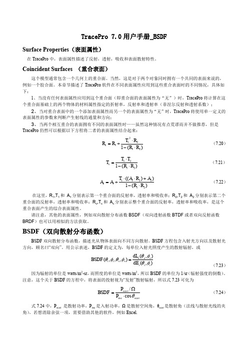
TS
BSDF ( , , , ) cos sin (d )d
i i s s 0 0
(7.28)
在式 7.28 中,θ和φ是在球极坐标即 Z 轴为平面法向下的定义,当入射光照到表面上,θi 和φi 为 0,θs= θ,φs=φ,此时 TS 为:
2 / 2
Harvey-Shack BSDF(哈维 BSDF 模型)
Harvey 在其论文(J.E. Harvey, “Light-Scattering Properties of Optical Surfaces, Ph.D Dissertation, U. Arizona, 1976” J.E. Harvey, 光学表面的光反射特性,博士论文,亚利桑那大学)中论述,对于大多光学表面,如果 表示为余弦项而非角度项,则 BSDF 与入射光方向无关。类比线性系统理论,Harvey 称此特性为“平移不变 性”。在图 7.4 中,β0 是单位矢量 r0 在镜面方向上的投影,β 是单位矢量 r 在散射方向上的投影,两者之差的 模,|β-β0|是 BSDF 的 argument(是 BSDF 所要讨论的) 。注意,β 和 β0 不是单位矢量!他们是单位矢量的投 影,所以他们的长度小于等于 1. Harvey-Shack 方法给出了一个适用于多数光学表面的模型,即适用于: 散射主要由表面粗糙导致 散射(以及表面粗糙度)是各向同性的 表面粗糙度相对于光波长较小
Tracepro学习教程课件
Tracepro设计实例
分析设计要求
光源 总光通量110lm 半光强角度110度 配光 截光角不应小于27度
半光强角不小于6度 照度 中心光强为4000cd
通过分析,可以得出:设计需要一个聚光的反光杯,且反光杯 的口径与深度的比值接近于1.
2021/6/2
Tracepro设计实例
如图:自定义一 个反射系数为 0.7的反射面。 光线打在此面上 后,将有70%的 光线被反射。
2021/6/2
Tracepro设计实例
反光杯建好后,材料属性也定义完毕,需要根据要求在反光杯的前方 添加3mm的钢化玻璃。
2021/6/2
Tracepro设计实例
模型添加完毕后,最后需要添加一个接受平面。接受平面可以根据实 际需要定义它的大小,位置。模拟完毕后,我们可以从接受平面上得 到有效光效,光斑效果等模拟结果。
2021/6/2
Tracepro的系统设置
View>Customize
此处可以设置Tracepro操 作界面中运行方面的参数, 如导航区的位置,模型的 显示方式,模型的颜色, 背景的颜色等等。
2021/6/2
Tracepro模拟步骤
建立模型 光学特性 光源设定 分析功能
2021/6/2
2021/6/2
Tracepro设计实例
模型添加完毕后,最后需要添加一个接受平面。接受平面可以根据实 际需要定义它的大小,位置。模拟完毕后,我们可以从接受平面上得 到有效光效,光斑效果等模拟结果。
2021/6/2
Tracepro分析功能
照度分析参数设置
如图:照度分析的参数设置表。 Smooting 选定将光斑的显示更 加平滑 Map Count 是照度计算点的数目, 当计算点的数目增大到一定程度 时,照度值也不再变化,此时得 到合适的模拟值
TracePro 4.16中文版
CGTECH产品:
Atd Edit v1.1.34 1Cit v1.1.33 1CD(cnc数控工具机编程软件)
Cam Analyzer v3.2.B.011 1CD(凸轮分析软件)
CIMCO.DNCMax.v4.40.09 1CD(是实现DNC传输网络化、程序管理系统化的软件)
CIMCO Edit v5.11.02 Multilanguage 1CD(中文版,数控程序的编辑与仿真功能,该部分主要实现数控程序的编辑、仿真、文件比较、刀位轨迹模拟等)
CIMCO Software Suite v5.50.37 Multilanguage 1CD(用于存储和检索NC程序、NC程序优化、后处理、以及快速NC程序仿真)
TracePro v4.16光学机构仿真软件
(最新中、英文版;光学机构仿真软件,普遍用于照明系统、光学分析、辐射分析及光度分析的光线仿真)
TracePro 4.16光学仿真软件,是目前市场占有率最高的仿真软件,因为它以ACIS的固体模型为核心,所以使用者在设计分析模型时,可以非常直观的了解其模型。而在赋予其对象材质时,不需特殊的使用技巧,即可完成所有的设定,内建丰富的材料库、表面特性、光源资料库,更是令人惊喜。其功能强大且完整的分析图形及表格,足以应对──车灯相关(HID、LED、Fluorescent、Incandescent……等的灯源)、太空相关(杂散光、鬼影、热效应对影像的影响……等)、显示相关、照明相关、生医相关、雷射组件、消费性电子产品、……等,多产业的应用,是使用者不可或缺的好帮手。
NovaFlow & Solid v2.92r10 for WinXP 1CD
Tracepro学习教程
Tracepro建模
Insert> Lens Element
要点: A.透镜的材料 B.透镜的参数 C.透镜的位置
07.06.2021
Tracepro建模
Insert> Fresnel Lens
要点: A.透镜的材料 B.透镜的参数 C.透镜的位置
07.06.2021
Tracepro建模
光学软件建模
Tracepro与很多光学模拟软件如ZEMAX,OSLO,Code V等是共用的, 所以可以直接用Tracepro打开这些软件保存的文档。
07.06.2021
Tracepro建模
Tracepro自建模
Tracepro软件本身提供了一个强大 的模型库,使用者可以根据自己的 需要选择不同的模块来建立模型。 其路径就是 :Insert>
Tracepro学习教程
Tracepro的操作界面介绍
工作菜单
导航区
工作区
实体模型
07.06.2021
消息区
Tracepro的操作界面介绍
07.06.2021
Tracepro的操作设置
View>Preference
此处可以设置Tracepro操作 界面中显示方面的参数,如 界面的显示单位,缩放时的 倍率,显示光线的颜色,方 式等等。
07.06.2021
Tracepro设计实例
模型添加完毕后,最后需要添加一个接受平面。接受平面可以根据实 际需要定义它的大小,位置。模拟完毕后,我们可以从接受平面上得 到有效光效,光斑效果等模拟结果。
首先,Insert Primitive Solide,添 加接受平面。 其次,将接受平面用过Apply Properties中Surface定义为Perfect Absorber。 最后,点击 ,开始模拟。
Tracepro中文教程
Tracepro 入门与进阶CYQ DESIGN STUDIO1Tracepro 入门与进阶CYQ DESIGN STUDIO内 容 简 介本书以美国 Lambda Research Corporation 的最新 3.24 版本为蓝本进行编写, 内容涵盖了 tracepro3.24 光学仿真设计的概念、tracepro 软件的配置和用户定制、光 学元件模型的创建、描光、分析等内容。
本书章节的安排次序采用由浅入深,前后呼应的教学原则,在内容安排上,为方 便读者更快、更深入地理解 tracepro 软件中的一些相关概念、命令和功能,并对运用 该软件进行光学仿真设计的过程有一个全局的了解,本书中介绍了单片 LCD 投影机 的仿真设计全过程,同时在本书的最后一章详细介绍了背光源等光学仿真设计过程, 增强了本书的可读性和实用性,摆脱单个概念、命令、功能的枯燥讲解和介绍。
本书可作为光学专业人员的自学教程和参考书籍, 也可作为大专院校光学、 光电专业 的学生学习 tracepro 的使用教材。
2Tracepro 入门与进阶CYQ DESIGN STUDIO前言Tracepro 是一套可以做照明光学系统分析、传统光学分析,辐射度以及光度分析 的软件, 它也是第一套由符合工业标准的 ACIS 立体模型绘图软件发展出来的光机软 件。
功能强大的 Tracepro 减轻了光学设计人员的劳动强度,节约了大量的人力资源, 缩短了设计周期,还可以开发出更多质量更高的光学产品。
但目前 Tracepro 学习教 程甚少, 不少初学者苦于无参考学习资料而举步为艰。
本人根据从事光学设计的经验 与运用 Tracepro 的体会,汇集成书,目的是使 Tracepro 的初学人员能快速入门,快 速见效,使已入门者能进一步提高 Tracepro 的应用水平和操作能力,从而在工作中 发挥更大的效益,为中国的光学事业作出贡献! 本书乃仓促而成,虽然几经校对,但错误之处在所难免,恳请广大读者朋友予以 指正,不甚感谢! 电子邮箱: cyqdesign@陈涌泉 2004 年 12 月 4 日3Tracepro 入门与进阶CYQ DESIGN STUDIO目录第一章 TracePro3.24 软件介绍与安装 --------------------------------------------------1 1.1 TracePro 软件介绍-------------- --------------------------------------------------5 1.2 TracePro3.24 软件安装 --------------------------------------------------7 第二章 基本功能介绍 ---------------------------------------------------------------------15 2.1 用户界面介绍 ---------------------------------------------------------------------15 2.2 系统设置 ------------------------------------------------------------------------23 2.3 建立模型途径 ---------------------------------------------------------------------24 2.4 建立模型 --------------------------------------------------24 2.4.1 Lens Element 建立 --------------------------------------------------25 2.4.2 菲涅尔透镜的建立 -----------------------------------------------------26 2.4.3 反射镜的建立 -------------------------------------------------------------27 2.4.4 基本形状建立 -------------------------------------------------------------28 2.4.5 其它模型 ------------------------------------------------------------------29 2.5 定义光学特性 --------------------------------------------------------------------29 2.5.1 运用属性 -------------------------------------------------------------------29 2.5.2 编辑属性数据- -------------------------------------------------------------30 2.6 分析功能-----------------------------------------------------------------------------31 2.6.1 照度、辉度分析-- ---------------------------------------------------------32 2.6.2 光强度分析 ----------------------------------------------------------------33 第三章 入门设计实例--- ----------------------------------------------------------------34 3.1 球形反光碗设计--------------------------------------------------------------------35 3.2 光源的建立 -------------------------------------------------------------------------39 3.3 聚光镜的建立 ----------------------------------------------------------------------40 3.4 菲涅尔透镜的建立-----------------------------------------------------------------42 3.4.1 焦距为 120mm 的菲涅尔透镜的建立 -----------------------------------43 3.4.2 焦距为 185mm 的菲涅尔透镜的建立-------------------------------------46 3.5 液晶屏的建立-----------------------------------------------------------------------48 3.6 投影镜头的建立--------------------------------------------------------------------50 3.7 LCD 投影机光学系统的建立 ---------------------------------------------------56 第四章 进阶设计实例----------------------------------------------------------------------62 4.1 导光管设计 -------------------------------------------------------------------------62 4.2 背光源设计 -------------------------------------------------------------------------69 4.2.1 背光源技术介绍--------------------------------------------------------------69 4.2.2 设计背光源--------------------------------------------------------------------734Tracepro 入门与进阶CYQ DESIGN STUDIO第一章:TracePro 软件介绍与安装1.1 TracePro软件介绍TracePro 是一套能进行常规光学分析、设计照明系统、分 析辐射度和亮度的软件。
Tracepro学习教程PPT课件
2021/6/23
第30页/共54页
Tr a c e p r o 设 计 实 例
•设计要求:
• 光源:Cree LED Q4 110lm • 光斑要求:1米处最大光斑直径不于小1米,中心光斑直径不于小
0.12米 • 照度要求:1米处最大照度要达到4000lux • 透明件:3mm 钢化玻璃 • 反光杯尺寸:25*20mm
如图:自定义一 个反射系数为 0.7的反射面。 光线打在此面上 后,将有70%的 光线被反射。
2021/6/23
第35页/共54页
Tr a c e p r o 设 计 实 例
• 反光杯建好后,材料属性也定义完毕,需要根据要求在反光杯的 前方添加3mm的钢化玻璃。
2021/6/23
第36页/共54页
• 建立好模型后,需要通过ApplyProperties来为模型添加表面属性。点 击导航区中模型的名字,然后鼠标右键,选择ApplyProperties,在 ApplyProperties中选择Surface。在Surface的下拉表格中有多种反 射面模式,可以根据自己的需要选择合适的反射面,也可以点击View Date,自定义反射面的属性。
2021/6/23
第37页/共54页
Tr a c e p r o 设 计 实 例
• 查看模拟结果 极坐标配光曲线
2021/6/23
从模拟的结果中可以得出,灯具效率为61%,最大光强1438.7cd
第38页/共54页
Tr a c e p r o 设 计 实 例
• 查看模拟结果 直角坐标配光曲线
2021/6/23
2021/6/23
第18页/共54页
Tr a c e p r o 光 学 特 性
Tracepro学习细微教程
2011-12-14
Tracepro的操作界面介绍
工作菜单 导航区 工作区
实体模型
2011-12-14
消息区
Tracepro的操作界面介绍
2011-12-14
Tracepro的操作设置
View>Preference
此处可以设置Tracepro操作 界面中显示方面的参数,如 界面的显示单位,缩放时的 倍率,显示光线的颜色,方 式等等。
Tracepro光学特性
Tracepro的建模后,就要对 模型进行属性的设置光学特 性在Tracepro的模拟中非常 重要,模拟的目的是模拟结 果与实际更为接近。所以光 学特性的定义就是给模拟效 果一个好的起始。
2011-12-14
Tracepro光学特性
Define>Apply Properties
Tracepro具有强大的分析功能: 追踪光线 照度分析,辉度分析 CIE色坐标,色度分析 光强度分析 光线资料 偏振效应 仿真模拟
2011-12-14
Tracepro分析功能
追踪光线
Raytrace Options 光线模拟的 环境参数设定,其中有光源的 波长,光源的单位,热环境系 数等。
2011-12-14
2011-12-14
File>Open
Insert>Part
Tracepro建模
光学软件建模
同时,Tracepro可 同时,Tracepro可 以将其他程序建好 的模型,直接读取, 简单方便。如图, 通过Tracepro打开 通过Tracepro打开 OSLO文档 OSLO文档
2011-12-14
2011-12-14
Tracepro分析功能
TracePro实例教程
TracePro实例教程第一步是创建一个新项目。
在启动TracePro后,点击“File”菜单中的“New”选项,然后选择“Project”命令。
在弹出的对话框中,输入项目的名称和路径,并选择模板。
我们选择“General”模板,它提供了一个基础的空白项目。
第二步是设置光线追迹的参数。
在项目创建后,我们需要设置光线追迹的参数,以便进行模拟和分析。
在左侧的“Configuration tree”窗口中,选择“Model”节点,并点击右键,在弹出菜单中选择“Add Model”。
在弹出的对话框中,选择“Ray Trace”模块,并点击“OK”按钮。
然后,在右侧的属性窗口中,设置光线源的类型和位置,以及其他相关参数。
第三步是绘制光学系统。
在项目中,我们需要绘制光学系统的几何形状。
在左侧的“Configuration tree”窗口中,选择“Geometry”节点,并点击右键,在弹出菜单中选择“Add Surface”。
然后,在右侧的属性窗口中,设置表面的类型和位置,例如球面、棱镜等。
通过重复这个过程,我们可以添加多个表面来构建完整的光学系统。
第四步是定义材料属性。
在光学系统设计中,材料的光学特性非常重要。
在左侧的“Configuration tree”窗口中,选择“Materials”节点,并点击右键,在弹出菜单中选择“Add Material”。
然后,在右侧的属性窗口中,设置材料的光学参数,例如折射率、透射率等。
第五步是设置分析和输出参数。
在光学系统设计完成后,我们可以通过模拟和分析来评估其性能。
在左侧的“Configuration tree”窗口中,选择“Analysis”节点,并点击右键,在弹出菜单中选择“Add OutputAnalysis”。
然后,在右侧的属性窗口中,选择要分析的参数和结果的输出格式。
第六步是运行模拟和分析。
在完成了上述的设置后,我们可以点击“Run”按钮来运行模拟和分析。
TracePro将根据设置的参数进行光线追迹,并生成相应的结果。
Tracepro学习教程
Surface Source 用来定义光源属性 在Tracepro中,光线都是从灯具的 某个发光面出发的,所以我们定义 光源的方法就是设置模型的发光面 上的参数。如图:这些参数包括灯 具的光通量,模拟光线的数量,光 线的波长,以及发光模式。
24.12.2020
h
21
Tracepro光学特性
Define>Edit Properties Date
Tracepro中并未涵 盖所有我们需要 的介质,但是在 Tracepro中可以根 据自身的需要编 辑特定的面,材 料,薄膜,折射 率等光学介质。
24.12.2020
h
22
Tracepro光源设定
Tracepro光源的设定有三种方法:
Tracepro学习教程
24.12.2020
h
1
什么是Tracepro?
Tracepro是一套可以做照明系统分析,传统光学分析,辐射度以及光 度分析的软件,它也是第一套由符合工业标准的ACIS立体模型绘图 软件所发展出来的光机软件。
Tracepro提供简单易用的图形接口,所以我们能够轻易的检视模型, 建立立体对象,以及设定材料特性,表面性质和光源特性。
光学软件建模
Tracepro与很多光学模拟软件如ZEMAX,OSLO,Code V等是共用的, 所以可以直接用Tracepro打开这些软件保存的文档。
24.12.2020
h
8
Tracepro建模
Tracepro自建模
Tracepro软件本身提供了一个强大 的模型库,使用者可以根据自己的 需要选择不同的模块来建立模型。 其路径就是 :Insert>
- 1、下载文档前请自行甄别文档内容的完整性,平台不提供额外的编辑、内容补充、找答案等附加服务。
- 2、"仅部分预览"的文档,不可在线预览部分如存在完整性等问题,可反馈申请退款(可完整预览的文档不适用该条件!)。
- 3、如文档侵犯您的权益,请联系客服反馈,我们会尽快为您处理(人工客服工作时间:9:00-18:30)。
1. THE PROBLEM
Analysis of optical systems by Monte Carlo ray tracing, once an unusual technique, is now commonplace. Ray tracing can be used to simulate reflection, transmission, scattering, and absorption of light. For many optical systems, the effects of diffraction by edges are also important. This is especially true when stray light must be calculated, and the ratio of the wavelength to aperture size is relatively large. It is desirable, then, to simulate the effects of diffraction by edges within the framework of a Monte Carlo ray-tracing program. The opto-mechanical system to be analyzed may be complex, and the distributions of light illuminating edges may not be known. Traditional methods involving the solution of integrals, often by Fourier transform, are not suitable because of their strict sampling requirements. Furthermore, it is often desired to get a partial solution to edge diffraction by tracing a few rays, and have this solution be representative of the full solution. This is analogous to a measurement of an irradiance distribution in which only a few photons are measured. We know from experiment and from the quantum theory of electrodynamics that such a measurement, while noisy, is a predictor of the irradiance resulting from a more complete measurement. We present a method for predicting diffraction by edges that, while not new, is not well known. We also provide some new insight into the relationship of this method to other methods, and explain why we have chosen to use it in a production Monte Carlo ray-tracing program.
2. SURVEY OF EDGE DIFFRACTION CALCULATIONS
The study of diffraction has a long history – an overview can be found in Born and Wolf.1 As early as 1801, Thomas Young2 sought to explain the diffraction of light when passing through an aperture as an interaction of light with the edge of the aperture. Later solutions of the aperture diffraction problem employed integral techniques in which the entire aperture is considered as a whole. In this century, the idea of diffraction of light by edges was revived through the Maggi-Rubinowicz theory and generalized by Miyamoto and Wolf.3 Lyot4 took advantage of the experimental observation that an illuminated aperture edge appears bright when viewed from the shadow region, in the design of his coronagraph. Keller,5 working in the microwave field, developed a Geometrical Theory of Diffraction to aid in antenna design. In the 1960s, ray-tracing for Gaussian beams using a waist ray and divergence ray was developed.6,7 This was later employed by Greynolds8 in his Gaussian beam superposition method of modeling the propagation of electromagnetic waves. Meanwhile, the bending of rays near edges by employing the Heisenberg uncertainty principle was first suggested by Carlin9 and later employed in Monte Carlo ray-tracing algorithms for stray light analysis.10,11 The theory of quantum electrodynamics can also be used to predict diffraction by edges. The theory has similarities to the classical theory, but is fraught with many of the same problems for numerical computations as the integral formulations. 2.1. Integral methods The well-known integral methods of predicting diffraction by apertures, pioneered by Fresnel and Kirchhoff and later refined by Rayleigh and Sommerfeld require performing an integral of the incident field over the entire aperture weighted by a propagator or Green’s function. These methods accurately predict diffraction patterns complete with the high-frequency ripples caused by constructive and destructive interference. Unfortunately, they suffer from many practical difficulties.
ABSTRACT
Monte Carlo ray tracing programs are now being used to solve many optical analysis problems in which the entire optomechanical system must be considered. In many analyses, it is desired to consider the effects of diffraction by mechanical edges. Smoothly melding the effects of diffraction, a wave phenomenon, into a ray-tracing program is a significant technical challenge. This paper discusses the suitability of several methods of calculating diffraction for use in ray tracing programs. A method based on the Heisenberg Uncertainty Principle was chosen for use in TracePro, a commercial Monte Carlo ray tracing program, and is discussed in detail. Keywords: Ray tracing, diffraction, Monte Carlo, stray light analysis.