海尔水源多联产品推介资料20170327
美国海尔电器有限公司产品说明书:Cascade Contour 浴池系统

Cascade ContourBathing Systems with Aqua-Aire® Installation / Assembly Instructions360745C Revision A – 05/01/2013ContentsINTRODUCTION (3)TERMINOLOGY AND SYMBOL MEANINGS (3)PLUMBING REQUIREMENTS (3)SYSTEM CONTROLS CASCADE CONTOUR SPA (4)ROUGN-IN SPECIFICATIONS FOR RIGHT HAND CONTOUR SPA (5)ROUGN-IN SPECIFICATIONS FOR LEFT HAND CONTOUR SPA (5)CASCADE CONTOUR WITH SIDE ENTRY TUB SPA (6)CASCADE CONTOUR WITH END OPENING SPA (7)CASCADE CONTOUR WITH SWIVEL LIFT TUB SPA (8)DRAIN REQUIREMENTS (9)HOT AND COLD WATER SUPPLY REQUIDREMENTS (9)ELECTRICAL REQUIREMENTS (9)UNPACKING THE CONTOUR TUB (9)UNPACKING THE CONTOUR CABINET (9)ASSEMBLY AND INSTALLATION OF THE TUB AND CABINET (10)ANCHORING THE CADSCADE SWIVEL LIFT TUB (11)ANCHORING THE CASCADE CONTOUR CABINET (11)WATER SUPPLY AND DRAIN CONNECTIONS (12)DRAIN REQUIREMENTS (12)HOT AND COLD WATER SUPPLY REQUIREMENTS (12)ELECTRICAL CONNECTIONS (12)SYSTEM CHECKS (13)FINISHING UP (14)INTRODUCTIONThese instructions are for the installation of the Cascade Contour Bathing System Cabinets and Tubs. The Reservoir is included in the cabinet of this system, which is to be pre-filled prior to placing the resident into the tub. Then the water in the reservoir can be released into the tub. This shortens thetime required before the tub is full.When the terms “left” or “right” are used with refer ence to the tub, this means left or right as youlook at the control panel from the seat end of the tub.TERMINOLOGY AND SYMBOL MEANINGSMeaning: Safety warning. Failure to understand and obey this warning may result in injury to you or to others.Meaning: Failure to follow these instructions may cause damage to parts or systems.Note: Refer to the “Tub Controls” figure 1 on page 4 of this manual for the location of any of the controls referenced.PLUMBING REQUIREMENTSIt is required that a licensed plumber make all plumbing connections. He can select the best method of connection and if Reduced Pressure Zone Backflow Preventers are required.SYSTEM CONTROLS CASCADE CONTOUR SPAROUGN-IN SPECIFICATIONS FOR RIGHT HAND CONTOUR SPAFigure 2ROUGN-IN SPECIFICATIONS FOR LEFT HAND CONTOUR SPAFigure 3CASCADE CONTOUR WITH SIDE ENTRY TUB SPAFigure 4Top ViewFigure 4CASCADE CONTOUR WITH END OPENING SPAFigure 5CASCADE CONTOUR WITH SWIVEL LIFT TUB SPAFigure 6DRAIN REQUIREMENTSFigure 2 shows two different options for roughing in the drain pipe – from the floor or from the wall. The tub is equipped with a 2” nominal (2 3/8” O.D.) PVC drain pip e.NOTE: It is required that a licensed plumber make all plumbing connections. He can select the best method of connection for the particular situation and determine if ReducedPressure Zone Backflow Preventers are required.HOT AND COLD WATER SUPPLY REQUIDREMENTS3/4” supply lines with on/off valves with 3/4” NPT Male threads. We recommend 3/4” ball valve with 3/4” NPT female ports. (Valves supplied by others.) See figure 2 for recommendedlocations.For optimum performance, dynamic pressures should be nominally equal between hot and cold supplies.Maximum static supply pressure: 145 PSI.Maximum dynamic/maintained supply pressure: 81 PSI.Maximum supply Hot water temperature: Consult local requirements for maximum allowed supplytemperatures. (Not recommended over 120o F)ELECTRICAL REQUIREMENTSThe Cascade Contour tub Aqua-Air is rated at 7.25 Amps (9.5 Amps for Swivel lift tubs), 120 Volts AC.15 amp GFCI circuit is required.UNPACKING THE CONTOUR TUB1. Remove the Tub from the shipping crate.2. Locate and save the installation parts.UNPACKING THE CONTOUR CABINET1. Remove the Cabinet from the shipping crate.2. Locate and save the installation parts.3. Remove the Top or lid, and the two end panels and place to the side out of the way.ASSEMBLY AND INSTALLATION OF THE TUB AND CABINET1.Place the cabinet approximately 2 feet from the wall directly in front of the intended finallocation.2.Move the tub directly in front of the tub with the foot end of the tub just in front of the tubopening in the cabinet.3.To avoid damaging the seal at the top of the tub opening of the cabinet, tip the cabinet back andthen slide the tub into the opening of the cabinet. Lower the cabinet back down.4.Connect the tub and cabinet frames together with the bolts, flat washer, and hex nuts provided.Use the flat washers under the heads of the bolts and under the hex nuts to protect the powder coated finish of the frames. Note: Some adjustment of the leveling feet of the tub may beneeded to align the bolt holes in the frames.5.Connect the air manifold of the tub to the union connection of the cabinet plumbing locatedinside side panel behind tub.6.Connect the tub temperature probe to the tub at the probe fitting in the foot well of the tub justabove the drain outlet. Tighten the compression nut slightly. Further tightening is needed only if the connection leaks with the tub full of water.7.Connect the clear 3/8” I.D. drain tube from the bottom of the air system check valve to the barbfitting located on the tub drain base shoe. Secure the connection with the provided clamp.8.Connect the overflow fill of the cabinet reservoir to the overflow of the tub and tighten.9.With the help of 2 or 3 additional people, slide the cabinet and tub into the final location. Note:The leveling pads of the tub have non-skid pads on them. So it is not easy to slide. Picking up on the tub as it is pushed helps. The tub and cabinet are heavy and are not easy to move.10.Anchoring the tub to the floor is not required except on the built in Swivel Lift tub. The SwivelLift tub must be anchored to the floor.11.Anchor the Cabinet to the floor with anchors provided.12.Connect the Swivel lift power to the tub electrical kit.ANCHORING THE CASCADE SWIVEL LIFT TUBWarning:The Cascade Contour Tub with the built in Swivel lift System must to be anchored to the floor. Failure to anchor the Built in Swivel Lift Tub to the floor could result in injury to the operator or resident.Note:These instructions for anchoring the swivel lift tub are written with the assumption that theinstallation is being done on a concrete floor. If this is not the case, consult an Architect. There are three anchoring locations, two at the control end, and one at the seat end of the tub (see Figure 7). Anchoring the Reservoir is not necessary.1. Remove the end panel, at the seat end of the tub, and set it to the side.2. The tub is heavy and is not easy to move. Picking up on the tub as it is pushed helps. With the helpof 2 or 3 additional people, place the tub/cabinet in the final installation position. 3. The leveling bushings are to be adjusted and can be done with a ¾” socket as show in Figure 7. 4. Using a 3/8” masonry bit, drill through the one leveling bushing into the concrete floor as shownin Figure 7. (2” deep) 5. Clean the drilled holes and clean the drilling dust from the area.6. Insert the provided 3/8” anchor through the leveling bushing and into the anchor hole jus t drilled.7. Tighten the anchor nuts.8. Re-install the end panel on the tub.ANCHORING THE CASCADE CONTOUR CABINETFigure 8 figure 9Anchor the Contour Cabinet in the two locations illustrated in figure 8 and figure 9 above.Figure 7Bushing Alternate hole locationAlternate hole locationFig. 10 Tub Electrical BoxWATER SUPPLY AND DRAIN CONNECTIONSNote: Every installation is different. So the connecting fittings and the p-trap are not provided with the tub. A licensed plumber is required to make the drain connection.1. Connect the tub drain outlet to the drain pipe.2. The connecting fittings with the connecting hoses are provided. Do not open The Supplyvalves yet.DRAIN REQUIREMENTSThe tub is equipped with a 2” nominal (2 3/8” O.D.) PVC drain pipe. As shown in Figure 2 (RH), Figure 3(LH) of page 5, the tub ’s drain pipe is approximately 10” from the wall and 5 1/4” above the floor. Figure 2 & 3 shows two different options for roughing in the drain pipe – from the floor or from the wall.It is recommended that a licensed plumber make all plumbing connections. He can select the best method of connection for the particular situation.HOT AND COLD WATER SUPPLY REQUIREMENTS3/4” supply lines with on/off valves with 3/4” NPT Male threads. We recommend 3/4” ball valve with 3/4” NPT female ports. (Valves supplied by others.) See Figure 2 (RH), Figure 3(LH) of page 5, for recommended locations. For optimum performance, dynamic pressuresshould be nominally equal between hot and cold supplies. Maximum static supply pressure: 145 PSI. Maximum dynamic/maintained supply pressure: 81 PSI. Maximum supply Hot water temperature: Consult local requirements for maximum allowed supply temperatures. (Not recommended over 120°F)ELECTRICAL CONNECTIONSWarning!This unit is to be connected only by a licensed electrician. A minimum of 20 amp 120 volt service is required with ground fault circuit interrupter. 1. Remove the cabinet’s electrical box cover and locatethe connecting points within the box. See figure 10.2. Ensure that the supply power has been turned OFF.3. Connect the power cord from the tub lift electrical boxto the cabinet electrical box (figure 10). Black to line bar, white to neutral bar, green to ground bar.4. Run flex conduit and power wires from the wallmounted supply box to the connection hole of theelectrical box located on the upper left side of the box.5. Connect the line, neutral and ground wires to the appropriate connections within theelectrical box. A female wire terminal is provided for connection of the line wire to thetub circuit breaker.6. Replace the electrical box cover and turn off the tub’s circuit breaker on the top of thebox.7. Turn ON the supply power.8. Switch ON the tub circuit breaker. All the temperature gages located inside the upperright hand door of the cabinet should now be lit up.9.The tub is now ready to be checked for leaks. Turn off the tub circuit breaker. SYSTEM CHECKS1. Ensure that the tub water door is closed.2. Turn ON water supply valves and check for any leaks. Tighten any leaky connections asneeded.3. Switch ON the tub circuit breaker and switch off any water valves or the blower if theyare ON by way of the control panel buttons.4. On each of the water systems (Tub Fill, Reservoir Fill, Disinfect Jets, Rinse Jets, andHand shower), and checking only one system at a time, turn ON the valve by pressing the appropriate control panel button. Look for any leaks and tighten connections as needed.Note: The hand shower needs to be directed into the tub before starting it.5. Place the drain plug in the drain and partially fill the tub. Remove the drain plug andcheck the drain system for any leaks and repair if needed.6. Close the reservoir (release) valve by moving the “Reservoir Valve” lever to the closedposition. Place the drain plug in the tub drain and fill the reservoir by pressing the“Reservoir Fill ON” button. Watch the “Fill - Shower” temperature read out and adjustthe mixing valve to get the desired temperature. The “Reservoir Temperature” read-outindicates the temperature of the water already in the reservoir.7. Wait until the reservoir stops filling. Should it stop filling before the water level in thereservoir reaches the float switch, then the timer, within the electrical box needs to beadjusted to a longer time. The float switch is the primary system to turn OFF the reservoir fill. The timer is a back up system in the event that the float switch fails.8. Check for any leaks.9. Release the reservoir water into the tub by moving the “Reservoir Valve” lever to the“Open” position. Check for any leaks in that plumbing.10. With the tub nearly full, check that there is no leaking around the temperature probe ofthe tub. Tighten the compression fitting if needed.11. Start the Aqua-Aire blower by pressing the button. Note: The blower takes a few secondsto start and winds up to full speed somewhat slowly. This is normal. The bubbles should start flowing from each of the jets in the bottom of the tub shortly there after.12. Stop the blower and drain the tub.13. Install the end panels and the cabinet top.FINISHING UP1.Once the tub/reservoir has been connected to the drain, checked for leaks (and fixed ifneeded), and is connected to power, the access doors can be installed.2.Train all operators of this equipment before using it per the Safe Operation & DailyMaintenance Instruction Manual.Warning!Because this equipment requires a trained operator, and to assure that these benefits are realized, d o not operate your PMI equipment until an authorized member of your staff has reviewed the Safe Operation & Daily Maintenance Instruction Manual and spoken to your PMI Representative. Failure acquire this training could result in damage to the equipment or injury to the operator and resident. If needed,Your PMI Products Representative will assist you with questions you may have in the operation of this equipment.。
海尔 HU602-4(A) 多级管道超滤净水机 使用说明书

安装方式(二)
2
3
安装使用说明
滤芯的更换步骤
首先关闭总进水球阀 ※用专用扳手旋下紧固圈,要小心水的溢出。 ※将旧滤芯取出、倒掉筒内残余水,将新滤芯(应去掉保护膜)装入,应确认 滤芯底部和筒体底部的滤芯座结合紧密,并应注意滤芯上的密封圈是否装好。 ※旋紧紧固圈。 ※打开进水球阀,同时缓慢打开净水龙头,让自来水缓慢 进入筒体,排尽筒体内空气,检查有无渗漏,对滤芯进行冲洗后即可使用。
符合《生活饮用水水质处理器卫生安全与功能评价规范--一般水质 处理器》2001的要求 430*125*415 430*125*415 430*125*415 430*125*415
漏水
管网漏水,进水三通、 球阀损坏
注:故障种类与常见问题包括但不限于以上几种,如果问题依然存在,或有出 现其他问题,请与海尔集团总服务电话、海尔售后服务中心联系,以获得帮助。
4
5
故障种类及常见问题
主要技术参数和装箱单
当产品出现故障时,请采取以下步骤或与当地经销服务网点联系予以排除。 故障现象 原因 滤芯堵塞 产水量下 降很多 水压过低 球阀没有完全打开 滤芯失效 出水水质差 长期停用(停用时 间>3天) 水源水质差 PE管没有插到位 接头损坏 解决方法 清洗或更换,请与当地经销服务 网点联系 采用增压措施 检查进水端球阀是否完全打开 请与当地经销服务网点联系, 及时更换滤芯。 冲洗3-5分钟 确认水源为市政自来水 请切断水源并与当地经销服务网点联系
装箱清单
名称 主机 说明书 鹅颈龙头 进水软管 球阀 PE管 扳手 三通 2〞快接 螺钉 生料带 数 量 1台 1本 1个 1根 1个 1卷 1个 1个 2个 1套 1卷
6
7
4006 406 555
海尔水机说明书
• cIfoannneecxttienngstiohnedtrwaoinhhoosseeeinsdrse.quired, use a 5/8" or 7/8"
•• cmSTooeonleernencesttcuhatraieloonnpc1sar2ottipofoetnw.r(aad3str.e6acri5lnoaamsnged)etf,dorirnoatsmhinteatllshilnietnehkssei.andski.sphowssaisbhleerfonroeasy
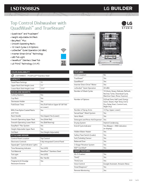
LSDTS9882S B
E
A F I
Top Control Dishwasher with QuadWash™ and TrueSteam®
• QuadWash™ and TrueSteam® • Height Adjustable 3rd Rack • EasyRack™ Plus • Smooth Operating Racks • 10 Wash Cycles & 9 Options • LoDecibel™ Quiet Operation (40 dBA) • Inverter Direct Drive™ Technology • LED Tub Light • NeveRust™ Stainless Steel Tub • LG ThinQ® Technology (Wi-Fi)
9 3/8"
411/16"
(238 mm) (119 mm)
5 1/4" (134 mm)
4 1/2" (115 mm)
2 15/16" (75 mm) 4 3/4" (120 mm)
20 3/16" (512 mm) Water supply hose, drain hose and electric cable should be passed through this area.
海尔 HRO7572-CJ 增压自吸净水机 使用说明书

使用注意事项
尊敬的用户: 您好!为保证使用安全,防止人身伤害及物品损坏,使用本产品前请务必仔细
阅读本说明书并遵守所有安全注意事项。 1. 本产品的安装、维护及保养必须由售后服务网点专业人员进行实施,方可保障产 品正常运行。未经售后服务网点专业人员进行安装、维护及保养,导致机器无法达 到正常状态或性能时,我公司不承担责任。 2. 当遇到停水或管道维修时,请关闭电源和进水三通球阀;恢复供水时,请先打开 其他水龙头排尽泥沙后再打开三通球阀,否则大量泥沙可能导致滤芯堵塞。 3. 如果电源软线损坏,必须用专用软线或从其制造商或维修部买到的专用组件来更换。 4. 反渗透膜的过滤产水流量会受水质、水压和水温的影响。当水质不符合标准、水 压过低、水温小于(25±1)℃时,产水流量将小于标准值。 5. 浓缩水“浓水或废水”可回收利用,不可直接用于饮水,可选择性地用于家庭用 水(浇花等)。(为避免漏水,建议在售后当地网点的指导下进行固定回收管路) 6. 为了保护滤芯,机器长时间待机后会出现短时间冲洗动作,冲洗时会伴随一定噪音, 这个属于正常现象。 7. 测试水效等级时请以关闭纯水出水的方式进行测试(因设计有长时间制水保护功能需 要在4小时内关闭一下水龙头)。 8. 出水龙头关闭后,长时间会流出几滴水,是管路中的尾水积累渗出,是正常现象。 9. 若用户家中未接通自来水,安装本产品时必须使用相配套的过滤自吸头(用户需自行 采购)。
6
安装及维护
② 三通球阀
接其它龙头 或封闭
水管接头
③
①
PE管 (接进水口)
4. 快速接头的安装连接
产品的进、出水口都有快速接头端口。快速接头是一种不需要工具就能实现快速 牢固连接的接头端口。首先拔出端口处U型固定卡环,将端口表面可活动的塑料圈压 向端口,使之与端口相贴就可轻易拔去喇叭型塑料柱塞。将PE管插入接头端口到底, 再向外轻拉一下,使端口表面活动的塑料圈与端口留出一点缝隙,把U型固定卡环插 入缝隙即可。
haier商用机和开水器产品介绍

方案四: 净水器+ 管线机
场所5: 办公场 所
场所6: 房地产
+
方案五: RO+管 线机
9
何为商用净水? 所有居民家用以外的净水设备都 可以叫做商用设备! 具体分:商用净水、商用饮水
10
11
2.海尔商用净水机分析:产品卖点
价位段
40000
30000
25800
29800
20000
15800 13900 9980
3
长春宝钢200G
RO机
4
长春宝钢集团开水平台
5
朝阳区洗手液厂
6
长春铁北酱油厂
7
长春市火车站开水平台
8
1. 海尔商用净水机分析 用户场所
方案一: 商务直饮 机 方案二: 净水器+ 开水器 场所1: 机场、 车站 场所2: 酒店、 餐厅 场所3: 学校、 工厂 场所4: 医院
方案模块
方案三: 开水器 (带超滤)
6、双温度频道,热水、温水可根据需要饮用,温热水龙头可按需定制
3.2.1 海尔开水器产品介绍卖点
型号 额定电压 额定功率 容量 出热水流量(L/H) 进水水源 适用人数 过滤系统 外形尺寸(mm)
HKP023-W 220V~ 3000 26L 30L(热水)/150L(温水) 市政自来水 100 无 890*390*1080
27
3.2.2主销型号简介(8)
型号:HKP032-L 最大优势(1) 采用高效热交换系统,节能环保,省电80%
21
3.1.5 主销型号简介(5)
型号:HKB039-R
最大优势(1) 步进式加热技术,五防安全技术
★ 步进式加热,即开即饮鲜活水
海尔 HRO8H15-2U1 纯水回流净水机 使用说明书
额定总净水量(L)
出水口 1(纯 出水口 2(净 出水口 1(纯 出水口 2(净
水)
水)
水)
水)
HRO8H15-2U1 2
2
4700
5500
额定功率 (W)
85
卫生许可批 准文号
鲁卫水字【2021】第 B038 号
产品尺寸(宽 x 深 x 高)
135mmX395mmX400mm
进水压力 0.1MPa~0.4MPa
数量
注:配件以实物为准。 3.2.2. 环境要求
1. 产品安装处应有市政自来水管路接口,安装水压应为 0.1MPa~0.4MPa,环 境温度应为 4℃~40℃。
2. 应有 220V~电源插座。 3. 产品安装场地干净卫生,周围无污染。
使用钻孔工具时请注意人身安全,并且钻孔位置不能有隐蔽的水、 电、气管线。 3.2.3. 安装方法
会造成机器的损坏或危及使用者的人身安全。 警示: 凡带有该“警示”标志的内容,有关产品安全和使用者的人身安
全,操作必须严格按警示的内容。 注意: 如果操作错误有可能造成物品及财产的损害。
禁止: 避免阳光及户外 避免安装在阳光直射及户外的场所 防冻 请勿将产品储存或暴露在 0℃以下的环境中 受热 禁止在机体附近存放易燃易爆或受热易变形变质物品 排气 禁止堵塞排气口 安装维护 禁止带电操作
2. 有关本产品的水效等级信息,请参考机身“中国水效标识”中的参数内 容。
3. 净水机水效等级说明:对于净水机中的纯水,依据国标 GB 34914-2021 《净水机水效限定值及水效等级》,水效等级分为 3 级,其中 1 级水效最 高。
4. 各等级净水机的净水产水率和标称的额定总净水量应符合下表的规定。
HAPQ产品介绍
1 SET-FREE(mini) 自由设定变频控制商用(家用)多联式空调 系统
2 FSN6Q/FSXNQ 变频控制多联式模块组合中央空调系统
3 节能先锋 4 IVX(mini)
R410A自由设定变频控制多联式空调系统 商用(家用)变频控制多联式空调系统
5 店铺机
店铺用空调系统
6 一拖一
日立商用分体空调
具体型号 RAS-224、280、335FSNMQ
连接内机 RPIZ-FSNQ(S)、RPI-FSNQL/H、 RCI-FSNQ、RCD-FSNQ、 RPK-FSNQ
IVX 系列
IVX HRNMQ系列 制冷剂:R410A 线 体:W5
具体型号 RAS-200、250、300HRNMQ
连接内机 RPIZ-FSNQ(S)、RPI-FSNQL/H、 RCI-FSNQ、RCD-FSN、 RPK-FSNQ
SEF FREE FS5Q系列 制冷剂:R22 线 体:W3
具体型号 RAS-690、840FS5Q
连接内机 RPIZ-FSG1Q、RPIFSG1QL/H、RCI-FSG2Q RCD-FSG1Q、RPK-FSG2Q
FSVGQ系列
FSVGQ系列 制冷剂:R407C 线 体:W5
具体型号 RAS-112/140/160FSVGQ RAS-112/140/160FSYGQ(三相)
产地(HAPQ)
改型版本号 冷媒系统 N—R410A 空—R22 VG—R407C
SET-FREE 多联机系列 标称能力×100W
R22系列
各系列型号说明
R A S– 280 FS 3 Q
冷媒(refrigerant) 空气(air)
系统(system)
产地(HAPQ) 版本号 空—R22
海尔产品简要介绍
BCD-215KC LV;BCD-215KC JV;BCD-215KC ZV;BCD-195KC ZV
容积:137+78;130+65
耗电量:0.39
外性尺寸:620*555*1681;620*555*1556
颜色:蓝色;深绿色;酒红色;酒红色
控温方式:两门机控
全新的时尚外观设计,清爽亮丽
2.VC保鲜为果蔬添加营养新鲜更持久
3.直流全变频技术,静、鲜共享
1.中门10~-18度超宽变温,满足不同的温度需求
2.变频速冻007,可先降至-30度速冻杀菌,无需解冻即时切
3.特设半自动旋转制冰,方便实用
4.LCD竖式液晶触摸屏,操作轻松,状态一目了然
5.冷藏室特设可叠式酒架,是酒类存放的最佳场所
BCD-586WS
容积:400+186
耗电量:1.57
外性尺寸:770*910*1770
颜色:钢制银灰
控温方式:四门对开两抽屉电控
1.顶级法式四门设计,领先全球设计理念
2.全球领先直流全变频技术,体验非凡
3.多路风道\双风幕制冷,多角度立体循环,制冷速度快且均衡,保鲜新典范
1.豪华钢制外观,极富奢华质感
三门电控直流全变频技术压缩机转数在18004350转之间将冰箱内温度波动控制在01度内控温更正确保鲜更持久光波增鲜技术释放五种增鲜光波让您冰箱里蔬菜水果享受阳光浴中门全温区超宽变温技术温度能够在10到18间任意一度调整让新鲜随vc保鲜专利技术释放vc因子既能够增加深冷速冻技术温度可降到30锁住营养不流失2节能系列bcdkabcd72kabcd12ka容积
电脑温控人工智慧
纳米宇航绝热材料节能环保
海尔 HRO10H11-2U1 三屏互联智显净水机 使用说明书
使用说明书型号HRO6H11-2U1HRO8H11-2U1HRO6H99-2U1HRO8H99-2U1HRO10H11-2U1HRO10H99-2U1HRO600CF1-GU1HRO800CF1-GU1HRO1000CF1-GU1智慧净水机智能家电操控智慧场景定制智家商城购物家电报装报修目录使用注意事项 (1).注意事项 (1).装箱清单 (2)产品简介 (3).技术数据 (3).产品部件名称 (3).工作原理图 (4).电气原理图 (4).产品特点 (5).产品功能 (5)安装及维护 (6).安装方法 (6)使用指南 (9).使用方法 (9).显示功能说明 (9).滤芯更换周期 (11).滤芯更换 (11).海尔智家APP联网指引 (13)故障诊断及排除 (14)环保清单 (16).产品中限用物质的名称及含量 (16)产品中与水接触材料列表 (16)保修服务 (17).用户须知 (17).保修说明 (17).温馨提示 (17)“1+5”成套服务 (18)尊敬的用户:您好!为保证使用安全,防止人身伤害及物品损坏,使用本产品前请务必仔细阅读本说明书并遵守所有安全注意事项。
1. 本产品的安装、维护及保养必须由售后服务网点专业人员进行实施,方可保障产品正常运行。
未经售后服务网点专业人员进行安装、维护及保养,导致机器无法达到正常状态或性能时,我公司不承担责任。
2. 当遇到停水或管道维修时,请关闭电源和进水三通球阀;恢复供水时,请先打开其他水龙头排尽泥沙后再打开三通球阀,否则大量泥沙可能导致滤芯堵塞。
3. 如果电源软线损坏,必须用专用软线或从其制造商或维修部买到的专用组件来更换。
4. 反渗透膜的过滤产水流量会受水质、水压和水温的影响。
当水质不符合标准、水压过低、水温小于(25±1)℃时,产水流量将小于标准值。
5. 浓缩水“浓水或废水”可回收利用,不可直接用于饮水,可选择性地用于家庭用水(浇花等)。
水源多联机空调系统
四、水冷多联机空调系统 4.1、水冷多联机的原理
水冷多联机和风冷多联机的制冷(热)循环原理完全相同,而
最主要的区别就是室外机的换热介质的不同。水冷多联空调系统运 行时,与室外机进行换热的介质是水,而不同于传统的风冷多联机 其室外机的换热介质为空气。室外换热器的结构形式也有所不同, 风冷多联机为强迫对流风冷换热器,而水冷多联机为套管式水冷换 热器,由于水冷换热器的换热系数远大于风冷换热器,交换相同的 热量,水冷换热器换热面积大大减少。因此,水冷多联机的室外机 体积相对较小,可方便地安装在建筑物任何地方,而不像传统的风
系统可以回收建筑物内部余热,将内部热量转移到需要制热的周边区, 从而降低冬季辅助加热费用。
4、节省内外机连接铜管,减少制冷剂充注量。由于水环路的引入,
使多联机主机不必集中放置在楼顶,而可以放在每一层楼中的小房间 里(或吊顶内),这样就大大降低了制冷剂环路的长度,节省了昂贵
的铜管使用量,对系统能效比影响更小,同时减少了制冷剂充注量。
8-48HP发展到了5-56HP 。 而多联机冷媒的使用方面,原来的变频多联
机大部分使用的为R22冷媒,部分使用R407C冷媒,06/07年开始,企业多 开始倾向于向R410A新型环保冷媒发展,以有效地减少对大气臭氧层的破 坏。
三、多联机分类
1、按外机冷却形式分类 主要有风冷多联机和水冷多联机两种。
多联机与水源热泵或水环热泵相结合的一种空调系统,它不仅继承了
风冷多联机的所有优点,还能弥补风冷多联机的众多缺陷,是一种非 常有前景的新型多联空调系统。
3.2.1、变频多联机概述 变频多联机系统是“变频一拖多可变冷媒流量中央空调系统”的
简
称,是由一台室外机和若干台室内机组成的一个冷媒循环系统。该系 统由制冷剂管路连接的室外机和室内机组成,室外机由室外侧换热器 、压缩机和其它制冷附件组成;室内机由风机和直接蒸发器等组成。 一台室外机通过管路能够向若干个室内机输送制冷剂液体,通过控制
- 1、下载文档前请自行甄别文档内容的完整性,平台不提供额外的编辑、内容补充、找答案等附加服务。
- 2、"仅部分预览"的文档,不可在线预览部分如存在完整性等问题,可反馈申请退款(可完整预览的文档不适用该条件!)。
- 3、如文档侵犯您的权益,请联系客服反馈,我们会尽快为您处理(人工客服工作时间:9:00-18:30)。
采用毛细管与电磁阀组 合的回油设计,压缩机 低频运转时使用毛细管 回油,降低能量损失, 压缩机高频时采用毛细 管+电磁阀回油,确保 压缩机储油量。
四、稳定可靠
3.业界独有的油温、排气双重温度控制
注:每台压缩机均设有油温传感器和排气温度传感器,精确检测压缩机的排 气温度和油温,避免压缩机油因碳化或稀释严重造成压缩机不良的问题发 生。
★底层采用485协议,布线简单,用户投入少 ★图形化人机界面,操作简单,方便用户以不同的方式进行管理 ★对外接口有modbus rtu,modbus ip和BACnet ip等,方便接入楼宇控制系统。
五、安装使用便利
4.智能监测,安装、维修便捷
五、安装使用便利
5.多种控制模式可选择,使用灵活
29
31
六、健康舒适
---室外机
3.influence 运行效果不受极端天气影响 No from ambient temperature
循环水获取冷热源,极端天气对制冷、制热效果没有影响。 特别是制热工况,不需要除霜,室内温度波动范围在±0.5℃。
32
六、健康舒适
超薄型风管机
---室内机
薄:185mm超薄机身,吊顶不压抑 静:18分贝超静音运转,舒适宁静 智:标配智能wifi,省心便捷(家中机、变频一拖一标配) 恒温除湿:除湿不降温,远离空调病(H机型专享)
四、稳定可靠---样板工程
项目简介:
地理位置:巴基斯坦人马座项目由阿联酋和巴基斯坦联合投资4亿美元历时5年建成,位于首都
伊斯兰堡; 建筑类型:3栋独立式建筑,玻璃幕墙造型; 设备选择:第一栋楼选择了顶出风多联机,第二栋楼选择了侧出风多联机;由于建筑形式导致
前两栋楼实际效果未达到预期,所以第三栋楼安装了Haier水源多联中央空调。
注:以上保护控制需在机组上电时有效。
四、稳定可靠---样板工程
顶 出 风
侧 出 风 水 源 多 联
项目名称:巴基斯坦人马座
类型: 商场、公寓、办公、酒店 安装时间 : 2014 产品系列:MX6顶出风,侧出风,水源多联机
项目规模:2000HP
四、稳定可靠---样板工程
项目简介:
地理位置:阿尔及利亚Bahia Center Mobilart城市综合体项目位于位于阿尔及利亚第二大城市奥 兰的海滨商业区; 建筑类型:由四栋31层的高层建筑构成,含商场、酒店(500间)以及高端住宅,是奥兰海滨著 名的地标性建筑; 设备选择:考虑到高层建筑的特点工程主体外机分别采用了海尔测出风多联机、水源多联机,内 机选用了低静压、高静压风管机;
COP
7 6 5 4 3 2 1 0 8HP 10HP 12HP 6.02 5.43 4.81
EER 5
4.98 4.67 4.35
4.8
4.6 4.4
4.2
4 8HP 10HP 12HP
注: EER测试条件:室内温度:27℃DB,19℃WB,室外温度:35℃DB,水源侧:进水温度30℃,单位名义制冷量流量 0.215m3/(h.Kw),等效管长:7.5m,高低差:0m。 COP测试条件:室内温度:20℃DB,14.5℃WB,室外温度:7℃DB,水源侧:进水温度20℃,单位名义制冷量流量 0.215m3/(h.Kw),等效管长:7.5m,高低差:0m。
0.745㎡
990mm
545 mm
0.42㎡
775mm
占地面积减少 43%
24
五、安装使用便利
3.多种控制器可供选择
遥控: 线控:
YR-H005
YR-E17
一个线控器最多控制16台内机
集中控制:
YCZ-A004
IGU05
一个集中控制器最多可以连接32 套系统,最多控制128台内机。
五、安装使用便利
特定螺纹套管换热器,最小传热温差低至1℃以下。套管换热器整体保温设计,热量损失更小。
双电子膨胀阀两流路独立控制设计,流量调节精度更高, 部分负荷运转时换热面积可进行调整。
三、节能环保
4.采用两级深度过冷控制技术
1st 换热套管的自过冷控制
2nd 高效率板式换热器的应用
通过深度过冷, 过冷度最高达到 30℃,换热能力提 高 46% ,冷媒侧压力损失减少 55%, 可以提高系统能效 9%
四、稳定可靠
4.低压损高效油分离器设计
压缩机排气
四、稳定可靠
5.双压力传感器设计,全面探测系统冷媒状态,机组运行更稳定
四、稳定可靠
6.海尔特有的防冻管保护技术,确保机组不被冻坏
同轴螺纹套管换热器设计,防冻能力强;
水系统靶流、出水水温保护控制; 氟系统低压压力进行保护控制; 进出水温、压机频率、循环水流量等参数动态适配控制技术; 冬季待机时自动防冻运转控制。
3.多种控制器可供选择
YCZ-A004+IGU05
•集中控制器,最多可控制128台室内机
•7吋彩色触摸电容屏
•周定时 •区域设置和控制,可以设定几台内机为一个区域,进行集中控制 •节能设置,集中设定温度的限制,室内空调不能单独设定
五、安装使用便利
3.多种控制器可供选择
第二代Hcm-02空调管理系统
运行状况:全年运行,运行状况良好
22
CAC Product Planning
2013-09-09
五、安装使用便利
1.内外机长配管、高落差连接
冷源
Max.300m 最长配管 Max.50m
落差 ID/OD
Max.200m 冷却水管
Max.1.96 MPa 水路压力
Max.150(120)m 单程配管长度
12
三、节能环保
7.机组采用R410A环保制冷剂,零部件按欧盟标准设计
R410A环保冷媒的ODP为0,所有零部件严格按Rohs指令标准设计 采用R410A 环保冷媒
不含破坏臭氧 层的氯元素 对人体无任何 不良影响
直流变频 技术
实现高效率,保 证节能化
冷媒用量减少
◇废弃时冷媒向大气的排出量减少
◇使用时冷媒向大气的排出量减少
一、系列全
2.室内机系列
• 水源多联机室内机和风冷多联内机通用,内机的安装和风冷机型一样。
水源多联系列室内机系列
超薄型风 管机
低静压风 管机
中静压风 管机
高静压风管 机A系列
两面出风嵌 入机
四面出风嵌 入机
独立出风嵌 入机
吊落机
壁挂机
新风机
18-71
直流/交流 可选
18-140
22-160
56-280
海尔水源多联机系列推介资料
2017-03
1
系列全
健康舒适
适用范围广 安装 使用便利
节能环保
稳定可靠
一、系列全
水源多联室外机系列
8-12HP
16-24HP
26-36HP
模块组合表
序号 1 2 3 4 5 6 7 8 9 10 11 3 额定输出 16 HP 18 HP 20 HP 22 HP 24 HP 26 HP 28 HP 30 HP 32 HP 34 HP 36 HP 室外机组合 8HP 2 1 10HP 1 2 1 1 2 3 2 1 12HP 最多可连接室内机 台数 23 29 33 36 39 43 46 50 53 56 59
60 ~75 dB(A)
街道
螺杆机组 70~ 90dB(A)
工厂
居住房间
30
六、健康舒适
---室外机
2.模块散热采用独有的冷媒冷却,运行稳定、噪音低 Chilled electric control module
采用海尔独有的冷媒冷却技术,减少室外温度对模块出力的影响 相对风冷机型,箱体散热减少了一个散热风扇,噪音降低3dB(A)Βιβλιοθήκη 22-7122-140
22-160
直流/交流 可选
22-140
22-71
160-600
二、适用范围广
1.水源温度、流量范围大
50℃ 45℃ 40℃ 35℃ 30℃ 25℃ 20℃ 15℃ 10℃ 5℃ 0℃
45℃
制热进水水温运行范围 7~45℃ 制冷进水水温运行范围
45℃
5~45℃ 室内温度运行范围 7℃
Φ 19.05 Φ 9.52 Φ 9.52 50
Φ 25.4 Φ 12.7 Φ 9.52 53
※1 室内温度:27℃DB,19℃WB,室外温度:35℃DB,水源侧:进水温度30℃,单位名义制冷量流量0.215m3/ (h.Kw),等效管长:7.5m,高低差:0m。 ※2 室内温度:20℃DB,14.5℃WB,室外温度:7℃DB,水源侧:进水温度20℃,单位名义制冷量流量0.215m3/ (h.Kw),等效管长:7.5m,高低差:0m。 注:产品性能执行标准:国际标准《GB/T 18837-2002多联式空调(热泵)机组》、 欧盟标准《EN 14511-2011 Air conditioners, liquid chilling packages and heat pumps with electrically driven compressors for space heating and cooling》 4
运行情况:全年运行,运行状况良好
四、稳定可靠---样板工程
项目名称:Bahia Center Mobilart
类型:城市综合体:商场、酒店、住宅 安装时间 : 2013-2014 产品系列:侧出风多联机,水源多联机 项目规模:1000HP
21
CAC Product Planning
2013-09-09
六、健康舒适
Low noise level 1.双级噪音隔离技术
---室外机