5600ST时间型软化阀操作手册Service Manual
软水器使用说明书
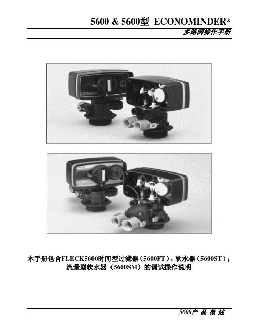
5600 & 5600型ECONOMINDER®多路阀操作手册本手册包含FLECK5600时间型过滤器(5600FT),软水器(5600ST);流量型软水器(5600SM)的调试操作说明FLECK全自动控制器以闻名于世的FLECK公司软化水技术为基础,它是将软水器的运行及再生的每一个步骤实现全自动控制,并采用时间、流量或感应器等方式来启动再生。
由于FLECK系列全自动软水设备控制系统技术成熟、操作简便、富来控制器采用的工程塑料和无铅黄铜阀体完全符合食品卫生要求,配以聚四氟乙烯(Teflon)涂层,活塞减小了阻力,延长了使用寿命,运行可靠。
FLECK系列全自动软水器可用于家用、工业锅炉、热交换器、宾馆饭店、食品工业、洗衣印染、医疗卫生等行业,该产品具有自动化程度高、交换容量大、结构紧凑、能耗低、省人工、无需日常保养等特点。
系统技术参数进口压力:0.2 Mpa-0.6 Mpa工作温度:2 ℃—50℃进水硬度:符合国家标准出水硬度:≤0.03mmol/L使用电源:220v/50Hz AC布置形式:单罐或双罐串联(二级软化时采用)再生方式:顺流再生操作程序:自动程序控制使用树脂:001×7强酸性阳离子交换树脂我公司将为用户提供完善的技术服务及售后服务。
第1页5600ST安装和启动程序软水器的安装,应根据制造商建议的入水口、出水口和排污口接管,且应符合相关管路规范。
在软水装置接通电源前1.将软水器控制阀手动转至工作位置,打开进出水口,使水流入树脂罐。
直到管路内空气排尽,当水流流出出水口时,关闭进出水口。
注:可手动旋转控制阀前部的旋钮将其拨至不同的再生位置,直到显示软水器处于所需位置。
2.将控制阀手动转至反洗位置,使水经排水口流出3或4分钟。
3.取下控制阀后盖板。
4.确保盐的用量按制造商的建议设置。
如有必要,按设置说明书设置盐的用量。
将控制阀手动转至盐水重注位置,使水填充至空气止回阀顶。
5600 5600 Econominder 用户手册说明书

For questions or in case of emergency, please call your local service technician (preferably the one whoinstalled the system).IMPORTANT: The information, specifications and illustrations in this manual are based on the latest information available at the time of printing. The manufacturer reserves the right to make changes at any time without notice.Setting the Time of Day:To set the time of day, push the red button and spin the 24-hour gear until the present time of day is visible above the time of day arrow.Forcing a Manual Regeneration:To manually regenerate the valve, turn the manual regeneration knob clockwise until it reads“REGEN.”5600 ModelSetting the Time of Day:To set the time of day, push the red button and spin the 24-hour gear until the present time of day is visible above the time of day arrow.Setting the Program Wheel:To set the program wheel, lift the “people” dial and rotate it so that the number of people in the household is aligned with the household grains per gallon water hardness. Release the dial and check for firm alignment at the setting. This provides reserve capacity based on 75 gallons per person.Forcing a Manual Regeneration:To manually regenerate valve, turn the manual regeneration knob clockwise until it reads “REGEN.”NOTE: Unit will regenerate tonight when the gallon capacity reaches zero.5600 Econominder Model Setting Time of Day & Initiating a Manual RegenerationService:Hard water enters unit at valve inlet and flows down through the mineral in the mineral tank. Conditioned water enters center tube through the bottom distributor, then flows up through the center tube, around the piston, and out the outlet of the valve.Preliminary Rinse:Slow rinse of the resin bed. Water flows down through the resin bed up the bottom distributor and out the drain.Backwash:Hard water enters unit at valve inlet, flows through piston, down center tube, through bottom distributor, and up through the mineral, around the piston and out the drain line.Water is passed through the resin bed in the opposite direction of normal flow, which flushes suspended matter out of the resin tank. Backwashing also loosens the resin bed which becomes compacted during the softening (in service) cycle.Brine/Slow Rinse (Softener Only):Hard water enters unit at valve inlet, flows up into injector housing and down through nozzle and throat to draw brine from the brine tank, brine flows down through mineral and enters the center tube through bottom distributor and out through the drain line.The resin beads are washed with the strongsolution of salt water which is called the brinesolution. Since the resin beads prefer calciumand magnesium ions, the slow rinse allowsan overwhelming concentration of sodiumions to overpower and force the calcium andmagnesium ions off of the resin beads and arethen discharged down the drain.Rapid Rinse:The resin bed is rinsed to remove excess brinesolution from the tank and the resin beads arethen ready to produce soft water again.Hard water enters unit at valve inlet, flowsthrough piston, down center tube, throughbottom distributor, and up through the mineral,around the piston and out the drain line.Settling Rinse:Slow rinse of the resin bed. Water flows downthrough the resin bed up the bottom distributorand out the drain.Brine Tank Refill (Softener Only):Hard water enters unit at valve inlet, flows up through the injector housing, through the brine valve to refill the brine tank. Valve is now delivering soft water to the home. Raw water is refilling the brine tank to make a brine solution for the next regeneration.Regeneration:When the valve is in Regeneration, raw water is being passed to service until rapid rinse is complete.Descriptions of Softener & Filter Control Valve PositionsProblemSolution Control valve fails to regenerate Check for power outage and verify unit is plugged in.If this does not work, contact your local water servicetechnician (preferably the one who installed the system).Water does not feel or appear softCheck salt level in brine tank & maintain salt level abovewater level. If problem still exists, contact your localwater service technician.Unit uses too much saltContact your local water service technician.Loss of water pressureIron in conditioned waterExcessive water in brine tankOther problems with the watersoftenerPower Outage Reset the Time of Day in the event of a power outage/failure. See “Setting the Time of Day” page.Adding Salt Ensure that the salt level in the brine tank is always above the water line.Water Pressure Water pressure range of 20-125 psi is required for regeneration valve to operate effectively.Electrical FacilitiesAn uninterrupted alternating current (A/C) supply is required. Please make sure voltage supply is compatible with unit before installation.Existing PlumbingCondition of existing plumbing should be free from lime and iron buildup. Replace piping that has heavy lime and/or iron build-up. If piping is clogged with iron, install a separate iron filter unit ahead of the water softener.Location of Softener, Drain & Brine Tank Locate the softener close to a clean working drain and connect according to local plumbing codes. The brine tank should be located within 20 feet of the water softener. Drain cannot be elevated more than 36 inches or exceed 20 feet in length.Bypass Valves Always provide for the installation of a bypass valve if unit is not equipped with one. If valve is leak-ing, turn bypass from In Service to the Bypass Position.NOTE: If the valve continues to leak after turning the bypass to bypass position, shut off the main water line and call your local service technician (preferably the one who installed the system) IMMEDIATELY.General Residential Checklist & Troubleshooting5600 L-Style Econominder 5600 L-Style EconominderTo download the service manual for this valve, please visit:。
富莱克软化水控制阀技术参数总结

富莱克软化水控制阀技术参数总结软化水控制阀,是软化水设备中必不可少的配件。
富莱克软化水控制阀并不能适用所有的情况,但也可以共同构建增强性能、降低成本的最佳解决方案。
富莱克软化水控制阀不同型号技术参数1、富莱克FLECK2850软水器技术参数软水器控制方式,时间(T),流量(M),电子控制(NT)。
应用范围,软化(S),过滤(F)。
软水器型号,2850ST,28500SM,2850NT,2850FT。
多阀系统,系统6(双阀同时工作)NT系统6(双阀同时工作)。
进出水管径, DN40。
单阀理论设计最大出水量,11.5M3/Hr。
2、富莱克FLECK2900软水器技术参数控制方式,时间控制型(T),流量控制型(M)电子控制型(NT)。
应用,软化(S),过滤(F)。
软水器型号,2900ST,2900SM,2900NT, 2900FT。
多阀系统,系统6(双阀同时工作), 系统7(双阀一用一备)NT系统6,7。
进出水管径, DN50。
单阀理论设计最大出水量,24.0M3/Hr。
3、富莱克FLECK3900软水器技术参数软水器控制方式,时间控制型(T),流量控制型(M)电子控制型(NT)。
应用,软化(S),过滤(F)。
型号,3900ST,3900SM,3900NT, 3900FT。
多阀系统,系统6(双阀同时工作), 系统7(双阀同时工作)NT系统6,7。
进出水管径, DN80。
单阀理论设计最大出水量,56.8M3/Hr。
4、富莱克FLECK9000软水器技术参数富莱克FLECK9000软水器控制方式,流量(M),电子控制(SE)。
应用,软化(S)。
型号,9000SM, 9000SE。
进出水管径, DN20,DN25。
最大设计出水量,4.7M3/Hr。
富莱克FLECK9500软水器技术参数。
控制方式,流量控制型(M),电子控制型(SE)。
应用,软化水(S)。
型号,9500SM, 9500SE。
进出水管径, DN40。
软化水多路阀说明书

USE AND MAINTENANCE MANUALV360Document Revision Revisionnote Date MAN0031 A DraftINDEXGENERAL CHARACTERISTICS – TECHNICAL SPECIFICATIONS 4COUNTERCURRENT AND FAST RINSE LOADS 5DIMENSIONS 6DIAGRAMS 7-9 FUNCTIONALFUNCTIONAL DIAGRAMS (with countercurrent flow regulator) 10 VARIATIONS 11-13USESPECIFICATIONS14 USE15-18 CONNECTIONSVALVE/TIMERTABLES 19 INJECTORFLOW CONTROL PREVIEW V360 20TIMER CHOICE TABLE 21BASIC VALVE COMPONENTS SOFTENING AND DEMINERAL. 22BASIC STANDARD FILTER COMPONENTS 23OPERATIONS 24 MAINTENANCENORMALGENERAL CHARACTERISTICS – TECHNICAL SPECIFICATIONSThe “360” valves represent an essential element for the realisation of systems of various types and for various uses.Softening – single, duplex, or on more columns for domestic industrial or laboratory use.Demineralisation and decarbonisation – single, duplex, for laboratory and industrial use and for all uses which require water with guaranteed quality characteristics.Filtration – single or duplex for all applications shown above.The valves are made from materials which guarantee the maximum durability and quality.The valves are available with a wide range of timers, for the control of all operative phases of service and regeneration, from the simplest electromechanical timer with a weekly timer, to the sophisticated electronic timers in various models which allow for volume and volume/time controls, controls of salinity in microsiemens/cm etc.With the electronic systems, all the times of the operative phase operations are programmable, relative to the type and dimensions of the system.For the specific characteristics of the timers, see the relevant manual.TECHNICAL SPECIFICATIONSRunning pressure : 2 - 6 barMax. Running load : 45m3/hFor variables of the value see graph : -Countercurrent rinse load : max. 12 m3/hEquicurrent fast rinse load : 480-1300 l/hEquicurrent fast rinse load : max. 18 m3/hStatic resistance to pressure : 22 barMax quantity regenerable resin : 1200 l.Running temperature : 5 - 40° cBasic materials of principal components : abs + fvEntry/exit attachments : 2” female gasCOUNTERCURRENT LOAD GRAPHFAST RINSE LOAD GRAPHDIMENSIONS6 Exit1 Connection for cylinder openingTop column7 Connection top column2 Connection for cylinder closureTop column3 Connection for cylinder opening8 Connection bottom columnbottom column9 Connection for suction Ø 1”4 Connection for cylinder closurebottom column5 Entry 10 Connection for male drain Ø ISO 40 11 Connection for pilot timer control364-A 1” ½ GAS364-B 2” GAS364-C 2” ½ GAS364-D 3” GAS364-E01 ISO 50 GLUED364-F01 ISO 63 GLUED364-G01 ISO 75 GLUED364-N01Ø 60.4 GLUED364-P01 3” NPT GLUEDFUNCTIONAL DIAGRAMSFUNCTIONAL DIAGRAMSFUNCTIONAL DIAGRAMSS.I.A.T.A. S.r.l Società Italiana apparecchiature trattamento acqua MAN0031 BOZZA Pag. 10 ofFUNCTIONAL DIAGRAMSVARIATIONS FOR SINGLE SYSTEMS USEVARIATIONS FOR DUPLEX SYSTEMS USEVARIATIONS FORDEMINERALISATION AND FILTRATION SYSTEMS USEUSE SPECIFICATIONSReferring to the paragraph VERSIONS seen above, the various possibilities for the uses of this valve in the various applications may be examined.1) Single softening: the system consists of a basic valve V360A-05/05 with or without bypass,and a timer complete with a minimum of 2 external pilots in different solutions, with which the system may be personalised as desired.In particular, varying the number of external pilots, it is possible to obtain the following personalisations:I. 2 pilots controls only the movement of the pistons of the valveII. 3 pilots controls also an additional use closure valveIII. 4 pilots controls a use closure + a suction closure2) duplex softening: the system is made on two columns, each of which is run by a V360A-05/05 valve. This is controlled, with water or air, by a timer with a minimum of 2 pilots per valve. The alternating duplex systems (one column is in service while the other is in regeneration or not in use), may be controlled by the AQUA CUBIC timer, which may be supplied in two standard versions:pilots(AC5-02/05), run by volume. The system allows for use of two brineI. 5valves plus a use closure valveII. As a variation on this system, it is possible to substitute the two brine valveswith two on-off hidro-pneumatic valves for the closing/opening of the suctionduct(see valve V1 page 10), using an AQUA CUBIC 7-pilot timer. (AC7-02/05)3) Demineralisation and Decarbonisation: this is the applicative sector in which the characteristics of the V360 valve may be best appreciated in the models V360D-04/05 & V360D-05/05. The timer predisposed for demineralisation is electronic with external pilots, capable of controlling an anionic and cationic column, can control the level of conductibility showing a valve in µsiemens/cm at the exit of the system, and regenerate the system automatically. The number of pilots of the timer is determined by the type of system requiredI. AQUA IONIC 5 pilots ( AI5-02/05 ) controls the two columns + an on-off hydro-pneumatic use closure valveII. AQUA IONIC 7 pilots ( AI7-02/05 ) controls the two columns+ an on-off hydro-pneumatic use closure valve+ two on-off hydro-pneumatic valves for theclosing/opening of the regenerator suction.4) Filtration: the considerations made regarding softening are valid both for single and duplex systems, with the exception that in this case the suction of the regenerator does not need to be controlled.. For further details regarding the timers, see the table of timer choice (page 23).VALVE/TIMER CONNECTIONSVALVE/ TIMER CONNECTIONSVALVE / TIMER CONNECTIONSVALVE / TIMER CONNECTIONSINJECTOR TABLES V360FLOW CONTROL V360PREVIEWTIMERBASIC COMPONENTS FOR V360 SOFTENING AND DEMINERALISATIONBASIC COMPONENTS V360 FILTRATIONSPARE PARTSPOS. CODE DESCRIPTION1 362-L V360 A/C MACHINED BODY2 361-L V360 B/C MACHINED BODY3 1958 PISTON V360 LONG ASSEMBLED1958-C PISTON V360 SHORT ASSEMBLED4 2235 PISTONS AND LINING V360 SPARE PARTS KIT2235-F PISTONS AND LINING V360 FILTER SPARE PARTS KIT 5 2236-B V360 COMPLETE WHITE INJECTOR KIT2236-R V360 COMPLETE RED INJECTOR KIT2236-N V360 COMPLETE BLACK INJECTOR KIT6 1955 STOPPER V360 ASSEMBLEDNORMAL MAINTENANCE OPERATIONSProblem CauseCorrective action1) Drain leaking while in service or on stand-byPilot leakage Disconnect alternately connections 2 and 4, see page 15.If water is leaking from one of the two pressure connections, this means that the relative pilot has leaks and should be replaced.If the leakage does not come from the pilot, the cause should be sought, possibly originating from the head of the V360 piston.Valve leakage through the piston system1. Disconnect one by one the connections 1 and 3, see page 15, if the leaking stops, inspect and if necessary replace the OR of the plastic screw or the piston if it is ridged2. Check that the pistons and following Or are undamaged and replace them: a) First OR after the plastic screw for A/C pos. 3 b) Second OR after the plastic screw for B/C pos. 52) Assembly and disassembly of 2 chambers Check the internal surfaces of the chambers For all the operations regarding the inside of chambers A/C and B/C the following procedure should be respected: A. Turn off the entry waterB. Disconnect the control pipes of the piston movementC. Remove the seeger ring from the stopper, using a suitable toolD. Remove the stopper or the relative ORE. Extract the piston pressing on the internal pin; if it is difficult to extract, loosen theback flange, to allow air to enter without depressing the piston chamber F. Remove the ring-nut holding seeger ringG. Remove the plastic screw and the whole set of distancers and Ors taking care toreinsert them in the upended piston so as not to lose the correct consequence H. Check that the inside of the chamber is undamagedI. Reassemble everything, paying attention to the following:1) Check that the piston is not scratched and above all that the two DE of the head areundamaged and positioned correctly (not upended) see PART. 12) Check that the two seeger rings are not too out of the shape and when theseeger is reinserted check that the tool used to insert the seeger is used to support the expansion of the ring into its position. The seeger stopper should be replaced every time maintenance is carried out.See page 22Hardness leak at exit Probable leak between entry and exit or on ac/bc seal Take the piston out of the entry, checking that there is no damage to the surface. If the piston is damaged, replace it. Otherwise, replace the Ors (pos. 1 and pos. 2) of theentry chamber. To carry out this operation, proceed as indicated in point 2, paragraphs “a,b,c,d,e,f”.Suction failure Injector Disconnect the injector pipe between the injector and the brine. In case of air suction,the reason of a suction failure have to be searched in the measurement system of the brine valve.In case the injector does not suck verify if:(a) The filter inside the injector body is obstructed(b) The internal OR are defective or the two injector body are defective (in that casewe suggest to contact SIATA)(c) The drain conditions do not match with the choosen injector。
软化水操作说明书、手册
软化系统操作说明书(公司LOGO/图片)×××公司××年××月××日第一篇触摸屏操作说明一、系统简介本套系统是××公司专门为××行业软化用水而设计,采用气动阀通过PLC编程自动控制,根据在线流量计设定累积流量实现软化系统运行的自动化操作,系统可自动再生、反洗。
该套系统具有良好的适应性、可靠性和经济性,适用于用水量不大的软化系统。
二、系统配置2.1、系统流程图2.2系统主要配置清单序号名称规格/型号材质数量生产厂家1全自动控制器FLECK3900//套美国弗莱克2软化罐/玻璃钢/只3树脂/阳离子树脂/淄博东大4盐液泵/氟塑料/台安徽茂源5盐液计量箱/PE/只6袋式过滤器/304/台7阀门/304/PVC/批8管路管件/304/PVC/镀锌/批9流量计全自动控制器配套/台10电控箱///台11控制系统///套2.3技术要求入口压力:0.3~0.4MPa;进水水质要求:符合国家自来水标准;产水硬度:≤0.03mmol/L德国度;产水量:35T/hr,一用一备。
三、操作步骤3.1系统操作3.1.1准备1、打开软化罐体手动进出水阀,保持袋式过滤器进出口阀门以及软化供水泵进出口阀门处于开启状态(若水源切换到RO水时,还需将供水泵后软化系统总的进水阀门打开)。
2、将盐路手动阀门(排污阀,清洗阀除外)全部处于开启状态。
3、在盐池内加入足量的颗粒盐。
4、送上总电源。
该系统采用PLC+触摸屏控制,除溶盐加盐系统外机组可自动运行。
3.1.2触摸屏控制进入机组上电后,将自动进入欢迎界面,点击PLC触摸屏上面的进入操作,如图1,操作人员输入用户名:管理员用户名admin;密码:000,点击确定后自动进入工艺流程画面。
密码是否设定可根据客户自行选择(触摸屏图片)图13.1.3工艺流程画面在欢迎界面成功输入密码或点击“流程画面”,在该界面下能观察各个阀门、泵的开启,盐池、盐箱液位以及系统运行状态。
5600控制器使用说明书

安装1、安装的一般要求①、进水压力应在0.2-0.5MPa,当水源压力无法满足要求时,可安装增压水泵提高进水压力。
如果压力过高,应安装减压阀来控制进水压力。
②、进水温度应在5-45℃之间,电源采用交流200V/50Hz。
③、软水器应安装在牢固的平台上,附近有畅通的下水,并留有足够的操作和维修空间。
④、工作环境温度应在5-50℃之间,相对湿度≤95%(5℃时)。
2、控制阀的安装与树脂填装(顶装形式)第一步:首先将下布水器牢固安装在中心管底端,然后插入到树脂罐中央,在中心管上端低于罐口0.5mm处截断并导角,然后用胶带封住中心管口,以防树脂漏入。
第二步:将石英砂沿中心管周围空隙投入树脂罐,并使之在罐底铺平,石英砂高于下布水器上20mm,石英砂应按粒径级别分层铺装,主要起到布水作用(对于直径小于500mm树脂罐一般不装石英砂)。
第三步:将树脂均匀地装入树脂罐中,装至规定的层高后,再向注入10%的食盐溶液,至浸没树脂为止,使树脂充分膨胀。
树脂装填完,应取下中心管的封口胶带,上述操作时应注意使中心管始终保持在树脂罐口的中央位置。
第四步:将上布水器安装到控制阀上,然后将中心管从上布水器内插入到控制阀内,小心地沿顺时针方向转动控制阀,直至旋紧在树脂罐接口上(或用法兰连接固定)。
注意上布水器与控制阀、中心管,下布水器与中心管必须严密,防止树脂跑出。
中心管与控制阀必须严密不漏水,否则会出现窜硬水现象。
3、管道连接要求①、与软水器连接的管道应采用给水塑料管,排水管不得采用软塑料管,防止管道变形,影响排水效果。
②、按照控制阀进出水箭头标记连接进出水管,采用流量型再生控制器,流量计必须安装在出水口。
③、进出水管应装有压力表及手动阀门,同时还应装有旁通阀,在出水管阀前还应安装有取样阀。
进水管阀后一般安装有 Y 型过滤器,防止管道内污物堵塞阀体造成设备无法正常运行。
④、排水管的连接长度不应超过6m,尽量减少弯度,并严禁安装阀门。
5600中文调试说明书

5600调试说明书1Dial Selection数字面表显示数字面表显示,批处理百分比显示。
2Power Connection供电5600可以接直流或交流24V供电,不要将220V接入设备,会烧坏设备,为了减少电流噪声的影响,电源供电线和数据线要独立走线。
具体连接请按英文说明书第一页第二个图连接3Compatible Sensor Wiring探头的连接我公司的流量探头有两种输出信号:一种为正弦信号(如 515,525,2517等),另一种为方波信号(2000,2507等),探头的连接请按英文说明书第一页第三个图连接。
为了减少电流噪声的影响,电源供电线和数据线要独立走线。
4Batch Contact Wiring 批处理连接(5600与电磁阀的连接)连在背面板上的Batch端,它就相当于一个开关,具体连接请按英文说明书第一页第四个图连接。
5Remote Control Wiring 远程控制开关实现远程控制功能,与背面板的Remote的连接,远程连线最大不要超过30米,具体连接请按英文说明书第二页第一个图连接6End of Batch/Counter Pulse Output Wiring批处理和计数连接实现脉冲计数功能,与背面板的CNT/EOB Output连接,具体连接请按英文说明书第二页第二个图连接。
图A表示计数器的连接;图B表示二个5600的连接(即End of Batch功能)7Option Contact Wiring OptionsOption Contact相当于另一个控制开关,A图表示Two Stage Shutdown (两个阀门比较功能),图在第二页的7AB 图表示无流量告警信号或过流告警信号的接法,图在第二页的7B8Current Output Wiring OptionsA图表示4~20mA的接法,建议还要接一个保险,在第二页的8AB图表示电动阀的接法,在第二页的8B调表步骤:进入菜单:因为要按ENTER键,所以不要在5600的第一个显示项中进入校准菜单,在后面几个显示菜单中再按下面步骤进入Cal和Options菜单STEP 1按住ENTER键:2秒后进入校准程序(CAL),5秒后进入选项程序(OPTIONS) STEP 2密码为 (上上上下),在输入密码后,显示第一个选择项STEP 3用上下键选择菜单STEP 4按右键来选择需要的项目,被修改的项目会闪烁STEP 5对闪烁的项目按上,下键来修改此项目,按右键选择旁边需修改的项目STEP 6按ENTER键储存修改后会自动返回STEP3STEP 7同时按下上下键返回正常状态.一 AUTO CAL的使用使用AUTO CAL时,要确定流出液体的体积(可用灌或桶),由于AUTO CAL 要计算时间,所以泵和AUTO CAL要同时开动或停止,这样计出来的时间会较准,操作过程为在Auto Calibrate <Enter> to Start 菜单下,按下Enter,开始计时,在Auto Calibrate <Enter> to Stop菜单下,按下Enter,停止计时,在Volume 菜单中,输入测量值。
5600水处理中文说明书
5600 5600SE全自动软化水设备安装、运行及维护手册目录一、产品概述二、工作流程图三、设备的安装和运行四、设备安装示意图五、FLECK5600控制器的调试步骤六、FLECK56SE控制器的调试步骤七、FLECK56SE控制器全面编程及相关代号的意义列表八、故障排除产品概述首先感谢您使用本公司的全自动软化水设备!为着方便您的使用,我们编写了该产品的客户手册,您的认真阅读和理解一定能为产品的良好使用打下基础。
5600系列自动软水器分为时间周期型和流量周期型两种控制方式,用户可以根据当地水质及用户对于水质的要求来进行选择。
本产品广泛应用于蒸汽和热水锅炉、热交换设备、食品加工、造纸印刷、洗衣印染、家庭、宾馆饭店、医疗制药、纯水制备预处理等行业。
我公司将给用户提供完善的技术及售后服务。
自动软水器技术参数:入口水压:0.2Mpa-0.6Mpa 工作温度:2-50℃ 电源型式:220V/50Hz AC 电源功率:3W出口硬度:≤0.03mmol/L再生方式:动态顺流再生或逆流再生 树脂型号:001×7强酸性阳离子交换树脂 盐 耗:<160-240g/mol (根据水质情况)FLECK5600/56SE 控制器工作流程图说明:FLECK5600和56SE 控制器的水流过程略为不同,但原理一致。
1、 工作状态2、预清洗(5min )硬水经控制器进水口流过树脂层,软化后经下布水器、中心管向上流出出水口,此时设备处于工作状态。
硬水经控制器进水口流过树脂层,软化后经下布水器、中心管向上流出排水口,进行预清洗。
3、反洗(10min)4、吸盐(50min)5、慢洗6、快洗硬水经控制器进水口向下流过中心管、下布水器,向上流经树脂层,流出排水口,进行反洗。
硬水经控制器进水口,通过射流器,吸入盐液再生剂,向下流过树脂层进行再生还原,最后通过下布水器、中心管和排水口流出。
吸盐完成后,空气止回阀会将吸盐口封住,防止空气的进入,硬水继续经控制器进水口,通过射流器,向下流过树脂层,最后通过下布水器、中心管和排水口流出。
- 1、下载文档前请自行甄别文档内容的完整性,平台不提供额外的编辑、内容补充、找答案等附加服务。
- 2、"仅部分预览"的文档,不可在线预览部分如存在完整性等问题,可反馈申请退款(可完整预览的文档不适用该条件!)。
- 3、如文档侵犯您的权益,请联系客服反馈,我们会尽快为您处理(人工客服工作时间:9:00-18:30)。
5600 & 5600型ECONOMINDER®时间型软化阀操作手册北京澳鸿益源水处理设备有限公司----------重要提示:请先填写相关信息,以备将来参考。
5600 & 5600型ECONOMINDER®设备参数:项目号*型号水压试验周期制水量最大/每次再生树脂罐大小直径:高度盐水罐大小及每次再生盐耗设置:控制阀规格计时器类型A)标准C)7天E)流量型,标准B)“L”D)12天F)流量型,扩展再生时间排污限流加仑/分钟盐箱注水速率加仑/分钟射流器大小流量设置加仑因供水条件、罐大小和水压的不同,上述设置仅作为参考。
(盐水注水限流):盐箱注水速率。
(排污限流):反洗和快冲洗流速。
第2页5600型安装和启动程序软水器的安装,应根据制造商建议的入水口、出水口和排污口接管,且应符合相关管路规范。
将软水器控制阀手动转至工作位置,使水流入树脂罐。
当水流停止时,打开进出水口,直到管路内空气排尽,然后关闭进出水口。
注:可手动旋转控制阀前部的旋钮将其拨至不同的再生位置,直到显示软水器处于所需位置。
将控制阀手动转至反洗位置,使水经排水口流出3或4分钟。
取下控制阀后盖板。
确保盐的用量按制造商的建议设置。
如有必要,按设置说明书设置盐的用量。
将控制阀手动转至盐水重注位置,使水填充至空气止回阀顶。
手动转控制阀至盐水吸取位置,使控制阀从盐水罐中吸取水,直至停止。
接通电源,观察电机背部的视孔,看电机是否运转。
可通过向外滑动跳轮上的薄片,露出其上端,来设置再生日期。
每个薄片代表一天。
红色指针处的薄片代表当天。
当从红色指针顺时针转动时,可拉出或拨回薄片,获得需要的再生时间安排。
手动向前推进控制阀至盐水重注位置的始端,让控制阀自动返回至工作位置。
向盐水罐内加盐。
装上控制阀后盖。
确保旁通阀处于正常的工作位置。
第3页(参见下页部件表)第4页部件表编号数量部件号说明1. . . . . . . . . . . . . . . 1. . . . . . . . . . . . . . .14448-010. . . . . . . . . . . . . . . 外壳–带销1. . . . . . . . . . . . . . .14448-011. . . . . . . . . . . . . . . 外壳–带螺钉销孔1. . . . . . . . . . . . . . .14448-012 . . . . . . . . . . . . . . . 外壳–带翼形螺钉销孔1A . . . . . . . . . . . . . 1 . . . . . . . . . . . . . . 15494-01 . . . . . . . . . . . . . . . . “L” 形支架–带销1 . . . . . . . . . . . . . . 15494-03 . . . . . . . . . . . . . . . . “L” 形支架–带销2. . . . . . . . . . . . . . . 1 . . . . . . . . . . . . . . 13175. . . . . . . . . . . . . . . . . . . 电机固定板3. . . . . . . . . . . . . . . 1 . . . . . . . . . . . . . . 18743. . . . . . . . . . . . . . . . . . . 电机– 120V, 60 Hz1 . . . . . . . . . . . . . . 19659. . . . . . . . . . . . . . . . . . . 电机– 24V, 60 Hz4. . . . . . . . . . . . . . . (2-3) . . . . . . . . . . . 11384. . . . . . . . . . . . . . . . . . . 螺钉–电机固定和接地线5. . . . . . . . . . . . . . . (3-5) . . . . . . . . . . . 13296. . . . . . . . . . . . . . . . . . . 螺钉–部件固定6. . . . . . . . . . . . . . . 1 . . . . . . . . . . . . . . 13017. . . . . . . . . . . . . . . . . . . 空转齿轮7. . . . . . . . . . . . . . . 1 . . . . . . . . . . . . . . 13018. . . . . . . . . . . . . . . . . . . 空转小齿轮8. . . . . . . . . . . . . . . 1 . . . . . . . . . . . . . . 13312. . . . . . . . . . . . . . . . . . . 弹簧–空转轮9. . . . . . . . . . . . . . . 1 . . . . . . . . . . . . . . 13164. . . . . . . . . . . . . . . . . . . 传动齿轮11. . . . . . . . . . . . . . 1 . . . . . . . . . . . . . . 13170. . . . . . . . . . . . . . . . . . . 主传动齿轮和轴12. . . . . . . . . . . . . . 1 . . . . . . . . . . . . . . 19205. . . . . . . . . . . . . . . . . . . 24 小时齿轮传动组件,银色1 . . . . . . . . . . . . . . 19205-01 . . . . . . . . . . . . . . . . 24 小时齿轮传动组件,棕褐色13. . . . . . . . . . . . . . 1 . . . . . . . . . . . . . . 13011. . . . . . . . . . . . . . . . . . . 再生驱动齿轮14. . . . . . . . . . . . . . 1 . . . . . . . . . . . . . . 14177. . . . . . . . . . . . . . . . . . . 旋钮–手动再生15. . . . . . . . . . . . . . 4 . . . . . . . . . . . . . . 13300. . . . . . . . . . . . . . . . . . . 球–直径1/4˝16. . . . . . . . . . . . . . 2 . . . . . . . . . . . . . . 13311. . . . . . . . . . . . . . . . . . . 弹簧–制动器–跳轮19. . . . . . . . . . . . . . 1 . . . . . . . . . . . . . . 14381. . . . . . . . . . . . . . . . . . . 跳轮装置– 12天1 . . . . . . . . . . . . . . 14860. . . . . . . . . . . . . . . . . . . 跳轮装置–7天20. . . . . . . . . . . . . . 1 . . . . . . . . . . . . . . 13864. . . . . . . . . . . . . . . . . . . 跳轮环21. . . . . . . . . . . . . . 2 . . . . . . . . . . . . . . 14457. . . . . . . . . . . . . . . . . . . 弹簧–制动器–主传动齿轮22. . . . . . . . . . . . . . 1 . . . . . . . . . . . . . . 13014. . . . . . . . . . . . . . . . . . . 再生指针23. . . . . . . . . . . . . . 1 . . . . . . . . . . . . . . 11842. . . . . . . . . . . . . . . . . . . 电源线-标准24. . . . . . . . . . . . . . 2 . . . . . . . . . . . . . . 12681. . . . . . . . . . . . . . . . . . . 接线器(未标明)25. . . . . . . . . . . . . . 1 . . . . . . . . . . . . . . 13547. . . . . . . . . . . . . . . . . . . 线扣26. . . . . . . . . . . . . . 1 . . . . . . . . . . . . . . 13229. . . . . . . . . . . . . . . . . . . 后盖27. . . . . . . . . . . . . . 1 . . . . . . . . . . . . . . 13309. . . . . . . . . . . . . . . . . . . .前标签–褐色(米黄色底)1 . . . . . . . . . . . . . . 13437. . . . . . . . . . . . . . . . . . . .前标签–蓝色/银色(黑色底)28. . . . . . . . . . . . . . 1 . . . . . . . . . . . . . . 13310. . . . . . . . . . . . . . . . . . . .后标签–软水器1 . . . . . . . . . . . . . . 18520. . . . . . . . . . . . . . . . . . . .后标签–过滤器29. . . . . . . . . . . . . . 1 . . . . . . . . . . . . . . 13348. . . . . . . . . . . . . . . . . . . .装饰带▲30 . . . . . . . . . . . . . .1 . . . . . . . . . . . . . . 60514. . . . . . . . . . . . . . . . . . . .盐水凸轮组件, 3–18 lbs1 . . . . . . . . . . . . . . 60514-01 . . . . . . . . . . . . . . . . .盐水凸轮组件, 6–36 lbs1 . . . . . . . . . . . . . . 60514-02 . . . . . . . . . . . . . . . . .盐水凸轮组件–时间调整型34. . . . . . . . . . . . . . 2 . . . . . . . . . . . . . . 12473. . . . . . . . . . . . . . . . . . . .螺钉–固定▲35 . . . . . . . . . . . . . .1 . . . . . . . . . . . . . . 12037. . . . . . . . . . . . . . . . . . . .垫圈37. . . . . . . . . . . . . . 1 . . . . . . . . . . . . . . 15151. . . . . . . . . . . . . . . . . . . .螺钉–旋钮38. . . . . . . . . . . . . . 1 . . . . . . . . . . . . . . 14176. . . . . . . . . . . . . . . . . . . .阀位置转盘–标准1 . . . . . . . . . . . . . . 14278. . . . . . . . . . . . . . . . . . . .阀位置转盘–低流量1 . . . . . . . . . . . . . . 16715. . . . . . . . . . . . . . . . . . . .阀位置转盘–过滤器39. . . . . . . . . . . . . . 1 . . . . . . . . . . . . . . 14175. . . . . . . . . . . . . . . . . . . .旋钮标签–米黄色1 . . . . . . . . . . . . . . 14207. . . . . . . . . . . . . . . . . . . .旋钮标签–银色▲40 . . . . . . . . . . . . . .1 . . . . . . . . . . . . . . 40214. . . . . . . . . . . . . . . . . . . .螺钉,盐水凸轮不和过滤阀一起使用。