钢管矫直机毕业论文
管材矫直机及矫直辊的设计

直径确定,即^=1.5^™;矫直辐的辐身长度厶二
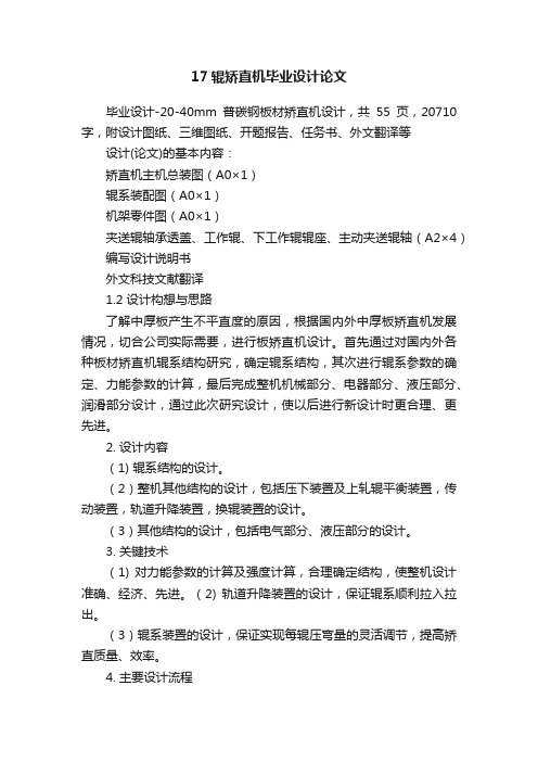
[_电机;2速机;3fm®;4—万向联轴器;mg漓压下装置; 6■^宜辐调角装置;7—上矫宜辐装配;8-下娇宜辐装配;宜中心线
图[斜辐轿直机结构
矫直辐辐形曲线的设计方法较多,下面介绍两 种常用的设计方法。 3.1圏解法
已知:被矫直管材的直径为必矫直辐与管材两 轴线间距离为两轴线之间的夹角为y,求矫直辗 的曲线。
随着矫直机智能化的发展,矫直辐压下装置5 和矫直辐调角装置6已可根据管材的不同规格实现 自动化调整。
3矫直辐的设计 斜辗矫直机辐形曲线是决定矫直效果的主要因
素。矫宜辐的最小宜径(即喉径)由被矫管材的最大
收稿日期:2020-11-02 作者简介:郭宝山(198—),男,山西文水人,毕业于山西省中北
大学,工^师,主要从事无缝钢管设备及棒线材设备的研发工作。
(上接第19页)
Exploration Scheme of Old Kilns for Flood Prevention and Irrigation in Special Thick Coal Seam Area Mining
Φ20~Φ90高精度棒材矫直机设计文献综述

重庆科技学院学生毕业设计(论文)文献综述题目Φ20 ~Φ90 高精度棒材矫直机学生姓名学号院(系)机械工程学院指导教师签字学生成绩(百分制)教务处制文献综述要求1.文献综述是要求学生对所进行的课题搜集大量情报资料后综合分析而写出的一种学术论文。
其特点“综”是要求对文献资料进行综合分析、归纳整理,使材料更加精练明确、更有逻辑层次;“述”就是要求对综合整理后的文献进行比较专门的、全面的、深入的、系统的描述和评价。
2.文献综述中引用的中外文资料,内容必须与课题或专业方向紧密相关,理工类不得少于10篇,其它不少于12篇。
3.文献综述不少于2000字,按规定格式用钢笔工整书写。
其所附注释、参考文献格式要求同正文。
文献综述的评阅评阅要求:应根据学校“文献综述要求”,对学生的文献综述内容的相关性、阅读数量以及综述的文字表述情况等作具体的评价。
指导教师的评语:指导教师签名年月日文献综述摘要:本文对钢材矫直工艺及工作原理,斜辊矫直机的工作原理、特点、结构等进行了介绍,同时对二辊棒材矫直机力能参数的计算进行了分析,提出了本次设计二辊棒材矫直机的基本思路。
关键词:棒材矫直工艺二辊棒材矫直机矫直力能参数前言金属棒材在轧制、加热、运输等各种加工过程中常常产生不同程度的弯曲、歪扭等塑性变形或内部残余应力;目前冶金市场上对金属棒材的成品精度要求也越来越高,因此轧制矫直设备在工厂中应用越来越普遍,对矫直设备的自动控制要求也越来越高。
在多辊棒材矫直机中,其矫直辊由多个辊子组成;设备在矫直过程中由于其棒材的弯曲程度不同;设备的矫直辊要频繁地进行压下及转角的调整(以下简称调整)。
在国内大多数同类设备中,其调整靠工人依据设备上的标尺,手动控制进行。
对于多辊设备调整起来就非常的麻烦,所需时间较长,为了提高生产率,必须提高设备的自动化程度,辊系的自动调整成为必然趋势。
随着液压控制技术的发展,运用三维扫描检测技术、跟随式检测机构、压力矫直专家系统等专有技术,实现了压力矫直的自动化、智能化,使压力矫直机得以融入连铸或锻造生产线,成为在线设备。
关于矫直机的设计与实现的毕业论文终稿(可编辑)

摘要矫直机是对金属棒材、管材、线材等进行矫直的设备。
轧制出的钢材常出现弧形弯曲、纵向和横向弯曲、瓢曲等缺陷,为此轧后钢材必须经过矫正。
本设计方案以太重集团生产的几种矫直机为参照,结合本案设计要求,设计了九辊矫直机。
本方案以弹塑性弯曲变形理论为设计依据。
主要包括以下内容:矫直机类型,矫直原理,矫直机结构的确定,矫直机基本力能参数计算、力能参数计算、电动机功率计算、工作辊和支撑辊的结构设计与校核、压下机构的设计计算及校核。
关键词:矫直机;工作辊;支承辊;压下机构AbstractStraightening machine is a equipment, which straighten metal bar, pipe workpiece, wire and so on. After rolling, there are arch bending, vertical and horizontal bending, protuberance in steel strip. So it must be straightened. I consulted straightening machine of Tai Zhong Group, combining with the design requirements of the program, then designed the nine roller straightening machine. The project is based on the theory of elasto-plastic bending. It includes the following: the type of straightening machine, the theory of straightening machine and the structure of straightening machine, the calculation of straightening machine’s basic parameters, the structural design and the checking of the work roll and backup roll, the structural design and checking ofscrewdownKey words: Straightening machine; work roll; backup roll; screwdown目录摘要IAbstract II目录III一、前言 11.1 课题研究的意义及现状 11.2 论文主要研究内容3二、方案确定 42.1 矫直机类型 42.2 矫直原理 62.3 矫直机结构8三、设计计算173.1 矫直机基本参数的确定173.2 辊式矫直机的力能参数确定19展望35参考文献36致谢37附件1 38附件2 46一、前言1.1 课题研究的意义及现状在板带材的轧制生产中,由于轧件温度不均,变形不均及轧后冷却不均、运输和其他因素的影响,致使轧制出来的产品常出现波浪弯和瓢曲等缺陷。
17辊矫直机毕业设计论文
17辊矫直机毕业设计论文毕业设计-20-40mm普碳钢板材矫直机设计,共55页,20710字,附设计图纸、三维图纸、开题报告、任务书、外文翻译等设计(论文)的基本内容:矫直机主机总装图(A0×1)辊系装配图(A0×1)机架零件图(A0×1)夹送辊轴承透盖、工作辊、下工作辊辊座、主动夹送辊轴(A2×4)编写设计说明书外文科技文献翻译1.2 设计构想与思路了解中厚板产生不平直度的原因,根据国内外中厚板矫直机发展情况,切合公司实际需要,进行板矫直机设计。
首先通过对国内外各种板材矫直机辊系结构研究,确定辊系结构,其次进行辊系参数的确定、力能参数的计算,最后完成整机机械部分、电器部分、液压部分、润滑部分设计,通过此次研究设计,使以后进行新设计时更合理、更先进。
2. 设计内容(1) 辊系结构的设计。
(2)整机其他结构的设计,包括压下装置及上轧辊平衡装置,传动装置,轨道升降装置,换辊装置的设计。
(3)其他结构的设计,包括电气部分、液压部分的设计。
3. 关键技术(1) 对力能参数的计算及强度计算,合理确定结构,使整机设计准确、经济、先进。
(2) 轨道升降装置的设计,保证辊系顺利拉入拉出。
(3)辊系装置的设计,保证实现每辊压弯量的灵活调节,提高矫直质量、效率。
4. 主要设计流程(1)一台完整的中厚板辊式矫直机应由机架、上下横梁、上下矫直辊装置、上下支承辊装置、引料辊装置、压下机构、弯辊装置、倾斜机构、换辊装置、检测系统、安全装置、除铁皮与冷却系统、传动装置、电动机及走台等所组成。
本次开发的中厚板材矫直机是强力重式矫直机,它功能多,矫直力强,结构独特,适合可逆矫直的要求。
(2)机架为铸焊结构,两片机架通过上下横粱联结。
机架加工精度高、刚性大、强度高、利于安装和运输,是矫直机各零部件承装的核心骨架。
(3)压下装置采用电动压下,可实现上辊系沿矫直方向整体少量倾斜运动及整体升降。
整个上辊系采用两台液压平衡缸平衡,消除活动横梁上面各受压件的间隙,压下行程需由位移传感器检测,以便操作。
矫直机毕业论文中英文资料外文翻译文献

矫直机论文中英文资料外文翻译文献外文翻译原文:AUTOMATING THE CONTROL OF MODERN EQUIPMENT FOR STRAIGHTENING FLAT-ROLLED PRODUCTS The company Severstal’ completed the successful introduction of new in-line plate-straightening machines (PSMs) on its 2800 and 5000 mills in August 2003 [1, 2, 3]. The main design features of the machines are as follows:●each machine is equipped with hydraulic hold-down mechanisms (toimprove the dynamics and accuracy of the machine adjustments and more reliably maintain a constant gap);●the machines have mechanisms to individually adjust each work roller with theaid of hydraulic cylinders (this broadens the range of straightening regimes that can be realized by providing a measure of control over the change in the curvature of the plate);●each work roller is provided with its own adjustable drive (to eliminate rigidkinematic constraints between the spindles);●the system of rollers of the PSM is enclosed in cassettes (to facilitate repairs andreduce roller replacement costs);●the PSM has a system that can be used to adjust the machine from a nine-rollerstraightening scheme to a five-●roller scheme in which the distance between the rollers is doubled (this is doneto widen the range of plate thick-nesses that the machine can accomodate).Thus, the new straightening machine is a sophisticated multi-function system of mechanisms that includes a wide range of hydraulically and electrically driven components controlled by digital and analog signals. The entire complex of PSM mechanisms can be divided into two functional groups: the main group, which includes the mechanisms that partici-pate directly in the straightening operation (the hold-down mechanisms, the mechanisms that individually adjust the rollers,the mechanisms that adjust the components fordifferent straightening regimes, the mechanism that moves the top roller of the feeder, and the main drive); the auxiliary group (which includes the cassette replacement mechanism, the spindle-lock-ing mechanism, and the equipment that cools the system of rollers). Although the PSM has a large number of mechanisms,the use of modern hydraulic and electric drives has made it possible to almost completely automate the main and auxiliary operations performed on the PSM and the units that operate with it.Described below are the features and the automatic control systems for the most important mechanisms of the plate-straightening machine.The operating regimes of those mechanisms are also discussed.The hydraulic hold-down mechanisms (HHMs) of the sheet-straightening machine function in two main regimes:the adjustment regime;the regime in which the specified positions are maintained.There are certain requirements for the control system and certain efficiency criteria for each regime.In the adjustment regime, the control system for the hydraulic hold-down mechanisms must do the following:●synchronize the movements of the hydraulic cylinders and keep the angulardeeflection within prescribed limits;●maximize speed in adjusting the machine for a new plate size;●maintain a high degree of accuracy in positioning the mechanisms;Fig. 1. Block diagram of the control system of the hydraulic cylinder.The control system has the following requirements when operating in the maintenance regime:●stabilize the coordinates of the top cassette and the top roller of the feeder with ahigh degree of accuracy;●minimize the time needed to return the equipment to the prescribed coordinateswhen deviations occur (such as due to the force exerted by a plate being straightened).Need for synchronization. Experience in operating the plate-straightening machine in plate shop No. 3 at Severstal’ has shown that the most problematic factor in adjusting the machineis the nonuniformity of the forces applied to the hydraulic cylinders. This nonuniformity is due to the asymmetric distribution of the masses of the moving parts of the PSM (in particular, the effect of the weight of the spindle assembly). Displacement of the “hydraulic zero point” relative to the “electrical zero point” in the servo valves is also a contributing factor.The latter reason is more significant, the smaller the volume of the hydraulic cylinder.Thus, the HHM of the top roller of the feeder is the most sensitive to drift of the zero point.There are also other factors that affect the dynamism,simultaneousness,and synchronism of the operation of the hold-down mechanisms:●differentiation of the frictional forces on parts of the hydraulic cylinders due todifferent combinations of deviations in the dimensions of the mated parts, despitethe narrow tolerances;●differences in the “springing” characteristics and the indices characterizing theinertia of the hydraulic supply channels (due to differences in the lengths of thepipes leading from the servo valves to the hydraulic cylinders).Thus, since the PSM is not equipped with devices to mechanically synchronize the operation of the cylinders, the ransmission of signals of the same amplitude to the inputs of the servo valves inevitably results in a speed difference that can seriously damage the mechanisms.To minimize and eliminate the effects of the above-mentioned factors, we developed an algorithm for electrical synchronization of the hold-down mechanisms.The HHM of the top cassette, composed of four hold-down cylinders and four balancing cylinders, is designed to ensuremobile adjustment of the machine to set the required size of straightening gap (in accordance with the thickness of the plate) andmaintain that gap with a specified accuracy in the presence .and absence of a load on the housings from the straightening force.The hydraulic system of the hold-down mechanism is designed in such a way that only one chamber of the hydraulic cylinders is used as the working chamber.The second chamber is always connected to the discharge channel.The top cassette is lowered when the balancing forces are overcome by the hold-down cylinders.The cassette is raised only by the action of the balancing cylinders.This arrangement has made it possible to eliminate gaps in the positioning of the equipment.The HHM of the top roller of the feeder consists of two hydraulic cylinders. Hydraulic fluid is fed into the plunger chamber when the roller is to be lowered and is fed into the rodchamber when it is to be raised.Control Principles. Individual circuits have been provided (Fig.1) to control the hydraulic cylinders of the hold-down mechanisms.The control signal (Xctl) sent to the input of the servo valve is formed by a proportional-integral (PI) controller (to improve the sensitivity of the system, we chose to use valves with “zero” overlap).The signal sent to the input of the controller (the error signal Xerr) is formed as the difference between the control-point signal for position (Xcpt) and the feedback signal (Xf.b).The latter signal is received from the linear displacement gage (G) of the given hydraulic cylinder.The gages of the HHM for the top cassette are built into the balancing hydraulic cylinders (HCs).The cylinders are installed in such a way that their movements can be considered to be equal to the displacements of the corresponding cylinder rods, with allowance for certain coefficients.The gages in the HHM for the top roller of the feeder are incorporated directly into the hold-down cylinders.The integral part of the controller is activated only during the final adjustment stage and during stabilization of the prescribed coordinate.When the displacements exceed a certain threshold value, the functions of the PI controller are taken over by a proportional (P) controller with the transfer function W(s) = k.Thus, Xctl(t) = kXerr(t).When there are significant differences between the displacements of the working rollers,the difference (error)between the control point and the feedback signal from the linear displacement gage reaches values great enough so that the output signal which controls the operation of the servo valve reaches the saturation zone.In this case, further regulation of the displacement rate and,thus synchronization of the movements of the cylinders becomes impossible as long as the error exceeds the value at which Xctl is greater than the boundary value for the saturation zone (Xsat).The limiting error–the largest error for which Xctldoes not reach saturation–is inversely proportional to the gain of the controller k: Xerr< Xsat/ k. Solving the given problem by decreasing k leads to a loss of speed in the adjustment of the PSM and a decrease in control accuracy during the straightening operation.Thus, to keep the control signal from reaching the saturation zone when there are substantial displacements, the system was designed so that the input of the controller is fed not the actual required value (Xrq) but an increment (∆X) of a magnitude such that the condition k∆X < Xsat is satisfied.The control point is increased by the amount ∆X after the position of the cylinder has been changed by the amount corresponding to the increment having the largest lag relative to the cylinder’s direction of motion. The adjustment of the control point is continued until the difference between the required value and the actual position of the mechanism becomes lessthan the increment:Xrq –Xf.b < ∆X.Then the input of the controller is fed the value Xcpt, which is equal to the required adjustment: Xcpt= Xrq.The adjustment is thus completed.Use of the principle of a stepped increase in the control point makes it possible synchronize the movements of the cylinders and set the control point with a high degree of accuracy for almost any ideal repetition factor.Mechanisms for Individual Adjustment of the Working Rollers.The plate-straightening machine is designed so that each working roller can be moved vertically, which is done by means of a hydraulic cylinder acting in concert with a V-belt drive.The cylinders are supplied with power from servo valves operated with proportional control.A linear displacement gage is built into each cylinder to obtain a feedback signal on the position of the roller.Since these gages are actually transmitinginformation on the position of the cylinder rods rather than the working rollers themselves, the following conversion is performed to obtain the rollers’ coordinates:Xrol= kredXf.b,where kred is the gear ratio of the drive;Xf.b is the position of the cylinder rod measured by the linear displacement transducers.Thus, a position feedback circuit is provided to control the position of each working roller. Figure 1 presents a diagram of one of the circuits.The control signals are generated by means of the PI controllere, which has made it possible to achieve a high degree of accuracy in adjusting the system without sacrificing speed.The individual drive of the rollers. The above-described design is based on the use of individual ac drives with motors of different powers fed from frequency converters. Each individual drive offers the following advantages over a group drive:●greater reliability thanks to the absence of additional loads on the components ofthe mechanisms due to differences between the linear velocities of the working rollers and the speed of the plate;●the possibility that the machine could continue to operate if one or even severaldrives malfunction;in this case,the corresponding rollers would be removed from the straightening zone;●the possibility that the linear velocities of the rollers could be individuallycorrected in accordance with the actual speed of the plate;such a correction could be made either as a preliminary measure (on the basis of measured and calculatedvalues) or during the straightening operation (on the basis of the data obtained from the frequency converters, which employ artificial intelligence).The main drive of the straightening machine rotates nine straightening rollers and two housing rollers.This drive must be highly reliable in operation, since the fact that the PSM is installed in the mill line means that sizable production losses can be incurred if the drive fails to work properly even for a short period of time.The requirements that must be satisfied by the drive are determined by the operational and design features of the machine as a whole:●the plate being straightened must create a rigid kinematic coupling between thestraightening rollers, the rollers of the housing, and the adjacent sections of the roller conveyors;●the plate should undergo elongation during the straightening operation as a resultof plastic deformation, with the increments in length being different on each working roller due to the differentiation of the bending radii;this situation leads to a nonuniform increase in the speed of the plate as it moves toward the end of the PSM;●it must be possible to use working rollers of different diameters (this being done,for example, due to nonuniform wear or regrinding);●the loads on the rollers should be differentiated in accordance with the chosenstraightening regime;●reverse straightening should be possible.In light of the above factors and the actual operating regimes of the plate-straightening machine being discussed here, the following requirements can be established for the electric drive:●regulation of speed within broad limits, including startup of the motors underload;●operation in the reverse regime;● a rigid characteristic ω = ƒ(M);●high degree of accuracy in maintaining the prescribed speed;●fully synchronous operation.The element base. The drive of the rollers was built with the use of asynchronous three-phase motors having a short-circuit rotor.The motors were designed by the German company VEM.They can continue to function under severe overloads and are reliable in operation.The motors are controlled by SIMOVERT frequency converters made by the German firm Siemens.Their modular design facilitates maintenance and repair, and the presence of a built-in microprocessor block makes it possible to execute most of the functions involved in controlling the operation of the drive (maintain the prescribed speed with a high degree of stability, recalculate the frequency of rotation in accordance with the actual diameters of the rollers, diagnose the condition o f the drive, control the drive’s operation, and exchange information on the PROFIBUS network).Motors of different powers are used in the system because of the differentiated distribution of the moments between the working ing different motors has made it possible to significantly reduce the cost of the electrical equipment and improve the performance characteristics of the machine as a whole.The machine has three main operating regimes: the working regime (semi-automatic and automatic), the transport regime, and the cassette replacement regime.Figure 2 shows a block diagram of the operations connected with realization of the working regime.In the semi-automatic variant of this regime, the operator controls the PSM from a control panel.In this case, the operator can do the following: choose the straightening regime from a database;correct the chosen regime;adjust the regime manually, which requires that the operator indicate the desired position of the bottom cassette (for five- or nine-roll straightening);adjust the gap between the top and bottom cassettes; set the coordinates for individual adjustment of the working rollers; choose the straightening speed and direction;generate a command to begin adjusting the machine to the specified regime.Fig. 2. Block diagram of the working regime of the PSM.The machine is adjusted to the chosen regime automatically.After the adjustment is completed, a signal is sent to the control panel indicating that the coordinates of the mechanisms have been changed and that the rollers have reached their prescribed working speeds.In the automatic variant of the working regime, the plate-straigthening machine isadjusted on the basis of data sent through a data network from a higher-level system. These data include the following information:●the thickness of the plate being straightened;●the group of steels (information on the properties of the material);●the temperature of the plate at the inlet to the PSM.The PSM is adjusted in several stages:●preliminary adjustment based on the plate thickness and steel group, for cold-rolledplates (t = 20°C);●further adjustment on the basis of data obtained from a pyrometer installed roughly50 m from the PSM;●final adjustment on the basis of data obtained from a pyrometer installed at theentrance to the machine.In the automatic variant, control over the roller conveyors adjacent to the machine is switched over to the control system of the PSM as the next plate approaches the machine.In this case, the plate cannot enter the working zone of the machine until the adjustment is completed.If it is necessary to pass a plate through the machine without straightening it, the machine is changed over to the transport regime.In this case, the top crossarm and the cassette are elevated a prescribed amount and the speed of the rollers is changed so that it is equal to the speed of the adjacent roller conveyors.The cassette replacement regime is used in the event of breakage of a roller or when it is necessary to regrind the working and backup rollers.In this case, the operator can control the operation of the auxiliary mechanisms:the spindle-locking mechanism, the roll-out cart, the mechanism that locks the bottom cassette and the cart in position, and the hydraulic cylinder that moves the cart.The mechanisms are fixed in position by means of noncontact transducers.PSM Control System. Control of the plate-straightening machine required the development of a powerful, high-capacity system that could provide the desired control accuracy in combination with rapid operation.The control system that was created is divided into two levels: the base level, and an upper level.The diagnostic system was created as a separate system.A second controller was also provided, to control the pump station of the PSM.The base level of the control system employs a SIMATIC S7 industrial programmable controller, while the upper level and the diagnostic system were built on the basis of standardcomputers.The computer used for the upper-level system also serves as the control panel for the PSM.Fig. 3. Network structure of the PSM control system.The different elements of the control system are linked by two loops of a PROFIBUS network (Fig.3).The first loop functions as the communications link between the controller, the upper-level computer, the diagnostics station, and the pump-station controller.The second loop links the PSM controller with the functional elements of the system (the frequency converters, linear displacement gages, and remote input/output module).The functions of the control system were divided between the base level and the upper level on the basis of the following principle: the base level was assigned all of the operations that involve receiving data from the sensors installed on the mechanisms, obtaining information from the automated process control system on the plate being straightened, and generating and transmitting control signals for the executive mechanisms (actuators); the upper level was assigned the functions of archiving the control points and monitoring the operation of the control panel.The following specific functions are performed by the base level of the automation system:obtaining the assigned straightening parameters (roller speeds, the coordinates of the top crossarm, and the coordinates of the rollers relative to the crossarm) from the upper-level system;●processing the parameters and sending corresponding control signals to the actuators;●obtaining information from the sensors installed on the mechanisms to determinewhether or not the PSM is properly set and ready for the straightening operation;●obtaining information from the feedback transducers installed on the mechanisms tocalculate the control actions;●analyzing the readings of the sensors to determine the accuracy of the data;TABLE 1. Specifications of the Plate-Straightening Machines●exchanging data with the pump-battery station (PBS) of the PSM and transmittingthe station’s operating parameters to the upper-level system for display;●receiving signals from the upper-level system for manual control of the machine andthe PBS;●obtaining initial data from the upper-level system for automatic correction andtransmission of the data in order to make the appropriate adjustments.The functions of the upper-level automation system are as follows:●entering data on the straightening regimes for subsequent selection of the regime andrecording that information in a database;●manually choosing the straightening regime from the database for the correspondingplate (this is done by the operator);●automatically choosing the straightening regime from the database on the basis ofinformation obtained from the upper-level system;●manually controlling the machine in the straightening and cassette-replacementregimes;●indicating the positions of the mechanisms based on readings from the sensors andthe positions of the limit switches;●indicating the presence of a plate in the working zone of the PSM;●indicating the temperature of the plate measured by the pyrometer;●visually representing the straightening regimes and machine adjustments;visually representing the state of the machine’s mechanisms and the PBS for diagnostic purposes.Remote input-output module ET200 is used to supply power to the unregulated drives.The cabinet containing the relays and contacts for these drives is located a considerable distance from the e of the module has made it possible to significantly shorten the connecting cables.Diagnostic System. The heavy concentration of electrical and hydraulic equipment included as part of the PSM–equipment which is located an appreciable distance from the machine itself and is often in hard-to-reach places–makes it more difficult to service the machine and locate the source of problems.To facilitate maintenance of the PSM and shorten repair time, it was necessary to build an advanced diagnostic system.The system is based on an industrial computer installed at the control post.It diagnoses the state of various mechanisms of the PSM, as well as its hydraulic and electrical equipment.The system can be used to evaluate the condition of the automatic switches, the temperature sensors of the motors, the linear displacement gages, terminals of the local PROFIBUS network, the currents, speeds, and direction of rotation of the motors, and other equipment and parameters.The diagnostic system can also be used to establish the operating protocol of the PSM.Its archives contains data on the time and types of errors and equipment failures that occur, the coordinates of the mechanisms, motor currents and speeds, and other information.To make the control system more reliable, the software and hardware of the diagnostics station are identical to the corresponding components of the control system’s upper level.When problems occur with the operation of the control computer, the PSM control functions can be transferred to the computer of the diagnostic system.Conclusions.The NKMZ has worked with its original partners in the Commonwealth of Independent States (CIS) to successfully introduce plate-straightening machines equipped with a modern automated control system. Use of the machines makes it possible to minimize and almost completely eliminate the dependence of the quality of the finished plates on the skill of the machine operator.The control system, together with its convenient user interface,allows even personnel with no special training to quickly master the operation of the machine.The production of high-quality products is assured as a result of the exact movements of the machine’s mechanisms and the accuracy with which their positions are maintained, which owes to the use of precision equipment with proportional control and special controlalgorithms.In addition, the machine is equipped with a sophisticated diagnostic system which also records its key operating parameters.The availability of the system facilitates maintenance and repair of the machine’s many complex components.译文:现代化矫直轧制薄品设备的自动化控制谢韦尔钢铁公司在2003年8月成功完成了新引进的规格为2800—5000米尔的直线式钢板矫直机(平台相关模型)。
矫直机毕业设计
矫直机毕业设计矫直机毕业设计随着现代工业的发展,机械设备在生产过程中起到了至关重要的作用。
其中,矫直机作为一种常见的机械设备,被广泛应用于金属加工、汽车制造等领域。
本文将围绕矫直机的毕业设计展开讨论,探究其设计原理、技术要点以及未来发展趋势。
一、设计原理矫直机的设计原理主要基于材料力学和机械原理。
其基本原理是通过对金属材料的弯曲变形进行逆向力学分析,从而实现材料的矫正。
矫直机通常由上、下两个辊轮组成,通过辊轮的旋转和压力调节,对金属材料进行弯曲矫正。
在设计中,需要考虑材料的性质、工件的尺寸和形状等因素。
通过对这些因素的分析和计算,可以确定矫直机的结构参数、工作方式以及控制系统等设计要点。
二、技术要点1. 结构设计:矫直机的结构设计是整个毕业设计的核心。
需要考虑矫直机的稳定性、刚度和精度等因素。
合理的结构设计可以提高矫直机的工作效率和矫直质量。
2. 辊轮设计:辊轮是矫直机的核心部件,直接影响到矫直效果。
辊轮的材料选择、表面处理以及尺寸设计都需要进行详细的分析和计算。
3. 控制系统设计:矫直机的控制系统需要实现对辊轮的旋转速度、压力和位置等参数的精确控制。
控制系统的设计涉及到传感器的选择、电气元件的布置以及控制算法的优化等方面。
4. 安全设计:矫直机在工作过程中存在一定的危险性,因此安全设计至关重要。
需要考虑到紧急停机、过载保护以及防护装置等方面,确保操作人员的安全。
三、未来发展趋势随着科技的不断进步,矫直机也在不断发展和改进。
未来,矫直机的发展趋势主要体现在以下几个方面:1. 自动化:随着工业自动化水平的提高,矫直机将更加智能化和自动化。
通过引入机器学习和人工智能等技术,可以实现矫直过程的自动控制和优化,提高生产效率和产品质量。
2. 精确度和稳定性:随着对产品质量要求的不断提高,矫直机的精确度和稳定性也将成为关注的焦点。
未来的矫直机将更加注重精确度的控制和稳定性的提升,以满足高精度加工的需求。
3. 多功能性:矫直机在不同行业中的应用需求也在不断增加,因此未来的矫直机可能会具备更多的功能和适应性。
钢管矫直机毕业论文
钢管矫直机毕业论文钢管矫直机毕业论文1.绪论1.1 矫直设备的发展1.1.1 矫直设备的发展概况矫直技术在金属条材加工的后部工序中得到广泛应用,对产、成品的质量水平有着很大的影响。
早在20世纪初,就已经出现了二辊式矫直机用于矫直圆材。
20世纪30年代中期,222型六辊式矫直机的发明显著提高了管材矫直质量。
20世纪60年代中期,为了解决大直径管材的矫直问题,XXX研制成功313型七辊式矫直机。
自70年代我国改革开放以来,我们接触到了许多国外设计研制成果,从小到φ1.6mm金属丝矫直机到大到φ600mm管材矫直机,从速度达到300m/min的高速矫直机到精度达到0.038mm/m的高精度矫直机,我们都进行了引进。
同时,我国也研制出了许多先进的矫直设备。
进入90年代,我国在赶超世界先进水平方面又迈出了一大步,一些新研制的矫直机获得了国家的发明专利,一些新成果获得了市、省及部级科技成果进步奖,有的获得了国家发明奖。
近年来,我国在反弯辊形七斜辊矫直机、多斜辊薄壁转毂式矫直机、平行辊异辊距矫直机及矫直液压自动切料机等研制方面相继取得了成功。
1.1.2 矫直作用经过轧制和热处理的管材存在一系列缺陷,其中主要的是纵向弯曲和横断面的椭圆度。
为了消除这些缺陷,需要设置斜辊式钢管矫直机。
在矫直过程中,钢管在矫直辊间作直线前进的同时还进行旋转运动,通过钢管在矫直辊中反复多次弹性弯曲使钢管达到矫直的目的。
1.2 矫直设备分类1.2.1 矫直机的分类按照工作原理不同,矫直机可以分为五大类。
第一类称为反复弯曲矫直机,它们是靠压头或辊子在同一平面内对工件进行反复压弯并逐渐减小压弯量,直到压弯量与弹复量相等而变直。
第二类称为旋转弯曲式矫直机,是工件在塑性弯曲状态下以旋转变形方式从大的等弯矩区向小的等弯矩区过渡,在走出塑性区时弹复变直。
第三类称为拉伸矫直机,它依靠拉伸变形把原来长短不一的纵向纤维拉成等长度并进入塑性变形后经卸载及弹复而变直。
168钢管矫直机毕业设计说明书

目
录
摘 要 ................................................................................................................ I Abstract ..........................................................................................................II 第 1 章 绪论 ....................................................................................................1 1.1 课题背景 .............................................................................................1 1.2 课题背景 .............................................................................................2 1.3 课题背景 .............................................................................................3 第 2 章 斜辊矫直机的原理 .............................................................................4 2.1 矫直原理 .............................................................................................4 2.2 矫直机的分类 ....................................................................................7 2.3 矫直机辊系配置的四种基本形式 .....................................................9 2.4 斜辊矫直机的类型及选择........................9 2.5 斜辊矫直机的特点 .......................................................................... 15 2.6 矫直机的机架和传动设计............................................................... 15 2.6.1 机架设计..................................................................................... 15 2.6.2 传动设计..................................................................................... 16 2.7 新旧矫直机的比较 ............................................................................ 16 2.7.1 常规斜辊矫直机的特点 ............................................................. 16 2.7.2 常规斜辊矫直机存在的主要缺点 .............................................. 16 2.7.3 本矫直机的工作原理和工作过程 .............................................. 17 2.7.4 本机组的主要特点和先进性 ...................................................... 20 2.7.5 设备组成及结构特点 ................................................................. 20 2.7.5.1 矫直机的传动装置 .................................................................. 20 2.7.5.2 矫直机本体 .............................................................................. 20 第 3 章 矫直机基本参数的设计与计算 ........................................................ 22 3.1 基本参数的选择原则 ........................................................................ 22 3.1.1 矫直辊辊颈 D 的确定 ................................................................ 22
- 1、下载文档前请自行甄别文档内容的完整性,平台不提供额外的编辑、内容补充、找答案等附加服务。
- 2、"仅部分预览"的文档,不可在线预览部分如存在完整性等问题,可反馈申请退款(可完整预览的文档不适用该条件!)。
- 3、如文档侵犯您的权益,请联系客服反馈,我们会尽快为您处理(人工客服工作时间:9:00-18:30)。
钢管矫直机毕业论文1绪论1.1矫直设备的发展1.1.1矫直设备的发展概况矫直技术多用于金属条材加工的后部工序,在很大程度上决定着产、成品的质量水平。
20世纪初已经有矫直圆材的二辊式矫直机。
20世纪30年代中期发明222型六辊式矫直机,显著提高了管材矫直质量。
20世纪60年代中期,为了解决大直径管材的矫直问题,美国萨顿公司研制成功313型七辊式矫直机。
20世纪70年代我国改革开放以后接触到大量的国外设计研制成果,有小到φ1.6mm金属丝矫直机和大到φ600mm管材矫直机。
有速度达到300m/min的高速矫直机和精度达到0.038mm/m的高精度矫直机。
同时也引进许多先进的矫直设备。
进入90年代我国在赶超世界先进水平方面又迈出了一大步,一些新研制的矫直机获得了国家的发明专利;一些新成果获得了市、省及部级科技成果进步奖;有的获得了国家发明奖。
近年来我国在反弯辊形七斜辊矫直机,多斜辊薄壁转毂式矫直机,平行辊异辊距矫直机及矫直液压自动切料机等研制方面相继取得成功,1.1.2矫直作用轧制和热处理后的管材有一系列的缺陷,其中主要的是纵向弯曲和横断面的椭圆度。
为了消除这些缺陷,需设置斜辊式钢管矫直机,在矫直过程中,钢管在矫直辊间作直线前进的同时还进行旋转运动,通过钢管在矫直辊中反复多次弹性弯曲使钢管达到矫直的目的。
1.2矫直设备分类1.2.1矫直机的分类按工作原理不同划分为五大类。
第一类称为反复弯曲矫直机,它们是靠压头或辊子在同一平面内对工件进行反复压弯并逐渐减小压弯量,直到压弯量与弹复量相等而变直。
第二类称为旋转弯曲式矫直机,是工件在塑性弯曲状态下以旋转变形方式从大的等弯矩区向小的等弯矩区过渡,在走出塑性区时弹复变直。
第三类称为拉伸矫直机,它依靠拉伸变形把原来长短不一的纵向纤维拉成等长度并进入塑性变形后经卸载及弹复而变直。
第四类称为拉弯矫直机。
它是把拉伸与弯曲变形合成起来使工件两个表层的较大拉伸及全截面的拉伸变形三者不在同一时间发生,全断面各层纤维的弹复变形也不是同时发生的,既防止了板带的断裂,又提高了矫直质量。
第五类称为拉坯矫直设备,它是在拉动连铸坯下行的同时使铸坯的弧形弯曲渐伸变直,其拉力主要用于克服外部阻力,而铸坯本身在高温状态下所需的矫直力是较小的。
具体进一步分类如图1.1所示:,图1.1(5)拉坯矫直机拉坯矫直机在连铸系统中占有重要位置,取得了很大发展,已经自成体系。
1.2.2钢管矫直机分类及适用范围在矫直管、棒等圆形断面条材时若采用平行辊矫直机则存在两个致命的缺点:第一,只能矫直圆材垂直于辊轴的纵向剖面上的弯曲。
若矫直其它各方面的纵向剖面的弯曲常需要进行多次的变方位的矫直过程;第二,圆材在矫直过程中容易产生自转现象,不仅达不到矫直目的,反而要产生严重的螺旋形弯曲(俗称麻花弯),使产品报废。
为了消除上述的缺点,在生产中常采用斜辊矫直机。
常见的斜辊矫直机的类型及用途:1、2斜辊矫直机:这种矫直机用于矫直棒材,也可用于矫直厚壁管材。
2、3斜辊矫直机:只适用于矫直长度较小,直径较大,壁厚很薄的小量管材,故至今没有发展起来。
3、多斜辊矫直机(1)、212型5辊式矫直机:适用范围宽,表面质量好,可以一机多用。
但上辊稳定性低,传动系统复杂,制造成本高。
(2)、222型6辊式矫直机:这种矫直机既可以矫直管材又可以矫直棒材。
4、6辊以上的斜辊矫直机(1)、12121型7辊式矫直机:这种矫直机主要用于矫直高强度管材及厚壁管材,不仅可以矫直管材的弯曲度也可以消除管材的随圆度。
(2)、1-12(8)型8辊式矫直机:它有较广的适用范围,可以用于管材张力减径生产线、焊管生产线、挤压生产线、电镀生产线及有色金属管的轧制生产线。
5、313型斜辊矫直机:这种矫直机只能用于大直径圆材的矫直。
1.2.3斜辊矫直机的典型辊系1、1-1(5)辊系如图1.2(a)所示,上下辊一一交错,此辊系常驻由5个辊子组成,上三下二,上辊短,下辊长。
入口侧长辊处可使圆材得到较大的均匀的塑性弯曲,到出口侧长辊处则按较小的塑性弯曲进行压弯在反复后达到矫直的目的。
2、212辊系如图1.2(b)所示,5辊式管材矫直机的专用辊系,它把原来辊系中两端短辊移到长辊上方,形成两对压紧辊。
3、2辊系如图1.2(c)所示,它的矫直功能来自辊形的凸凹变化,它是以矫直短圆材的独特性而受到重视,又以能矫直圆材两端和能压光圆材表面而得到不断发展。
4、12121辊系如图1.2(d)所示,可以把它看成是图1.2(a)和图1.2(b)两种辊系的综合。
圆材在压紧辊间的塑性变形区得到延长,压扁矫直和圆整能力得到增强,矫直速度有所提高,对管棒材矫直都可适用。
5、222或2-2(6)辊系如图1.2(e)所示,6个辊子全部为驱动辊,这种辊系的两端辊主要起压扁矫直和圆整作用,并有利于工件的咬入,中间辊可以保证较长的塑性弯曲区,使已经压扁矫直部分尚存的弯曲得到矫直。
6、2221或2-21(7)辊系如图1.2(f)所示,此辊系是在222辊系后面增加一辊,新增加一个辊子起的作用很大,它可以增大第3对辊处塑性弯曲区的长度,并在压下量合适的条件下易于达到工作弹复变直的要求。
而且这种改进的辊系对于矫直管材也有提高质量的作用。
7、21-1(9)辊系如图1.2(g)所示,这种矫直辊系入口端的一对压紧辊可以保证工件快速咬入和对管材的压扁矫直作用,3个长辊处可以实现3段递减的等曲率性变性区,有助于提高矫直速度。
8、313辊系如图1.2(h)所示,此辊系比较特殊,前后各用3个斜辊按相隔120°环抱管材,既可以按三角压扁方式起到矫直和圆整作用,又可以利用中间辊进行三段的连续压弯,可用较小的压弯改善压扁矫直效果,使大直径薄壁管找到了较好的矫直途径。
图1.2 斜辊矫直机的典型辊系1.3斜辊矫直的工作原理斜辊矫直机一般采用旋转反弯矫直原理,旋转反弯矫直主要用于圆材矫直,旋转矫直中最常见的方法是多斜辊矫直法,是在斜辊矫直机上进行的。
由于圆材的原始弯曲是多方位的。
因此,在矫直时要使圆材绕轴线旋转,并在旋转的同时能使其反弯程度由小到大,再由大到小连续变化,才能使任何方位的原始弯曲都能得到可靠的反弯矫直。
斜辊矫直机的作用是强迫圆材在反弯状态下旋转前进,达到矫直的目的。
如图1.4所示:1——K-x曲线2——M-x曲线图1.4 旋转反弯矫直过程中弯矩与塑性区分布圆材在斜辊间反弯前进,走过每一个螺旋导程时反弯量的减少梯度和圆材塑性变形层的深度及均匀度是矫直质量的决定因素。
因此,圆材在塑性区内旋转次数或称高频弯曲次数越多,各处纵向纤维的变形量差别越小,结果各处的残余曲率差也越小,从而使圆材变直。
相对而言,如果使弯曲延长,在旋转导程不变的条件下,也等于增加高频弯曲次数,同样可提高矫直质量。
1.4φ219矫正机简介本次毕业设计的φ219矫正机采用八柱预紧式封闭机架和2-2-2-1复合辊系统。
下面简述工作过程和结构特点。
矫直机组具有手动控制和半自动控制两种工作方法。
手动控制用于安装调试,换辊,检修作业;半自动控制用于正常矫直生产作业。
其机组工作过程简述如下:上料台架上排布好待矫直的钢管后,拔料器动作将一支待矫直钢管送入输送辊道。
布轩在输送辊道的光电检测装置检测到钢管后,入口辊道升起,输送钢管前进;当布轩在入口辊道出口端的光电检测装置检测到钢管后,入口导板动作,使钢管对中顺利进入矫直机;当钢管头部被咬入第一对矫直辊后,入口导板打开,入口辊道下降,钢管在桥直机城经反复旋转弯曲变形后被矫直。
当钢管尾部离开第七号辊(导辊)后,出口辊道升起,将矫直后的钢管输送到下一工序,即完成一根钢管的矫直。
当钢管离开第三对辊子后,主传动系统发出信号指令输入辊道抬起迎接下一根待矫钢管。
2、结构特点:(1)、采用了八柱预紧式封闭机架和2-2-2-1复合辊系统,提高机架刚度和矫直度。
(2)、上辊座升降采用二柱导向,导向精度较高,安装调整方便。
(3)、上辊采用液压平衡和锁紧,消除了螺旋副的间隙和其他安装间隙,(4)、提高了机架的刚度,消除了咬入时的冲击。
(5)、下辊采用液压缸锁紧,工作可靠。
(6)、下辊升降电气传动安装在机座侧面,以便于检修和调整。
(7)、转角调整采用电机螺旋升降器机构(8)、矫直辊轴承座与转盘做成一体式(9)、换辊工具采用杠杆平衡砣结构形式。
(10)、润滑(稀油和干油)按钮安装在主操作台上,以方便操作。
2 矫直机总体方案的确定2.1矫直方案及传动方案的确定2.1.1矫直方案方案一:采用2-2-2-1型7辊式矫直机,此矫直机是使用数量最多的矫直机之一。
这种矫直机既可矫直管材也可以矫直棒材,具有稳定性高,矫直表面质量好,操作方便等优点。
方案二:采用2-1-2型5辊式矫正机,这种矫直机的优点是适用范围宽,表面质量好,可以一机多用。
缺点为上辊稳定性低,传动系统复杂,制造成本高。
方案三:采用1-2-1-2-1型7辊式矫正机,这种矫直机主要用于矫直高强度管材及厚壁管材,可以保持工作的良好的表面质量,并且可以提高矫直速度。
所以它有较广的适用范围,可以用于管材张力减径生产线、焊管生产线等。
但制造成本高。
综上分析,采用方案一。
2.1.2传动方案斜辊矫直机的传动方式有齿轮和万向接轴传动两种。
方案一:齿轮传动如图2.1所示1-长辊2-拉杆3-右立板4-集油盘5-端板6-传动轮8-短辊9-左立板10-压下手轮图2.1 卧式矫直机齿轮传动此图为齿轮传动的卧式斜辊矫直机,它是由两个分配轴及圆锥齿轮直接传动矫直辊的。
这种传动比较紧凑,调节辊子斜角的范围可以很大,但辊子轴头齿轮受辊径限制不能太大,其强度也受限制。
此外,齿轮系统包含在辊座转盘之内,润滑及密封也不太方便。
方案二:万向接轴传动(如图2.2所示)图2.2 立式斜辊矫直机结构图万向接轴的一端与辊子轴头相联,电动机与减速分配齿轮箱的出轴相联,电动机与减速分配齿轮箱用联轴器联接。
这种传动方式使润滑、维修及换辊等工作得到改善。
此图为立式机架的斜辊矫直机。
这种矫直机采用万向接轴传动比较普遍,其优越性更大。
电动机及减速分配齿轮箱可单独装在地基上,与机器本体分离较远,使结构明显简化。
具有调节方便,工作线高度不变,机器本体与传动系统的震动互不干扰等优点。
由于其上下辊都可传动,因此,咬入条件及表面质量有改善。
这种矫直机传动方式的不足之处是占地面积和机架高度大。
2.2上横梁的压下装置2.2.1上横梁工作原理描述为适应不同规格钢管能在矫直机中顺利的实现矫直,上横梁装配必须实现以下功能:1、应不同规格的待矫直钢管,上、下工作辊系中的辊距要求可调,同时必须能够承受上工作辊系传递给上横梁的反力;2、矫直机要能稳定、精确矫直,必须在工作过程中上工作辊系不能上、下窜动;保证矫直辊辊面与钢管能够良好的接触,矫直辊必须圆周方向能够调整;3、矫直机要达到高精度,上、下工作辊必须锁紧,在工作过程中不能转动;2.2.2压下调整方案的确定为了满足上述工作原理要求,下面分别对上述四点要求分别阐述:1、矫直机要适应不同规格的待矫直钢管,上、下工作辊系中的辊距要求可调。