ARTIS刀具监控参数说明V3.8.8.6
ARTIS刀具及机床状况监控系统说明-V1.1
ARTIS 刀具及机床状况监控系统ARTIS 刀具及机床状况监控系统是实时可视在线监控,在加工过程中,可准确检测到断刀、缺刀状况,对钝刀状况也可做出及时判断。
一旦出现异常状况(断刀、缺刀),机床便可立刻停机,进行处理,避免了刀具、工件及机床的再次损伤,保证了产品质量,有效地降低了运行成本,为用户提高了经济效益。
ARTIS 刀具及机床状况监控系统是一个硬件加软件的系统。
PCI 或是ISA 插槽形式的CTM 卡是系统的核心部件,DTA 是数字式扭力适配单元,我们称之为软件(扭矩)传感器,CTM+DTA 就组成了运用最广泛的刀具监控系统。
采用ARTIS 不同的传感器(软件(扭矩)传感器、力、震动、声波、加速度、功率…),可对加工及机床状况(如主轴状况)进行监控。
根据不同应用(要求),还有相应的软件相支持。
对于大批量加工,ARTIS 系统采用“Standard ”监控方式;对于加工时间较长的小批量产品加工,ARTIS 系统采用“DX/DT”监控方法。
采用ARTIS 的自适应控制软件(AC :Adaptive control ),可以根据切削载荷的变化对进给速度进行调整,可有效保护刀具、提高效率。
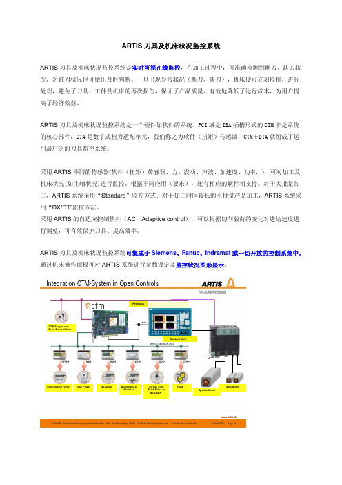
ARTIS 刀具及机床状况监控系统可集成于Siemens 、Fanuc 、Indramat 或一切开放的控制系统中,通过机床操作面板可对ARTIS 系统进行参数设定及监控状况图形显示。
www.artis.de©ARTIS Gesellschaft für angew andte Meßtechnik mbH Sellhorner Weg 28-30 D-29646 Bispingen-Behringen –Alle Rechte vorbehalten 12/2009/RS Page 10Integration CTM-System in Open ControlsSpindel-Motor Achs-MotorenSteuerungsbedienfeld NCDTA Torque andFeed Force ValuesTension and Force True Power Acoustic AccelerationVibration Torque and Feed Force inNm and N Fluid Spindle Motor Axis Motor Control UnitProfibus针对于非开放系统(如:Fanuc 18i, 31i),ARTIS 提供了独立的监控系统予以配合。
ARTIS刀具监控系统在数控机床上的开发应用
—
F u n c t i 0 n U s 功 能部 件
AR T I S刀 具 监 控 系 统 在 数 控机 床 上 的 开发 应 用
邓 凌① 许翠芳① 乔永 忠②
( ① 北 京航 空制造 工 程研 究所 , 北京 1 0 0 0 2 4 ; ② 成 都 飞机 工 业 ( 集 团) 有 限责任公 司 , 四川 成 都 6 1 0 0 9 2 )
工 成本 , 加工 周期 长 , 加工难度大 , 如 果 在 加 工 过 程
主轴 , 最 高转速 达 6 0 0 0 r / m i n , 具有 主轴 功 率 大 、 扭 矩 大、 变 速范 围大 、 转速 高 等 特 点 , 适 用 于 由难 加 工 材 料 制 成 的结构 复杂 、 精 度要 求 高 的大 型 整 体 结构 件 的加 工 。机 床配 置 西 门 子 S I N U M E R I K 8 4 0 D P o w e r l i n e数 控 系统 , S I MO D R I V E 6 1 1 D全数 字 交 流伺 服 驱 动 及 伺 服 电动 机 。为保 证加工 质 量 , 提 高加 工效率 , 有 必要 应 用A R T I S监控 系 统 对 机 床 刀具 工 作 状 态 、 碰撞 、 主 轴
随着 制 造业技 术 的不 断 进 步 和发 展 , 国 内航 空 制 造领 域对 提 高难加 工材 料工 件加 工效 率 和加工 质量 的 要求 也越 来越 高 。数 控 加 工 中 , 因各种 原 因发 生 的刀 具 磨损 、 刀具 断裂 、 主轴 碰撞 等故 障都 会对 正在 加工 的 工件甚 至 机床 本身 造成 损坏 。由于难 加工 材料 工件 加
t e r t ha n b e f o r e d u in r g mi l l i n g p r o c e s s . Ke ywo r d s:ARTI S;To o l s Re a l -t i me Mo n i t o r i ng;CNC Ma c hi n e To o l s
刀具软件使用说明书

软件使用说明书初始用户名为管理员,初始密码为aa.进入到系统后可以再添加一些用户,方便其它人操作。
打开刀具参数视觉检测用户程序,初始界面如图1所示。
图4。
1 登录界面选择相应的用户名及输入正确的密码,即可进入系统:如下如图所示图4。
2 系统界面本程序分为三大模块:刀具管理、系统管理、通信。
一,首先进入系统管理,点击菜单栏上的系统管理菜单;如下图所示有三个子菜单:添加管理员、修改密码、退出系统。
图片4。
3 系统管理(1)点击添加管理员可以添加管理员,方便其它人操作该系统。
输入用户名及密码就可以添加管理员了。
如下图所示图片4.4 新增用户(2)点击修改密码就可对当前用户的密码进行修改,可以修改为自己熟悉的密码或复杂的密码,以防被不法分子破解.如下图所示:图4。
5 修改密码(3)点击退出系统,系统将退出,所有窗口将被销毁。
二,进入刀具管理,刀具管理模块有二个子模块:刀具类别管理和刀具信息管理。
(1)刀具类别管理:刀具类别管理又有两个子项:刀具类别添加和刀具类别修改。
点击刀具类别添加,输入种类名称和类别的编号就可以添加刀具类别,如下图所示:图4。
6 刀具类别添加点击刀具类别修改会出现以下界面:图 4.7 刀具类别修改然后点击界面下方的修改按钮,就可以上面的列表中进行修改了,最后点击下方的保存。
若弹出以下对话框,说明修改成功了。
图4。
8 保存成功对话框(2)刀具信息管理刀具信息管理模块有三个子项,如下图所示:图4.9 刀具信息管理<1〉点击添加刀具信息,输入刀具编号、刀具长度、刀具名称、刀具材料、刀具名称、刀具转速、刀具直径、刀具前角、主偏角、刃倾角,选择相应的刀具类别,最后点击确定就可以添加一项刀具信息了。
如下图所示:图4。
10 添加刀具信息<2>点击修改刀具信息,进入以下界面:图4。
11 刀具信息修改首先点击下方的修改按钮,就可以在上面的列表中修改相应的参数了,最后点击保存,如果弹出保存成功的对话框,即说明修改刀具信息成功。
ARTIS CTM-V6刀具监控系统应用不同传感器的试验对比
扫码了解更多使用刀具监控系统可以有效地降低车间生产的运营成本,提高智能车间、柔性生产线的可靠性。
但是由于ARTIS刀具插槽的数控系统,可以尝试使用CFM4力矩传感器配工控机的方式来实现。
本文监控了刀具极限加工时的损耗和控制效果,对比不同数据采集方式的优缺点。
用以选择适合intelligent manufacture智能制造2018年 第10期冷加工71曲线:使用新刀试切样件,所得信号的峰值设置为100%,面积设置为100%。
即为学习曲线(图3~图5中淡绿色填充图)。
学习曲线是理想曲线,这时刀具完全没有磨损。
ARTIS 系统以此曲线作为标准曲线参照,进行加工的调整及报警参考。
(2)缺刀参数设置:缺刀曲线面积小于50%时系统提示缺刀报警。
(3)钝刀参数设置:更换到一把工艺认为已经磨损严重,不再使用的旧刀,试切。
记录面积数值130%,峰值数值130%,将钝刀面积数值设置为125%。
当实际加工时,实际切削面积大于设置的钝刀面积时,系统将提示钝刀报警。
钝刀设置值是根据实际情况而定的,出现实际钝刀报警而发现刀具磨损不严重,则证明钝刀设置偏低,调整钝刀报警上限到148%。
(4)断刀参数设置:断刀报警值暂时设置130%。
当实际加工出现断刀报警后,发现刀具并没有断,证明断刀报警值偏低,可以对断刀上限值进行相应的调整如150%。
(5)实际切削监测图形如图3~图5所示,上面窗口为DTA 窗口,即系统采集西门子电动机扭矩信图2 CFM4连线图图1 DTA 连线图 图3 学习曲线图4 加工试验曲线变化图5 大切深试验曲线变化号;下面窗口为CFM4窗口,即系统采集力矩传感器信号。
由图形可以分析出,绿色部分为学习曲线,可以看出DTA 曲线约30%,CFM4曲线约40%。
深蓝色部分为实际切削过程中与学习曲线重合的部分。
红色部分为实际切削过程中超出学习曲线的部分,可以看出DTA 曲线约40%,CFM4曲线约60%。
黄色横线为断刀上限,DTA 曲线设置为77%,CFM4曲线设置为100%。
加工中心刀柄参数-概述说明以及解释

加工中心刀柄参数-概述说明以及解释1.引言1.1 概述概述部分的内容:刀柄作为加工中心的重要组成部分,其参数的选择和优化对于整个加工过程的效率和质量具有关键性的影响。
本文旨在深入探讨刀柄参数的意义和重要性,以及这些参数的分类和影响因素。
通过对现有研究的综合分析和总结,我们希望能够对刀柄参数的优化提出有价值的建议,并对未来刀柄参数的发展趋势进行展望。
在加工中心中,刀柄是刀具安装在主轴上的关键部件,其主要作用是提供稳定的支撑和合理的刀具位置。
刀柄的合理选择不仅可以提高加工精度和效率,还能延长刀具的使用寿命。
因此,对刀柄参数的研究和优化显得尤为重要。
刀柄参数的重要性主要表现在以下几个方面:首先,刀柄的形状和尺寸会直接影响刀具的刚度和振动特性,从而影响加工中心的切削性能;其次,刀柄的连接方式和刀柄-刀具界面的匹配性能会影响刀具的安全性和稳定性;此外,刀柄的材料选择和表面处理也与刀具寿命直接相关。
针对刀柄参数的研究,主要可以从以下几个方面进行分类:刀柄的形状和尺寸参数、刀柄的连接方式参数、刀柄的材料参数以及刀柄的表面处理参数。
这些参数在加工中心的切削过程中都会产生不同程度的影响,并且受到多种因素的共同作用。
在本文的后续章节中,我们将对刀柄参数的分类和影响因素进行详细的阐述和分析,并在结论部分总结刀柄参数的重要性,并针对优化刀柄参数提出建议。
最后,我们还将展望刀柄参数在未来的发展趋势,为进一步的研究提供一定的参考。
1.2 文章结构文章结构部分的内容应该包括对整篇文章的章节划分和每个章节的内容简介。
在本篇文章中,共分为三个章节:引言、正文和结论。
引言部分主要介绍文章的背景和目的。
其中1.1概述简要说明了本文要讨论的内容是加工中心刀柄参数,同时也提到了刀柄在加工中心中的重要性。
1.2文章结构部分介绍了整篇文章的章节划分和各个章节的内容简介。
1.3目的部分明确了本文的目的是要探讨刀柄参数的重要性、分类和影响因素。
威特嵌入式刀剪工业智能运动控制系统说明书

威特嵌入式刀剪工业智能运动控制系统说明书威特嵌入式刀剪工业智能运动控制系统说明书一、引言威特嵌入式刀剪工业智能运动控制系统是一种高效、智能化的工业控制系统,用于自动化刀剪设备的运动控制和操作。
本说明书将详细介绍该系统的功能特点、工作原理、操作方法以及使用注意事项。
二、功能特点1. 高精度控制:威特嵌入式刀剪工业智能运动控制系统采用先进的运动控制算法和专业的控制芯片,能够实现对刀剪设备的精确控制,保证切割过程的准确性和稳定性。
2. 多轴控制:系统支持多轴控制,可同时对刀剪设备的多个运动轴进行控制,实现复杂的切割动作。
3. 多模式切换:系统支持手动模式和自动模式的切换,满足不同工作需求。
在手动模式下,操作人员可以通过面板或控制器手动控制刀剪设备的运动;在自动模式下,系统将按照预设的切割路径和参数自动进行切割操作。
4. 可编程控制:系统具有强大的可编程性,允许用户根据实际需求进行自定义编程,实现更灵活、智能的控制方式。
5. 实时监控:系统配备了实时监控功能,可以实时显示刀剪设备的运动状态和切割过程,方便操作人员监控工作进展和及时调整参数。
三、工作原理威特嵌入式刀剪工业智能运动控制系统采用嵌入式控制器作为核心控制单元,通过与刀剪设备的传感器和执行器进行连接,实时获取刀剪设备的位置、速度、力度等参数,并根据预设的控制算法进行实时运算和控制。
系统通过控制信号驱动执行器,实现对刀剪设备的运动控制。
四、操作方法1. 手动模式操作:在手动模式下,操作人员可以通过面板或控制器进行手动控制。
根据需要选择对应的运动轴,通过按钮或旋钮控制刀剪设备的运动方向、速度和力度。
2. 自动模式操作:在自动模式下,操作人员需要预先设置切割路径和参数。
通过面板或控制器输入相关指令和参数,系统将按照预设的路径和参数自动进行切割操作。
五、使用注意事项1. 在操作前,请确保刀剪设备和威特嵌入式刀剪工业智能运动控制系统的电源正常连接,并遵循相关安全操作规程。
长腿角刻刀具用户手册说明书

OPERATING INSTRUCTIONS110-115 Volt 60Hz MODELS Variable Speed MERLIN2® # 10005 Fixed Speed MERLIN2® # 10030220-230Volt 50Hz MODELS Variable Speed MERLIN2® # 10041 Fixed Speed MERLIN2® # 10040King Arthur’s Tools 3645 Hartsfield Road Tallahassee FL 32303 USA [P] 850-877-7650 [F] 850-877-6120 Long Neck Angle Grinder For Home UseKing Arthur’s Tools® (“Seller”) warrants to the original purchaser only, that the Merlin2®long neck mini angle grinder, which is the power unit for the Merlin2® miniaturewoodcarving set, will be free from defects in material or workmanship for a period of oneyear from the date of purchase. Seller’s sole obligation and your exclusive remedy underthis limited warranty and, to the extent permitted by law, any warranty or condition impliedby law, shall be the repair or replacement of parts, without charge, which are defectivein material or workmanship and which have not been misused, carelessly handled, ormisrepaired by persons other than Seller and Authorized Service Station.In the unlikely event of a failure of a product to conform to this written warranty, pleasetake the following action:1. DO NOT return your product to the place of purchase.2. Securely package the product by itself and return the product only,freight prepaid, along with:3. A copy of your dated proof of purchase (please keep a copy for yourself).4. A written statement about the nature of the problem.5. Your name, address and phone number to:King Arthur’s Tools, 3645 Hartsfield Road, Tallahassee, FL 32303We recommend that the package be insured against loss or in transit damage for whichwe cannot be responsible. Damage to the product resulting from tampering, accident,abuse, negligence, unauthorized repairs or alterations, unapproved attachments or othercauses unrelated to problems with material or workmanship are not covered by thiswarranty. Any implied warranties shall be limited in duration to one year from date ofpurchase. No employee, agent, dealer or other person is authorized to give any warran-ties on behalf of Merlin products from King Arthur’s Tools.King Arthur’s Tools makes no other warranty of any kind whatever, express or implied,and all implied warranties of merchantability and fitness for a particular purpose whichexceed the above mentioned obligation are hereby disclaimed by King Arthur’s Toolsand excluded from this limited warranty. Some states in the U.S. and some Canadianprovinces do not allow limitations on how long an implied warranty lasts, so the abovelimitation may not apply to you.In no event shall Seller be liable for any incidental or consequential damages (includingbut not limited to liability for loss of profits) arising from the incidental or consequentialdamages. This limited warranty applies only to the Merlin2® long neck angle grinder andthe accessories included in the Merlin2® Carving Set sold within the United States ofAmerica, Canada and the commonwealth of Puerto Rico. For warranty coverage withinother countries contact your local KATools distributor. Repairs made necessary by normalwear or abuse, or repair for product outside the warranty period, if they can be made, willbe charged at regular service prices.215MERLIN2® OPERATING INSTRUCTIONS Congratulations and thank you for purchasing Merlin2®, a real “Wizard Of A Tool.” Merlin2® is the newest addition to our realm of innovative tools and features “The World’s Smallest Chain Saw”. This Universal Carving Set pairs King Arthur Tools ® long neck angle grinder with six (6) accessories. The power unit is available in both fixed speed and variable speed models for 110 Volt-115 Volt and 220 Volt-230 Volt. All models come in a custom made bag with pockets for up to eight accessories and an Allen key for mounting and disassembly. Additional accessories available from King Arthur’s Tools fit all models and allow Merlin2® to be used for a wide variety of applications by simply changing the accessories.The Merlin2® miniature angle grinder is ideal for woodcarving, taxidermy, model making, tool making, mold making and minor vehicle repairs. It can be used for carving, roughen-ing, shaping, deburring, fine grinding, chamfering, paint removal, rust removal, cutting small components and sharpening tools. Merlin2® accessories can be used on wood, hooves, fiberglass, foam, bone, antlers, steel, non-ferrous metals, glass and ceramics.Each angle grinder comes fitted with “The World’s Smallest Chain Saw” (an 8 tooth miniature chainsaw circlet) and is ready for use. The position of the safety guard has also been rotated to the correct position. DO NOT REMOVE THE SAFETY GUARD WHEN USING THE CHAINSAW BLADE OR CARBIDE DISC AND ALWAYS OPERATE THEM WITH THE GUARD IN THE 23º POSITION. The risk of kickback or binding, how-ever small, is greatly increased with no safety guard. If you remove the safety guard, don’t use these accessories.We caution you not to force the accessories into the work piece. Let the tool do the work. Excessive force could cause bearing failure in the head of the grinder. Both the chain blade and carbide disc can be used on their face, laterally and vertically to remove, shape, shave and etch wood. A light motion works best. – WARNING –OVERHEATING: Do not overwork the grinder. If the unit overheats, switch it off and allow it to cool. Failure to do so could burn out the motor and circuit board. Also, on a regular basis, blow out the vents to prevent clogging which can contribute to overheating.OVERTIGHTENING: Do not over tighten accessories or you could strip the internalgear in the lock down switch of the aluminum gear head. Use a gentle touch to secure the accessory – not brute force! In the event of failure, contact King Arthur’s Tools. Look after your tool and your tool will look after you!Before putting the machine into operation, please read all the enclosed safety rules and operating instructions.W AR N I N G ! Disconnect the plug from the mains before performing any maintenance or cleaning work.MAINTENANCE : After use, clean the unit thoroughly, removing all wood shavings, grind-ing dust, etc. with a brush or a soft cloth. Ensure all ventilation slots are free from obstruc-tion for optimal air flow and motor cooling. Regularly clean the tool’s air vents by compressed air. Excessive accumulation of wood, sawdust, powdered metal, or other foreign particles inside the motor housing may cause overheating or electrical failures.– I M P O R T A N T – SymbolsSome of the following symbols may be used on your tool. Please study them and learn their meaning. Proper interpretation of these symbols will allow you to operate the tool better and safer.Selector Settings Speed, torque, or position settings. Turning toward arrow head increases speedInfinitely Variable Selector Speed is increasing from narrow end–> Arrow Action in the direction of arrow~ Alternating Current Type or a characteristic of currentClass II Construction Designates Double Insulated Construction tools314SAVE THESE INSTRUCTIONS– GENERAL SAFETY RULES –Warning! Read and understand all instructions. Failure to follow all instructions listedbelow may result in electric shock, fire and/or serious personal injury.WORK AREA: Keep your work area clean and well lit. Cluttered benches and darkareas invite accidents.Do not operate power tools in explosive atmospheres, such as in the presence offlammable liquids, gases, or dust. Power tools create sparks which may ignite the dustor fumes.Keep bystanders, children, and visitors away while operating a power tool.Distractions can cause you to lose control.ELECTRICAL SAFETY: Double Insulated tools are equipped with a polarized plug(one blade is wider than the other). This plug will fit in a polarized outlet only one way.If the plug does not fit fully in the outlet, reverse the plug. If it still does not fit, contacta qualified electrician to install a polarized outlet. Do not change the plug in any way.Double Insulation eliminates the need for the three wire grounded power cord andgrounded power supply system.Avoid body contact with grounded surfaces such as pipes, radiators, ranges, andrefrigerators. There is an increased risk of electric shock if your body is grounded.Do not expose power tools to rain or wet conditions. Water entering a power tool willincrease the risk of electric shock.Do not abuse the cord. Never use the cord to carry the tools or pull the plug from anoutlet. Keep cord away from heat, oil, sharp edges or moving parts. Replace damagedcords immediately. Damaged cords increase the risk of electric shock.When operating a power tool outside, use an outdoor extension cord marked “W-A”or “W”. These cords are rated for outdoor use and reduce the risk of electric shock.PERSONAL SAFETY: Stay alert, watch what you are doing and use common sensewhen operating a power tool. Do not use tool while tired or under the influence ofdrugs, alcohol, or medication. A moment of inattention while operating power tools mayresult in serious personal injury.DRESS PROPERLY: Do not wear loose clothing or jewelry. Contain long hair. Keep yourhair, clothing, and gloves away from moving parts. Loose clothes, jewelry, or long hair canbe caught in moving parts.413Avoid accidental starting. Be sure switch is off before plugging in. Carrying tools with your finger on the switch or plugging in tools that have the switch on invites accidents.Remove adjusting keys or wrenches before turning the tool on. A wrench or a key that is left attached to a rotating part of the tool may result in personal injury.Do not overreach. Keep proper footing and balance at all times. Proper footing and bal-ance enables better control of the tool in unexpected e safety equipment by always wearing safety goggles or full-face visor and dust mask. Additionally, non-skid safety shoes, hard hat, or hearing protection must be used for appropriate conditions. Using personal safety devices and working in safe environment reduces risk of injury. Use the tool only in ventilated areas.TOOL USE AND CARE: Use clamps, vise or other practical ways to secure and support the work piece to a stable platform. Holding the object by hand or against your body is unstable and unsafe and may lead to loss of control.D isconnect the plug from the power source before making any adjustments, chang-ing accessories, or storing the tool. Such preventive safety measures reduce the risk of starting the tool accidentally.Store idle tools out of reach of children and other untrained persons. Tools are dangerous in the hands of untrained users.Maintain tools with care. Keep cutting tools sharp and clean. Properly maintained tools, with sharp cutting edges, are less likely to bind and are easier to control.Check for misalignment or binding of moving parts, breakage of parts, and any other condition that may affect the tools operation. If damaged, have the tool ser-viced before using. Many accidents are caused by poorly maintained e only accessories that are recommended by the manufacturer for your model. Accessories that may be suitable for one tool may become hazardous when used on another tool.Only qualified repair personnel from King Arthur’s Tools must perform tool service. Please contact KAT for service instructions should repairs be required. Service or maintenance performed by unqualified personnel could result in a risk of injury and could void the e of unauthorized parts or failure to follow Maintenance Instructions may create a risk of electric shock or injury. Certain cleaning agents such as gasoline, carbon tetrachloride,ammonia, etc. may damage plastic parts.MERLIN2® ASSEMBLY AND PARTS512Avoid bouncing and snagging the accessories, especially when working corners, sharp edges, etc. This can cause loss of control and kickback.If the grinder becomes jammed or bogged down in the work piece, turn the tool off by the switch. Wait for the spinning accessory to stop and unplug the tool, then work to free the jammed material. If the switch is left on, the grinder could restart unexpectedly causing serious injury.Do not leave a running tool unattended; turn power off. Only when the accessory on the grinder comes to a complete stop is it safe to put down.Do not grind or sand near flammable materials. Sparks from the wheel could ignite these materials.W A R N I N G ! Do not use the unit on materials which contain asbestos.Do not alter or misuse tool. Any alteration or modification is a misuse and may result in serious personal injury. This product is not intended for use as a dental drill or in medical applications. Serious personal injury may result.Merlin2® miniature long neck angle grinders are available in both fixed speed and variable speed models for 110V- 115V and 220V-230V.The following chart easily identifies your Merlin2® power unit model.SPECIFICATIONS VARIABLE SPEED 110-115 VOLT Merlin2® Model 10005: Universal Carving Set - Voltage 110V-115V 60Hz Power 1.0 amp/100 Watt Rotational Speed : 0 to 13,000 rpm Disc Diameter: 2”/ 50mm Length: 11-13/32”/280mm Weight: 1.54 lb/700 grams FIXED SPEED 110-115 VOLT Merlin2® Model 10030: Universal Carving Set 110V-115 V 60Hz 1.0 amp/100 Watt Rotational Speed: 13,000 rpm Disc Diameter: 2”/ 50mm Length: 11-13/32”/280mm Weight: 1.54 lb/700 grams VARIABLE SPEED 220-230 VOLT Merlin2® Model 10040: Universal Carving Set - Voltage 220V-230V 50hz Power 1.0 amp/100 Watt Rotational Speed: 0 to 13,000 rpm Disc Diameter: 2”/ 50mm Length: 11-13/32”/280mm Weight: 1.54 lb/700 grams FIXED SPEED 220-230 VOLT Merlin2® Model 10041: Universal Carving Set - Voltage 220V-230V 50hz Power 1.0 amp/100 Watt Rotational Speed: 13,000 rpm Disc Diameter: 2”/ 50mm Length: 11-13/32”/280mm Weight: 1.54 lb/700 grams W AR N I N G !Disconnect the plug from the mains before replacing any accessories.Never press the locking button if the accessory is still rotating.• Press the locking button 1 (FIG 3)• Turn the fastening screw 4 counter clockwise using an Allen Key 5 until thelocking button engages.• Undo the fastening screw 4, remove the centering disc 3 and the accessory. • Fit the new accessory and ensure it is properly seated in the centering disc shoulder 3.• Press locking button 1 and secure, but do not over-tighten the fastening screw 4using the Allen Key 5 in a clockwise direction.REPLACING ACCESSORIESFIGURE 3710ASSEMBLY OF CHAIN AND DISCSThe two discs secure the saw chain circlet between them.For both the 8 tooth (shown) and the 4 tooth circlet.NOTE DIRECTION OF RAKER POINTI M P O R T A N T: If assembled in reverse to motordirection, Merlin2® will not cut, leaving burn marks onthe work piece.The two discs secure the saw chain circlet between them.Assembling and Changing Accessories: Outlined below is the procedure for accessories to be correctly fitted to the mini grinder.1) Use the Allen key 5 to unscrew accessories, simultaneously holding down button 1.Turn the fastening screw counterclockwise using the Allen key until the lockingbutton engages.2) The small fastening screw 4 with the Allen key head 5 fits through the silver centeringdisc 3, which has a 10mm raised shoulder. Remove the centering disc and theaccessory to be replaced. Get the required new accessory, (all of which have a10mm center hole), and fit it over this shoulder.3) When mounting the saw chain assembly, make sure the chain is secured between thediscs and the chain is facing the right direction with the raker on the left. Anothercheck is to make sure that the number 25 stamped on tang of the chain is face down.4) The bottom saw chain disc sits on (not over) the silver spacer (which is part ofthe grinder).5) Simply tighten the screw 4 clockwise with the Allen key 5 using the lock down switch1 to hold the chain/discs or any accessory during tightening, making sure they arecentered for proper balance. Do not overtighten! A quick on/off test will allow you to check this visually. Readjust chain and discs as necessary. It’s ready to use. Grinding Wheel Use: Good grinding performance can only be achieved using the cor-rect and constant rotational speed. To achieve the best results when grinding metal (e.g. sharpening mower blades), apply the grinding disc to the grinding surface at an angle of between 30° and 40° and move evenly back and forth over the metal. Do not try to bend the grinding disc into the cutting surface during cutting work.Cutting Wheel Use: The fiberglass cutoff disc is designed to cut through metal rods and metal. Taxidermists will love it. Do not use it for roughout work as there is a high risk of fracture! Use the tungsten carbide or chain saw accessories for all roughout applications.FIGURE 1 - Variable SpeedVariable speed model, use speeddial to set the speed control to aspeed appropriate for the work.(Refer Speed Chart)FIGURE 2 - Fixed SpeedFixed speed model,Switch the unit on.USING THE UNITSPEED DIALON / OFFSWITCHSPEED CHARTAvailable Accessories / Recommended Speeds98。
ARTIS刀具监控及机床状况监控系统

ARTIS刀具监控及机床状况监控系统ARTIS刀具监控及机床状况监控系统1、系统介绍1.1 系统概述ARTIS刀具监控及机床状况监控系统是一种用于监测和控制刀具及机床状态的先进系统。
它通过使用传感器和数据分析算法,实时监控刀具的磨损、断刀、故障和机床的运行状况,提高生产过程的可靠性、安全性和效率。
本文档将详细介绍该系统的各个方面。
1.2 系统优势ARTIS系统具有以下优势:- 实时监测刀具磨损和断刀情况,及时预警并减少停机时间。
- 监控机床的运行状况,提高生产过程的稳定性和质量。
- 分析和处理数据,提供准确的刀具和机床状态报告。
- 提供远程监控和控制功能,实现远程故障排除和参数调整。
2、刀具监控模块2.1 传感器安装与数据采集- 安装刀具传感器,并确保传感器与系统连接正常。
- 系统通过传感器实时采集刀具的振动、温度、功率等数据。
2.2 刀具磨损监测- 利用采集的数据,系统分析刀具的磨损情况。
- 根据设定的磨损阈值,发出磨损预警,以便及时更换刀具。
2.3 刀具断刀监测- 分析刀具采集的振动数据,检测刀具断刀情况。
- 在刀具断刀时,系统会立即发出警报,并停止机床运行。
3、机床状况监控模块3.1 机床传感器安装与数据采集- 安装机床传感器,确保传感器的连接正常。
- 机床传感器采集机床的运行状态数据,如温度、电流、转速等。
3.2 机床运行状态监测- 通过分析机床传感器采集的数据,系统监测机床的运行状态。
- 当机床存在异常情况时,系统将及时发出警报。
4、数据分析与报告4.1 数据处理与分析- 系统根据采集的数据进行处理和分析,识别出异常情况和趋势。
- 运用数据模型和算法,预测刀具寿命和机床故障风险。
4.2 刀具和机床状态报告- 系统准确的刀具和机床状态报告,包括磨损情况、断刀次数、机床运行时间等。
- 报告可供运维人员及时了解刀具和机床状况,做出相应的维护和调整。
5、远程监控与控制5.1 远程访问与监控- 系统提供远程访问功能,可以通过互联网连接到系统并监控刀具和机床状态。
- 1、下载文档前请自行甄别文档内容的完整性,平台不提供额外的编辑、内容补充、找答案等附加服务。
- 2、"仅部分预览"的文档,不可在线预览部分如存在完整性等问题,可反馈申请退款(可完整预览的文档不适用该条件!)。
- 3、如文档侵犯您的权益,请联系客服反馈,我们会尽快为您处理(人工客服工作时间:9:00-18:30)。
ARTIS 刀具监控说明V3.8.8.6
图形说明:
信号说明:
上图中,绿色部分为学习曲线,下图蓝色部分为实际加工曲线与学习曲线重合的部分,红色部分为实际加工曲线超出学习曲线的部分。
ARTIS参数说明
1、“号码(Number)”标牌说明
PN=程序号,TN=刀号,DN=刀片号,BN=切削号(工步号)
ARTIS刀具监控中的PN,TN,DN,BN是用来区别该通道内的加工,相同的材料,相同的加工工艺,相同的刀具,相同的进给倍率,相同的…..,才可以用相同的号,不同的加工就要用不同的号来区别。
PN,TN,DN,BN,是通过NC程序来传送的
例如下面的小程序:
M3S1000
G0Z5
H20=1 ;PN=1
H21=2 ;TN=4
H23=4 ;BN=1
M811 ;ARTIS ON
G1 Z‐10F100
G0 Z5
M800 ;ARTIS OFF
M05
M30
2,“所有工序(All Process)”标牌说明
改变基本设定(Change Basic Setting):通过回车可以进入到基本设定界面来修改该窗口下基本
设定的参数
学习(Learning)Æ标准学习(Normal Learning):以各自对应的工步号的参数来学习,不学习放大倍率
自动学习(Automatic Leaning): 以各自对应的工步号的参数来学习,学习放大倍率
采用基本设定值学习(Learning with Basic Settings):用基本设定的参数来学习
该学习功能学习的曲线为该窗口下的所有曲线。
返工(Rework): 为开时,表明机床当前正在返修,监控曲线没有断刀上下限,此时只有过
载报警起作用
报警输出(Output Off):关闭通道中的,也可以说是窗口中的所有报警,就是当报警输出关闭
的时候,当ARTIS刀具监控出现报警的时候可以在窗口中看到报警,但是该报警不会传递到PLC中,从而PLC也不会对此报警做相应的处理,反之当报警输出打开的时候,当监控的时
候出现报警的时候,PLC就会接受到CTM发送的报警信号,因而就会对报警进行处理。
当
我们对加工和机床比较熟悉的时候,也会分析和处理监控曲线的时候,我们建议用户打开报
警输出,让ARTIS刀具监控起到它应有的作用。
3,“监控(Monitoring)”标牌说明
传感器参数(Sensor P)Æ放大倍率(Applification) 当为“自动”方式的时候说明该曲线下次学
习的时候要先学习放大倍率,为“手动”的时候说明放大倍率已经学习完成。
“放大倍率”
是系统采样扭矩信号后,为了让学习曲线的最高点达到监控窗口的1/3,自动将扭矩信号放大
到相应的倍数而运算的数值。
Æ”放大倍率SP”:开,说明当前窗口监控的是SP主轴
Æ”去除尖锋信号(Fading out peaks)”:过滤掉尖锋,主要用于抑制由于轴的扭矩和速
度变化带来的信号变化,时间作为一个抑制的宽度,抑制的部分在曲线上看不出来。
一般是对于监控轴,速度或者扭矩短时间变化量比较大的,而这些变化又不是实际
加工导致的结果,可以使用这个参数将其过滤掉。
如果设置100msec,则100msec
为所滤掉尖锋的宽度。
建议设置100‐‐200 msec
Æ”信号滤波(Signal Filter)”:滤波0.1‐1000HZ,值越小,监控曲线越平滑,建议值5‐10HZ。
没用去除尖锋信号 用了去除尖锋信号
4,”参数标牌”Æ”时间参数”(为便于理解,请参见最后两页附图)
时间参数Æ”Ts”:延时监控起点,主要用于滤掉监控开始时候的杂波,相当于将监控的起点延
时了,可以直接输入数字修改,也可以通过翻页键翻页来修改。
Æ”基线”(Base line):如果此处设置为300ms,系统算出这300ms中的空载扭矩平均
值,然后在TS后的整个监控中,减去单位时间的空载扭矩,主要作用就是去掉空载扭矩,
方便观察曲线和进行面积计算,对于“小刀具”的加工比较适合。
Æ”触发”(Trigger):该参数的设定值为纵轴的百分比值,当设定触发后,”触发”线以
下的曲线不参与面积运算。
主要是用于缺刀报警。
Æ 开始延时(Start delay):类似Ts,排在基线的后面
Æ 开始暂停(Start pause):截取中间部分不需要监控的非加工曲线的开始点 Æ暂停时间(Pause duration):截取中间部分不需要监控的非加工曲线的时间段
Æ”持续时间”(Duration):截取最后部分不需要监控的非加工曲线。
5,“参数(Parameter)”标牌Æ学习
“学习(Learn)”:Æ开Æ手动(Manual):只学习一次,不学习放大倍率,只学习曲线。
Æ自动(Auto):学习两次,先学习放大倍率,然后在学习曲线上下限。
学习循环:默认值为1
再学习:默认值为关
“报警输出(Alarm Output)”:此处的报警输出区别于“所有工序”下的报警输出,此处的报警输出只是对当前的工步也就是PN‐0 TN‐2 DN‐0 BN‐0有效,对窗口下的其他工步没有影响。
6,“断刀(Break)”标牌
“过载(Overload)”:该值的设定以纵轴的百分比来设定,用于当学习曲线的时候和“返工”的时候,此时没有断刀报警上下限,只有“过载”报警线。
上限(Upper):以学习曲线的最高点为100%,所以上限值必须大于100%,
上限Æ动态(Dymamic):默认值为关
”步进监控(Step Monotoring)”Æ关闭:断刀上限,以直线的形式出现。
将曲线峰值的值,乘
以断刀上限的值,以此值作为一条直线。
相对(Relative):根据曲线上每一点的值,乘以断刀上限的值,
将这些点连在一起,形成断刀上限包络线。
绝对(Absolute): 将学习曲线的峰值,乘以断刀上限的值,以此值
作为等高线,形成断刀上限包络线。
绝对方式形成的断刀上限包络
线,比相对方式的要宽松很多。
Æ”步进间隔(Step Distance)”:10ms‐800ms,以绝对或相对方式形成包络线时的采样间隔,采样间隔越小,形成的包络线越逼近学习曲线,越容易报警;采样间隔越大,形成的包络线越远离学习曲线,越不容易报警,所以我们设置的时候有个原则,抓错容错,抓到我们希望的报警,放过我们不希望的报警。
假如加工的总时间是30000ms,步进间隔为100ms,30000/100ms=300个点,就是说,需要采样300个点来形成曲线。
Æ”延时(Delay)”:报警延时,当信号线超过报警上限的时候不是马上报警,要延时一段时间再来判断曲线是否还持续超过报警上限,如果是,那么报断刀报警;如果不是,那么系统就不报断刀报警。
断刀限位:默认值为关
6‐2,断刀下限的设定,类似于断刀上限,唯一一点需要注意的是如果“步进监控“为关闭的情况下,报警下限不生效。
缺刀:是计算面积的,如果 加工的曲线面积/学习曲线的面积< 设定的缺刀报警值,那么机
床会在该工步加工完成后发出缺刀报警。
当有缺刀报警的时候,我们不仅要检查当前工步的
工件,也要检查上一个工步的工件是否有问题,因为如果在上一个工步中监控结束的时候出
现断刀,则在当前工步就会出现缺刀报警。
可能会导致废品流入下一道工序。
监控模式:默认值为静态。
延时:假设为3,则表示实际加工曲线的面积要连续低于缺刀设定值3次,才会报缺刀报警.
窗口:为手动时,则打开一个窗口,只计算窗口中的面积。
钝刀:也是计算面积的,如果 加工的曲线面积/学习曲线的面积> 设定的钝刀报警值,那么机床会在该工步加工完成后发出钝刀报警。
延时的作用和缺刀报警的延时效果是一样的。