基于PID的STM32恒温控制系统设计
基于STM32单片机的温度控制系统设计

基于STM32单片机的温度控制系统设计一、本文概述本文旨在探讨基于STM32单片机的温度控制系统的设计。
我们将从系统需求分析、硬件设计、软件编程以及系统测试等多个方面进行全面而详细的介绍。
STM32单片机作为一款高性能、低功耗的微控制器,广泛应用于各类嵌入式系统中。
通过STM32单片机实现温度控制,不仅可以精确控制目标温度,而且能够实现系统的智能化和自动化。
本文将介绍如何通过STM32单片机,结合传感器、执行器等硬件设备,构建一套高效、稳定的温度控制系统,以满足不同应用场景的需求。
在本文中,我们将首先分析温度控制系统的基本需求,包括温度范围、精度、稳定性等关键指标。
随后,我们将详细介绍系统的硬件设计,包括STM32单片机的选型、传感器和执行器的选择、电路设计等。
在软件编程方面,我们将介绍如何使用STM32的开发环境进行程序编写,包括温度数据的采集、处理、显示以及控制策略的实现等。
我们将对系统进行测试,以验证其性能和稳定性。
通过本文的阐述,读者可以深入了解基于STM32单片机的温度控制系统的设计过程,掌握相关硬件和软件技术,为实际应用提供有力支持。
本文也为从事嵌入式系统设计和开发的工程师提供了一定的参考和借鉴。
二、系统总体设计基于STM32单片机的温度控制系统设计,主要围绕实现精确的温度监测与控制展开。
系统的总体设计目标是构建一个稳定、可靠且高效的环境温度控制平台,能够实时采集环境温度,并根据预设的温度阈值进行智能调节,以实现对环境温度的精确控制。
在系统总体设计中,我们采用了模块化设计的思想,将整个系统划分为多个功能模块,包括温度采集模块、控制算法模块、执行机构模块以及人机交互模块等。
这样的设计方式不仅提高了系统的可维护性和可扩展性,同时也便于后续的调试与优化。
温度采集模块是系统的感知层,负责实时采集环境温度数据。
我们选用高精度温度传感器作为采集元件,将其与STM32单片机相连,通过ADC(模数转换器)将模拟信号转换为数字信号,供后续处理使用。
基于STM32和增量PID算法的温度控制系统设计说明书

5th International Conference on Advanced Materials and Computer Science (ICAMCS 2016)The constant temperature control system design based on STM32 andPID algorithmZhao Xuyang1,a and Yang Hao2,b1School of Zhao Xuyang,,China Jiliang University,Hangzhou 310000,China2School of Yang Hao,China Jiliang University,Hangzhou 310000,Chinaa ,b****************.cnKeywords: PID Algorithm;STM32;semiconductor temperature regulator;constant temperatureAbstract. Time—varying, nonlinear and multivariable coupling are characteristics of temperature. In the temperature control process, the detected temperature is often lags behind the regulation of temperature, which will cause the phenomenon such as the temperature of the controlling system overshoot and temperature oscillation. Temperature control is proposed based on incremental PID algorithm model in this paper, the system uses low-power STM32 as the main chip, DS18B20 digital temperature sensor and semiconductor temperature regulator. Experimental results show that the system can effectively maintain the temperature of the system constant.IntroductionIn natural environment, the system will generate a heat exchange which is difficult to control with the outside world, and produce unpredictable interference.During this situation it will be difficult to achieve in precise temperature controlling. When performing high-precision temperature control, temperature tends to produce overshoot phenomenon [1].Temperature control system with a lag, nonlinear and time-varying characteristics, can not establish a precise mathematical model, therefore, the use of conventional linear control theory can not achieve satisfactory control effect. semiconductor temperature controller working condition have a relationship with heat conditions and the environment factors. its work process is a non-steady state process, it needs to be addressed precisely controlled .PID control theory has a characteristic of convenient parameter setting, flexible structural change, robust and easy to implement [1,2]. the system design using incremental PID algorithm can not only solve the above problems, but also in the unsupervised, for a long time temperature will be automatically collected, automatic controlling of the semiconductor temperature controller achieves heating or cooling function, the system temperature will always be maintained constantly.Using a master chip STM32 and digital temperature sensor DS18B20 design a constant temperature system, the advantages consist of anti-interference digital signal, high sensitivity, fast response, and reasonable controlling of semiconductor temperature regulator,through the whole system design can effectively realize a special case temperature stable. within the setting temperature model of a small area in the design of a system with the column a special case. the result shows that the temperature controlling system of constant small area with very good results after analysis.System hardware designHardware System features modular designDS18B20 digital temperature sensor is placed on both sides of a special case, the datas are directly send to the master chip STM32 so that microchip could obtain temperature value, According to the requirements of the system setting temperature judgment mainly adopts the cooling method in the operation of the semiconductor temperature regulator in regulating or adjust temperature with heating methods . adjusting the way through the PID control algorithm of thetemperature read by the line processing, while the master semiconductor chip STM32 control thermostat-off, so that a special case temperature maintained at a stetted temperature. this system without manual monitoring, and data can be collected via the RS232 serial port and then the observed system temperature curve plotted, by autonomous control system effectively maintained aThe hardware system module functional designSystem functional hardware modules include temperature acquisition module, data display and export module, fan power switch module, semiconductor temperature controller module five modules.Temperature acquisition moduleTemperature acquisition module uses a digital temperature sensor DS18B20, the sensor has high measurement accuracy, the output signal is digital with anti-jamming performance, no front-end data processing module, direct access to the STM32's I / O port , the master chip can directly read data.Data display and export moduleTaking the versatility of the system into account, used in the design is one of the communication interfaces RS232 computer data communication channel, data communication is actually using a USB data format. In this communication stepper can get higher data transfer speeds, true plug and play, it can also make it easy to connect the communication between different devices.When data is displayed using USB to serial cable to the PC, using serial debugging assistant can easily read the temperature data acquisition, and also can import the data into a computer terminal for data storage. Therefore, the use of a standard interface technology can effectively solve the problem of inconsistent communication protocols [4].Fan power switch moduleWhen the semiconductor thermostat is in the cooling operation state, it is important to timely dissipate the heat, otherwise it will make semiconductor refrigeration unnormal. According to the determination of the fan work condition, by the cathode of high and low level control fan switch, the anode is normal power supply connection.This module is controlled by the master chip I / O port output level to control the fan switch purposes.Semiconductor temperature regulator moduleThe core of the temperature control system is semiconductor temperature regulator. The semiconductor temperature regulator reliability is relatively high, while the power supply terminal through the access of different polarity power supply, it can absorb heat and release heat so as to achieve the effect of refrigeration and heating. using this module is characterized by the use of a device can replace separate heating and cooling systems. precise temperature control thermostat semiconductor characteristics to facilitate the composition of automated control systems [1,2]. Figure 2 is a semiconductor temperature control circuit diagram of a switching regulator.Figure 2 Diagram of semiconductor thermostat switch control circuitSoftware system and algorithm designThe system software design process includes temperature digital signal acquisition, temperature display、PID algorithm temperature control 、temperature feedback components. The main part of the PID control algorithm is changing the value of the ambient temperature and after the feedback the temperature regulation value, it ultimately achieve the effect of Steady-State accuracy.PID algorithm designPID algorithm has a simple structure, the robust performance is good, high reliability, easy parameter setting features .P, I, D control law have their own separate areas, performing linear combination constitutes control amount, then the control amount will control objects [5,6].In the control system, a system based on real-time temperature and the set threshold value increment controls semiconductor temperature regulator operation. Therefore, the output portion of the controller is required to control the amount of incremental, in the design of the system is used incremental PID algorithm [7,8]. equation for the incremental PID algorithm is as follows.△u = A • e (k) + B •e (k-1) + C • e (k-2) (1) Where: △u increment control quantity; ratio of A, B, C as PID control, differentiation, integration coefficients; e (k), e (k-1), e (k-2) before and after the three measurements the temperature difference .Precision of the digital temperature sensor DS18B20 can reach ± 0.5 ℃, when setting the thermostat system temperature threshold, typically the change of temperature thermostat system is set within ± 0.5 ℃, partly because the system itself and the temperature sensor error performance limits; on the other hand with a time-varying temperature, constant temperature control need to constantly switch control semiconductor thermostat and fan control to a large extent, this will reduce the life of the instrument, and even burn the instrument.The main process of PID algorithm controller is parameter tuning, tuning in essence is through changing the regulator parameters to match the characteristics of properties and processes in order to improve the dynamic and static index system, so as to achieve the best control effect parameters. in tuning process, the first controller is as a pure proportional controller, form a closed loop, changing the coefficients, so that the coefficient corresponding to the input reaches a critical state (oscillation amplitude). Last in turn introduced differential and integral parameters according to attenuation 1 / 4 obtained, this attenuation can take into account the stability and rapidity.The result of the experiment and analysisReal entire test system shown in Figure 3, including the serial communication section, column oven, control panel and temperature control systems DS18B20, fans, and other semiconductor temperature regulator.Figure 3 System schematic diagramFirst obtaining room temperature, setting the thermostat system defined temperature less than room temperature, then connecting to the PC serial display interface, running the system, it will be observed that the fan is running, the positive power semiconductor thermostat is in cooling state, when the temperature is close to the serial display system the lower limit set temperature, the fan and the temperature of the semiconductor regulators are turned off, followed by heat exchange with the outside of the system will cause the temperature to rise, when the temperature rises to the set temperature limit, the fan is turning and positive power semiconductor in the temperature regulator cooling state, repeating the cooling state maintains the temperature at the set range. Column Compartment closed box is a small area, gathering room temperature is 25.4 ℃, the set temperature for the system is 20 ℃, when the permissible error set upper and lower threshold values were 20.5 ℃ and 19.5 ℃, the temperature control results shown in Figure 4Figure 4 Diagram of temperature controlling effectThe collected data of constant temperature system threshold below room temperature is as table 1. Table 1 Thermostatic system threshold below room temperature data collection formTime Left of box Middle of box Right of box0min 25.2℃ 25.4℃ 25.4℃5min 21.3℃ 20.6℃ 20.9℃10min 19.8℃ 20.1℃ 19.6℃ 20.3℃ 19.8℃ 20.1℃column oven PowersupplyDS18B20theoretical temperature, the blue curve represents the set temperature threshold. The data of Table 1 is collected at the different parts of the column oven temperature on a fixed time interval ,by this set of data can provide data support for the precise control of various parts of the column oven . variation tendency from the red curve show the actual temperature drop is divided into stages and temperature stabilization phase, after 225 seconds the system enter into the temperature stabilization phase. under the control of the incremental PID algorithm, the value of a small area of the temperature and the temperature of the theory has a good agreement, because of the exchange principle of the temperature of the nature result that the actual temperature are some errors in the data, but in the end the system could be stabilized, error is within a controllable range .by the ratio of the critical ratio method tuning PID proportion P, the integral I, differential D parameters, ideal set of data is debugged within surplus overshoot, it will be saw that the overshoot of the actual temperature curve is reduced to 17.5 % .this control process reduces the overshoot and maintain a constant temperature system efficiently and quickly.SummarySmall regional integrated climate control system is made up of a dual data collection, synchronous dual refrigeration heating control systems and incremental PID control algorithm. The algorithm combined with semiconductor temperature controller provides a set of high-precision temperature control system. solutions can effectively reduce outside interference, maintaining the temperature of the entire area of constant temperature changes in real-time monitoring system. this system temperature control effect is obvious, the structure has small size, and is suitable for most stringent temperature requirements systems, as well as the instrument cooling system, can effectively improve the instrument of practical life.AcknowledgmentsThanks to the teacher's guidance and let me join the related projects include science and technology plan projects in Zhejiang province (2015C33009), science and technology plan projects in Jiaxing (2015 AY11008)References[1] Wang Hongjie,Du Jialian,Chen Jincan,Optimization on the Performa-nce Characteristics of a Semiconductor Refrigeration System, J. R-efrigeration,1999,18(4):54-58.[2]Fan Hanbai,Xie hanhua,Semiconductor Refrigerator Temperature Con-trol System with High-precision Based on Thyristor Phase-shifted Control, J. Instrument Technique and Sensor,2012,5:103-105.[3] Cai Jinping,Li Li,The Small Area Temperature Control Model Based on Improved PID Algorithm Simulat, J. Computer Simulation,2015,32(6) :237-240.[4] Ge Leijiao,Mao Yizhi,Li Qi et al,RS232 Serial Interface Communic-ation with the C Language, J. Journal of Hebei University of Tech-nology,2008,37(6):11-16.[5] Xiao Wenjian,Li yongke,Design of Intelligent Vehicle Based on In-cremental PID Control Algorithm, J. Information technology,2012, 10:125-127.[6] Yan Xiaozhao,Zhang Xingguo,Application of Increasing PID Contro-lling Method in Temperature Controlling System, J. Journal of Nan-tong University,2006,5(4):48-51.[7] Wang Shuyan,Shi Yu,Feng Zhongxu et al ,A Method for Controlling a Loading System Based on a Fuzzy PID Controller, J. Mechanical S-cience and Technology for Aerospace Engineering,2011,30(1):166-169.[8] LI Fengman.,The Research of Controlling Arithmetic for Figure PID, J. Journal of Liaoning University,2005,32(4):367-370.。
基于STM32单片机的恒温箱系统设计
基于STM32单片机的恒温箱系统设计王桔;洪梅【摘要】By taking STM32F103VET single chip microcomputer( MCU) as the control processor of the system, the temperature sensor PT1000, STRVE TFT (400×240) colored LCD screen, PTC heating plate, semiconductor chilling plate, fan, the status indicator lamp and a sound and light alarm circuit are used in this design.PID control algorithm is used to control temperature in the system, when the temperature inside the box is lower then preset value, the heating piece begins to heat, when the temperature inside the box is higher than preset value, chilling plate starts to work.%设计以STM32F103VET单片机作为系统控制处理器,设计过程中使用温度传感器PT1000,STRVE TFT(400 ×240)彩色液晶显示屏,PTC加热片,半导体制冷片,风扇,状态指示灯及声光报警电路. 系统采用PID控制算法进行温度控制,当箱体内气温低于设定值时,加热片开始加热,当箱内温度高于设定值时制冷片开始工作.【期刊名称】《长春大学学报(自然科学版)》【年(卷),期】2015(025)004【总页数】5页(P13-16,21)【关键词】STM32F103VET;PT1000;半导体制冷片;温度控制【作者】王桔;洪梅【作者单位】长春大学电子信息工程学院,长春130022;长春大学电子信息工程学院,长春130022【正文语种】中文【中图分类】TP368.10 引言恒温箱是航空、汽车、家电、科研等领域必备的测试设备,用于测试和确定电工、电子及其他产品及材料进行高温试验的温度环境变化后的参数及性能,是用来在一定的温度下饲养或培养生物或生物的一部分(细胞等)的箱型器具[1]。
基于STM32单片机的恒温箱系统设计

1 系统 设 计 方 案
本 系统包 括 S T M3 2 F 1 0 3核 心板 、 P T 1 0 0 0温 度传 感 器 、 放 大 电路 、 4 x 4矩 阵键 盘 、 声 光 报 警 电路 、 液 晶 显 示屏 、 驱 动 电路 、 继 电器 控制 电路 、 半导 体 制冷 片及 P T C加 热片 , 如图 1 所示 。
行 温 度控 制 , 当 箱体 内气 温低 于设 定值 时 , 加 热 片开 始 加 热 , 当 箱 内温度 高 于 设 定 值 时 制 冷 片 开 始 工 作 。 关键 词 : S T M3 2 F 1 0 3 V E T ; P T I O 0 0 ; 半导体制冷 片; 温 度 控 制
中图分类号 : T P 3 6 8 . 1
P T 1 0 0 0温 度传 感器 输 出电压 经放 大 电路 放 大后 送 到 S T M3 2 F 1 0 3核 心 板 的模 数转 换 接 V I , 转 化 成 数 字
量后 经 S T M3 2 F 1 0 3单 片机 处理 得到 相应 的温度 信 息 。在 某 一 时刻 箱 内如 果低 于 设 置 温度 则 通 过继 电器 控 制 电路使 P T C加 热 片开始 加热 , 经 H桥 驱 动 电路 正 向驱动 制冷 片使 半导 体制 冷 片开始 加热 箱体 。 当箱 内温
度 高于设 置温 度 时 , S T M3 2 F 1 0 3 单 片机 发 出控 制 指令 , 经驱 动 电路 反 向驱 动制 冷 片 使 半 导体 制 冷 片 开 始 制
冷 。在液 晶显 示屏 上显 示箱 内实 际温度 和设 置 温度 。通过 4 x 4矩 阵键 盘 输入 设 置温 度 , 也 可 以在 触摸 屏 上
基于STM32半导体制冷片温控系统的设计
基于STM32半导体制冷片温控系统的设计【摘要】激光器的工作温度至关重要,该设计用于激光器工作温度调节模块,以提高激光器的稳定性能。
本文以STM32F303为控制芯片,采用TEC为制冷元件,通过采集温度并模数转换传给上位机,上位机程序控制STM32的数模输出控制TEC的加热或制冷,同时以PID算法为基础构建了一套半导体温度调节系统。
实验结果表明,通过PID算法调节,半导体制冷温度控制系统能够为激光器提供所需的工作温度,精度可达到±0.1℃。
【关键词】温度控制;STM32;A/D D/A;PID算法;LabVIEW1.前言温控系统受环境温度影响较大,因为温度调节过程中惯性大,对于温度上升或下降的有效快速调节是难题,目前我们熟知的温控系统都存在成本高或精度低及灵活性差的缺点。
针对这些问题本系统在工作过程中可以随时切换极性,从而完成对设定温度值的精确控制。
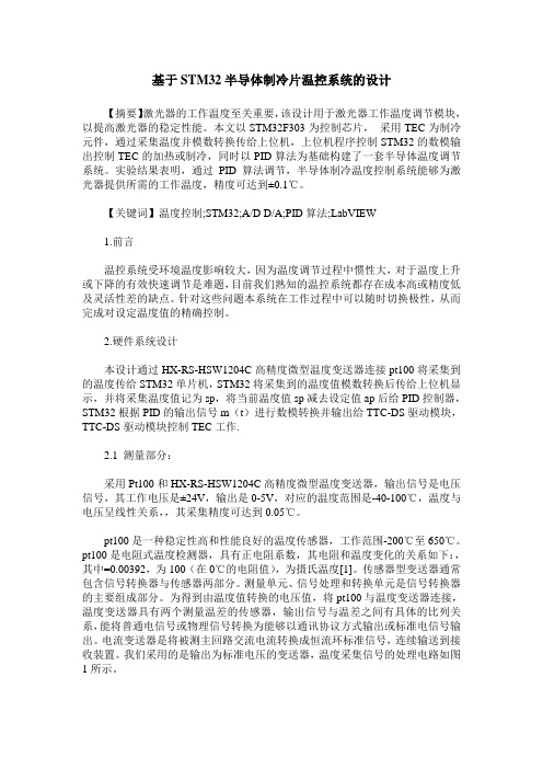
2.硬件系统设计本设计通过HX-RS-HSW1204C高精度微型温度变送器连接pt100将采集到的温度传给STM32单片机,STM32将采集到的温度值模数转换后传给上位机显示,并将采集温度值记为sp,将当前温度值sp减去设定值ap后给PID控制器,STM32根据PID的输出信号m(t)进行数模转换并输出给TTC-DS驱动模块,TTC-DS驱动模块控制TEC工作.2.1 测量部分:采用Pt100和HX-RS-HSW1204C高精度微型温度变送器,输出信号是电压信号,其工作电压是±24V,输出是0-5V,对应的温度范围是-40-100℃,温度与电压呈线性关系,,其采集精度可达到0.05℃。
pt100是一种稳定性高和性能良好的温度传感器,工作范围-200℃至650℃。
pt100是电阻式温度检测器,具有正电阻系数,其电阻和温度变化的关系如下:,其中=0.00392,为100(在0℃的电阻值),为摄氏温度[1]。
传感器型变送器通常包含信号转换器与传感器两部分。
基于STM32智能温控箱控制系统的设计

基于STM32智能温控箱控制系统的设计智能温控箱控制系统是一种常见的应用于工业控制领域的智能化控制系统。
本文基于STM32单片机,对智能温控箱控制系统进行设计和实现。
一、系统需求分析智能温控箱控制系统需要实现以下功能:1.对温度进行精确测量和控制;2.实时监测温度,并显示在控制面板上;3.能够根据设定的温度进行自动控制,实现温度稳定在设定值附近;4.通过人机界面(HMI)使用者可以对温度设定值、报警温度等进行设置和调整;5.当温度超过设定的报警温度时,能够及时报警;6.提供通讯接口,与上位机或其他设备进行通信,实现远程监控和控制。
二、系统硬件设计1.采用STM32单片机作为主控芯片,具有强大的计算和处理能力;2.温度传感器使用DS18B20数字温度传感器,可以实现对温度的高精度测量;3.控制面板采用LCD显示屏,用于显示温度和参数设置,并提供操作按键;4.报警部分使用蜂鸣器进行报警,并可以通过控制面板上的开关进行开启或关闭。
三、系统软件设计1.硬件初始化:初始化STM32芯片、温度传感器和控制面板;2.温度测量:通过DS18B20传感器读取温度值,并进行数字转换,得到实际温度值;3.温度控制:根据设定的温度值进行控制,通过PID算法控制温度稳定在设定范围内;4.参数设置:通过控制面板上的键盘输入,可以设置温度设定值、报警温度等参数;5.报警检测:检测当前温度是否超过设定的报警温度,若超过则触发报警;6.通讯接口:通过串口或其他通讯方式,实现与上位机或其他设备的数据传输和控制。
四、系统测试和验证搭建好硬件系统后,使用示波器等设备对系统进行测试和验证。
首先测试温度测量功能,将温度传感器放置在不同温度环境下,通过控制面板上的显示屏观察温度值是否准确。
然后测试温度控制功能,设定不同的温度值,观察系统是否能够控制温度稳定在设定范围内。
接着测试参数设置功能,通过控制面板上的键盘输入不同的参数值,并观察系统是否能够正确设置参数。
基于stm32的智能温湿度控制系统的设计与实现主要内容
基于stm32的智能温湿度控制系统的设计与实现主要内容基于STM32的智能温湿度控制系统的设计与实现主要涉及以下几个关键部分:1. 硬件设计:选择STM32作为主控制器,因为它具有强大的处理能力和丰富的外设接口。
温度传感器:例如DS18B20或LM35,用于测量环境温度。
湿度传感器:例如DHT11或SHT20,用于测量环境湿度。
微控制器与传感器的接口设计。
可能的输出设备:如LED、LCD或蜂鸣器。
电源管理:为系统提供稳定的电源。
2. 软件设计:使用C语言为STM32编写代码。
驱动程序:为传感器和输出设备编写驱动程序。
主程序:管理系统的整体运行,包括数据采集、处理和输出控制。
通信协议:如果系统需要与其他设备或网络通信,应实现相应的通信协议。
3. 数据处理:读取传感器数据并进行必要的处理。
根据温度和湿度设定值,决定是否进行控制动作。
4. 控制策略:根据采集的温度和湿度值,决定如何调整环境(例如,通过加热器、风扇或湿度发生器)。
控制策略可以根据应用的需要进行调整。
5. 系统测试与优化:在实际环境中测试系统的性能。
根据测试结果进行必要的优化和调整。
6. 安全与稳定性考虑:考虑系统的安全性,防止过热、过湿或其他可能的故障情况。
实现故障检测和安全关闭机制。
7. 用户界面与交互:如果需要,设计用户界面(如LCD显示、图形用户界面或手机APP)。
允许用户设置温度和湿度的阈值。
8. 系统集成与调试:将所有硬件和软件组件集成到一起。
进行系统调试,确保所有功能正常运行。
9. 文档与项目报告:编写详细的项目文档,包括设计说明、电路图、软件代码注释等。
编写项目报告,总结实现过程和结果。
10. 可能的扩展与改进:根据应用需求,添加更多的传感器或执行器。
使用WiFi或蓝牙技术实现远程控制。
集成AI或机器学习算法以优化控制策略。
基于STM32的智能温湿度控制系统是一个综合性的项目,涉及多个领域的知识和技术。
在设计过程中,需要综合考虑硬件、软件、传感器选择和控制策略等多个方面,以确保系统的稳定性和性能。
stm32f103的恒温室控制系统设计
stm32f103的恒温室控制系统设计
STM32F103恒温室控制系统的设计是基于STM32F103的ARM处理器,旨在实现对环境温度的恒温控制。
整个控制系
统包括软件程序、硬件电路及相关传感器。
由于STM32F103是一种性能优异的微控制器,因此具有良好
的外部性能,主要应用于电子产品的恒温控制。
首先,要设计出用于恒温控制的电路。
在这里,我们使用了PID控制电路,其中包括温度传感器、I/O接口和电源电路等,确保系统的稳
定性。
接着,我们编写了围绕STM32F103的控制程序,该程
序实现了通过温度传感器读取当前温度,并根据温度差调整加热装置,以保证恒温室内部温度恒定不变。
此外,我们还编写了围绕STM32F103的用户界面,用于方便
用户查看当前温度,设置所需的温度值并监控温度的变化。
同时,系统也支持将数据存储在SD卡上,以便可以随时查看和
分析温度变化的历史记录。
总而言之,我们设计的STM32F103恒温室控制系统具有以下
特点:1)恒温控制精度高;2)低功耗,提高系统的可靠性;3)数据存储,方便查看和分析数据;4)人性化的用户界面,方便用户操作。
同时,这一控制系统还可以用于其他用途,如净化室,仪器仪表等温度控制领域。
基于STM32的直流电机PID调速系统设计
基于STM32的直流电机PID调速系统设计一、引言直流电机调速系统是现代工业自动化系统中最常用的电机调速方式之一、它具有调速范围广、响应快、控制精度高等优点,被广泛应用于电力、机械、石化、轻工等领域。
本文将介绍基于STM32单片机的直流电机PID调速系统的设计。
二、系统设计直流电机PID调速系统主要由STM32单片机、直流电机、编码器、输入和输出接口电路等组成。
系统的设计流程如下:1.采集反馈信号设计中应通过编码器等方式采集到反馈信号,反应电机的转速。
采集到的脉冲信号经过处理后输入给STM32单片机。
2.设计PID算法PID调节器是一种经典的控制算法,由比例(P)、积分(I)和微分(D)三个部分组成,可以根据实际情况调整各个参数的大小。
PID算法的目标是根据反馈信号使电机达到期望的转速。
3.控制电机速度根据PID算法计算出的偏差值,通过调节电机的占空比,实现对电机速度的控制。
当偏差较大时,增大占空比以加速电机;当偏差较小时,减小占空比以减速电机。
4.界面设计与控制设计一个人机交互界面,通过该界面可以设置电机的期望转速以及其他参数。
通过输入接口电路将相应的信号输入给STM32单片机,实现对电机的远程控制。
5.系统保护在电机工作过程中,需要保护电机,防止出现过流、超速等问题。
设计一个保护系统,能够监测电机的工作状态,在出现异常情况时及时停止电机工作,避免损坏。
6.调试与优化对系统进行调试,通过实验和测试优化PID参数,以获得更好的控制效果。
三、系统实现系统实现时,首先需要进行硬件设计,包括STM32单片机的选型与外围电路设计,以及输入输出接口电路的设计。
根据实际情况选择合适的编码器和直流电机。
接着,编写相应的软件代码。
根据系统设计流程中所述,编写STM32单片机的控制程序,包括采集反馈信号、PID算法实现、控制电机速度等。
最后,进行系统调试与优化。
根据系统的实际情况,调试PID参数,通过实验和测试验证系统的性能,并进行优化,以实现较好的控制效果。
基于STM32单片机PID温控学习系统设计
• 155•本设计采用STM32F103单片机为主控芯片,采用数字型温度传感器DS18B20为温度检测器,采用3.5寸触摸液晶屏显示温度变化曲线以及PID相关参数设置,采用半导体制冷片对散热片加热,散热风扇对散热片散热,系统会根据所设参数控制半导体制冷片和散热风扇的运作。
前言:在工程实际中,应用最为广泛的调节器控制规律为比例、积分、微分控制,简称PID 控制,又称PID 调节。
它以其结构简单、稳定性好、工作可靠、调整方便而成为工业控制的主要技术之一。
温度控制在生活以及工业制造中都发挥着必不可少的作用,工业需要温度测控系统来监控温度,生活中也离不开温度测控系统为我们及时提供温度信息。
虽然只是一个简单的温度控制,却包含了许多知识的运用。
PID 实指“比例proportional ”、“积分integral ”、“微分derivative ”,这三项构成PID 基本要素。
P 代表控制系统的响应速度,越大,响应越快;I 用来积累过去时间内的误差,修正P 无法达到的期望姿态值(静差);D 加强对机体变化的快速响应。
对P 有抑制作用。
PID 各参数的整定需要综合考虑控制系统的各个方面,才能达到最佳效果。
1.总体方案设计图1 系统总体功能框图系统主要功能:(1)触摸液晶屏一方面用于温度恒定值、散热系数、PID 相关参数、温度曲线显示精度的输入;另一方面用于显示所设置的参数、被加热元件散热片的温度随时间变化曲线、当前时间等。
(2)单片机根据设置的参数通过12V 驱动模块控制半导体制冷片实际功率,达到控制半导体制冷片散热片的加热快慢。
(3)单片机根据设置的散热系数通过12V 驱动模块控制散热风扇转速,从而模拟不同情形的降温速度。
(4)单片机通过串口实时发送温度、半导体制冷片加热系数、散热风扇转速。
便于上位机对数据保存和处理。
2.硬件部分2.1 主控芯片单片机作为整个系统的核心部件,决定整个系统的性能。
单片机需要完成的主要功能有:(1)读取温度传感器所采集的温度值。
- 1、下载文档前请自行甄别文档内容的完整性,平台不提供额外的编辑、内容补充、找答案等附加服务。
- 2、"仅部分预览"的文档,不可在线预览部分如存在完整性等问题,可反馈申请退款(可完整预览的文档不适用该条件!)。
- 3、如文档侵犯您的权益,请联系客服反馈,我们会尽快为您处理(人工客服工作时间:9:00-18:30)。
成绩评定基于PID的STM32恒温控制系统设计摘要研究基于STM32单片机和温湿度传感器的恒温智能控制系统。
温度具有时变性、非线性和多变量耦合的特点。
在温度控制过程中,温度的检测往往滞后于温度的调控,从而会引起温度控制系统的温度出现超调、温度振荡的现象。
在设计中提出了基于增量式PID算法控制温度的模型,系统采用低功耗的STM32作为主控芯片、DHT11数字式温度传感器和半导体温度调节器。
实验结果表明,该系统能够有效地维持系统地恒温状态。
通过将数字PID算法和STM32单片机结合使用,整个控制系统的溫度控制精度也提高了,不仅仅满足了对温度控制的要求,而且还可以应用到对其他变量的控制过程中。
所以,在该温度控制系统的设计中,运用单片机STM32进行数字PID运算能充分发挥软件系统的灵活性,具有控制方便、简单和灵活性大等优点。
关键词:STM32,PID算法,恒温控制,DHT111绪论温度控制系统具有滞后性,时变性和非线性的特点。
无法建立精准的数学模型,因此使用常规的线性控制理论无法达到满意的控制效果。
在嵌入式温度控制系统中的关键是温度的测量、温度的控制和温度的保持,温度是工业控制对象中主要的被控参数之一。
因此,嵌入式要对温度的测量则是对温度进行有效及准确的测量,并且能够在工业生产中得广泛的应用,尤其在机械制造、电力工程化工生产、冶金工业等重要工业领域中,担负着重要的测量任务。
在日常工作和生活中,也被广泛应用于空调器、电加热器等各种室温测量及工业设备的温度测量。
但温度是一个模拟量,需要采用适当的技术和元件,将模拟的温度量转化为数字量,才生使用计算机进行相应的处理。
2 设计方案为了对于交流负载做到温度精确,升温采用控制双向可控硅导通角度进行升温控制。
降温采用PWM电压控制,因为当前降温采用制冷片,风扇等降温手段,采用直流电压供电方式,选用PWM控制使降温更加精确。
温度采集选用温度传感器DHT11,好处为可做到高精度,整体框图如图1所示。
图1 系统框图3硬件设计3.1 DHT11温度传感器DHT11数字温湿度传感器是一款含有已校准数字信号输出的温湿度复合传感器。
它应用专用的数字模块采集技术和温湿度传感技术,确保产品具有枀高的可靠性与卓越的长期稳定性。
传感器包括一个电阻式感湿元件和一个NTC测温元件,并与一个高性能8位单片机相连接。
DHT11电路图如图2所示。
图2 HT11电路图DHT11是通过单总线与微处理器通讯,只需要一根线,一次传送40位数据,高位先出。
数据格式:8bit湿度整数数据+ 8bit湿度小数数据+ 8bint温度整数数据+ 8bit温度小数数据+ 8bit校验位校验算法:将湿度、温度的整数小数累加,只保留低8位。
微处理器(M0)与DHT11通信约定:主从结构,DHT11为从机,M0作为主机,只有主机呼叫从机,从机才能应答。
详细流程:M0发送起始信号-> DHT响应信号-> DHT通知M0准备接受信号-> DHT发送准备好的数据-> DHT结束信号-> DHT内部重测环境温湿度数据并记录数据等待下一次M0的起始信号。
由流程可知,每一次M0获取的数据总是DHT上一次采集的数据,要想得到实时的数据,连续两次获取即可,官方不建议连续多次读取DHT,每次读取的间隔时间大于5秒就足够获取到准确的数据,上电时DHT需要1S的时间稳定。
3.2LCD屏幕显示TFT-LCD 又叫做薄膜晶体管液晶显示器,其管脚图如图3所示,其管脚在STM32F103中有相应的管脚对应。
常用的液晶屏接口很多种,8 位、9 位、16位、18 位都有。
而常用的通信模式呢,主要有6800 模式和8080 模式两种,今天呢,我们来讲的是8080 模式。
如果大家接触过LCD1602 或者LCD12864 等,那么就会发现8080 模式的时序呢,其实跟LCD1602 或者LCD12864 的读写时序是差不多的。
8080 接口有 5 条基本的控制线和多条数据线,数据线的数量主要看液晶屏使用的是几位模式,有8 根、9 根、16 根、18 根四种类型。
图3 LCD引脚图3.3 STM32单片机在STM32F105和STM32F107互连型系列微控制器之前,意法半导体已经推出STM32基本型系列、增强型系列、USB基本型系列、互补型系列;新系列产品沿用增强型系列的72MHz处理频率。
内存包括64KB到256KB闪存和20KB到64KB嵌入式SRAM。
新系列采用LQFP64、LQFP100和LFBGA100三种封装,不同的封装保持引脚排列一致性,结合STM32平台的设计理念,开发人员通过选择产品可重新优化功能、存储器、性能和引脚数量,以最小的硬件变化来满足个性化的应用需求。
内核:ARM32位Cortex-M3 CPU,最高工作频率72MHz,1.25DMIPS/MHz。
单周期乘法和硬件除法。
存储器:片上集成32-512KB的Flash存储器。
6-64KB的SRAM存储器。
时钟、复位和电源管理:2.0-3.6V的电源供电和I/O接口的驱动电压。
上电复位(POR)、掉电复位(PDR)和可编程的电压探测器(PVD)。
4-16MHz的晶振。
内嵌出厂前调校的8MHz RC振荡电路。
内部40 kHz的RC振荡电路。
用于CPU时钟的PLL。
带校准用于RTC的32kHz的晶振。
低功耗:3种低功耗模式:休眠,停止,待机模式。
为RTC和备份寄存器供电的VBAT。
调试模式:串行调试(SWD)和JTAG接口。
DMA:12通道DMA控制器。
支持的外设:定时器,ADC,DAC,SPI,IIC和UART。
3个12位的us级的A/D转换器(16通道):A/D测量范围:0-3.6V。
双采样和保持能力。
片上集成一个温度传感器。
2通道12位D/A转换器:STM32F103xC,STM32F103xD,STM32F103xE独有。
最多高达112个的快速I/O端口:根据型号的不同,有26,37,51,80,和112的I/O端口,所有的端口都可以映射到16个外部中断向量。
除了模拟输入,所有的都可以接受5V以内的输入。
最多多达11个定时器:4个16位定时器,每个定时器有4个IC/OC/PWM或者脉冲计数器。
2个16位的6通道高级控制定时器:最多6个通道可用于PWM输出。
2个看门狗定时器(独立看门狗和窗口看门狗)。
Systick定时器:24位倒计数器。
2个16位基本定时器用于驱动DAC。
最多多达13个通信接口:2个IIC接口(SMBus/PMBus)。
5个USART接口(ISO7816接口,LIN,IrDA兼容,调试控制)。
3个SPI接口(18 Mbit/s),两个和IIS复用。
CAN 接口(2.0B)。
USB 2.0全速接口。
SDIO接口。
ECOPACK封装:STM32F103xx系列微控制器采用ECOPACK封装形式。
4 软件设计4.1 软件流程图写出软件流程图,并附加文字说明。
本次软件的编写是在keil5上进行,界面如图X,并在编写后生成.Hex文件,然后用烧写软件FlyMcu(界面如图X)将.Hex文件烧写在开发版上,流程如图X。
图X keil5软件界面图X 烧写流程图图X 烧写软件本程序软件功能是使用DHT11温湿度检测模块检测温湿度,将检测到的温湿度送到STM32单片机,和单片机的摄入设定值进行比较,当检测温度高于设定值时,风扇开启,同时可以用按键去查看LCD屏幕上的温湿度值及风扇转速,程序结构如图X。
图X 程序功能框架图4.2 软件程序主程序如下:#include "main.h"#include "lcd.h"#include "key.h"#include "delay.h"#include "zi.h"extern const unsigned char gImage_111[153600];int main(void){static u8 key;u8 yd;Delay_Init();//嘀嗒时钟延时初始化Led_Init(); //LED灯初始化Beep_Init();//蜂鸣器初始化Key_Init(); //按键初始化Uart_Init(115200);//串口初始化//定时器3 PWM模式1初始化--周期1ms,占空比50%TIM3_PWMConfig(1000,72,500);LCD_Init();//LCD初始化//定时器4初始化--定时时间为1秒TIM4_Config(10000,72);//LCD显示Draw_Text_8_16_Str(50,50,WHITE,BLACK,"姓名学号");Draw_Text_8_16_Str(50,70,WHITE,BLACK,"李燕辉09");Draw_Text_8_16_Str(50,90,WHITE,BLACK,"孟舒展47");Draw_Text_8_16_Str(50,110,WHITE,BLACK,"王义涛46");while(1){key = Get_Key_Val();if(key){yd = key;}switch (yd){case 1: Paint_Bmp(0,0,240,320,gImage_111); break;case 2: PID_Ctrl(DHT11_ShowTAndH());break;case 3: drawpidline(0x1111);Draw_Text_8_16_Str(50,50,RED,BLACK,"温湿度机转速"); break; // drawpidline(0x1111);case 4 : LCD_Clear(WHITE); break;default : ;}}}5 实物调试与结果在调试时我们也是遇到了很多问题,在刚开始没有缓存按键导致数据无法传递,在显示温度时发现温度稳定在某一数值保持不变,经程序检查发现将按键的值缓存到寄存器中进行连续发送,此问题解决。
在显示图片和文字时发现显示效果不理想,图片模糊、字体乱码,排除问题时发现是字体取模方式以及图片格式不对,将文字横向取模调整成纵向取模和图片格式改成.jpg后再次显示,效果良好。
最终调试结果如图X,图X,图X,图X,图X,图X 上电初始图图X 清屏图温湿度显示及转速波形温度低于设定值时风扇停止转动总结本次实训持续两周左右,在这期间我们对更高一级的单片机STM32的认知从无到有,学习了这种单片机的编程思路,不同于我们以前学的51单片机,这种单片机功能更强大,编程也更繁琐,应用也更广泛,每使用一个模块,都要对其进行时钟和寄存器的配置,这样的设计更符合低功耗的要求,更适合社会的发展趋势,这次实训也让我们学到很多关于项目的东西,在此次实训期间,我们学会了如何把所学的知识应用在实践中,让实践与理论相结合,真正做到学以致用。