手动蝶阀使用说明书
EUROSTOP手动蝶阀说明书
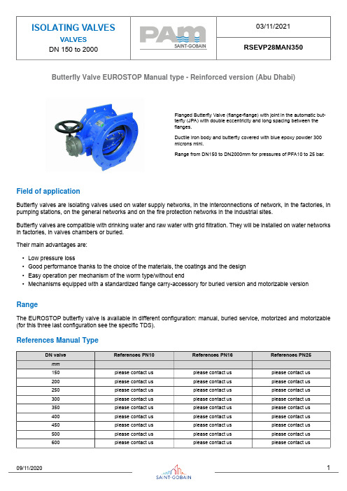
Butterfly Valve EUROSTOP Manual type - Reinforced version (Abu Dhabi)Flanged Butterfly Valve (flange-flange) with joint in the automatic but-terfly (JPA) with double eccentricity and long spacing between theflanges.Ductile iron body and butterfly covered with blue epoxy powder 300microns mini.Range from DN150 to DN2000mm for pressures of PFA10 to 25 bar.Field of applicationButterfly valves are isolating valves used on water supply networks, in the interconnections of network, in the factories, in pumping stations, on the general networks and on the fire protection networks in the industrial sites.Butterfly valves are compatible with drinking water and raw water with grid filtration. They will be installed on water networks in factories, in valves chambers or buried.Their main advantages are:•Low pressure loss•Good performance thanks to the choice of the materials, the coatings and the design•Easy operation per mechanism of the worm type/without end•Mechanisms equipped with a standardized flange carry-accessory for buried version and motorizable version RangeThe EUROSTOP butterfly valve is available in different configuration: manual, buried service, motorized and motorizable (for this three last configuration see the specific TDS).References Manual TypeMaterial and coatingValve equipped with 4 holes for the lifting of the valves DN>600. The gear box of the mechanism is in ductile iron FGS 400-15 type.Dimensions and massManual Version PN10Manual Version PN16Manual Version PN25Gearbox type and handwheel Manual type PN10Manual type PN16Manual type PN25Applicable StandardsHydraulic testEvery single butterfly valve is subjected to hydraulic final test with the purpose of verifying the accordance with the prescrip-tions ISO 5208:•Body test at 1,5 time the PFA (open valve);•Seat test at 1,1 time the PFA (closed valve).Product test•Control of manoeuvre torque (MOT and mST) as defined in the EN1074•Control of coating: test of thickness, holiday test, impact test, MIBK testConformity to the standardsProduct:•EN 1074 – 1 and 2•EN 593•ISO 10631Plant test:•ISO 5208Flanges dimension:•ISO 5752 series 14Flanges drilling:•EN 1092-2•ISO 7005-2Suitability for potable water:•Italian CM 102 of 02/12/78•Conformity to foreign norms: KTW (Germany), WRC (U.K.), ACS (France)MarkingOn the body like EN19:•Nominal diameter in mm (DN);•Nominal pressure in bar (PN);•Type of ductile iron;•Manufacturer’s logo;•Model code;•Fusion date.On the label like EN19:•Nominal diameter in mm (DN);•Nominal pressure in bar (PN);•Maximum operating pressure (PFA);•Closing direction;•Model code;•Manufacturing order, Order confirmation;•Manufacturer’s logo.On the disc:•Nominal diameter in mm (DN);•Nominal pressure in bar (PN);•Type of ductile iron;•Manufacturer’s logo;•Model code.The marking of the valves manufactured by Saint-Gobain refers to the EN 1074-2 and EN 19 international standards. Markings are either integral markings, cast in the body, or markings made on plates, securely fixed to the body, in accordance with the EN 19 standard specifications.Valve selectionThe butterfly valves are generally used as isolating devices type on/off. In some particular case, in which there’s low differ-ences of pressure and low flow rate variation can be used like regulating devices, considering the hydraulic parameters necessary to avoid the cavitation risk.To do the right dimensioning of butterfly valve it’s necessary to know the followings parameters:•Upstream hydrostatic pressure (that is the hydrostatic pressure with valve in closed position)•The maximum speed in water pipe (generally expressed in l/s) or the nominal diameter and the project flow rate from which it is gained the speed V=Q/AMoreover it’s necessary to control that the maximum speed in water pipe have to be equal or inferior to 5m/s, and the exercise temperature have to be between 0°C and 40 °C.Hydraulic featuresThe head loss Δh are variable in function of valve open degree and can be calculated with the following expression:with Δh = head loss (m), ζ = head loss coefficient (dimensional), v = nominal speed (m/s), g = 9,81 (m/s²)The head loss coefficient can be estimated from this diagram:Determinates the head loss Δh it’s possible to calculate the flow rate Q in m3/h with the following expression (the same expression can be used to, having the project flow rate Q, to determinate the head loss Δh without using the head loss coefficient):in which 10,2 is a corrective factor in meters, and Kv is the flow rate coefficient in m3/h, determinable from the following diagram in function of valve open degree:Example: Valve DN600 mm - Δh = 3 mFrom the diagram with valve open to 100% the coefficient Kv is 20000 m3/h. Using this date in the flow rate expression:Otherwise it’s possible to calculate the head loss with valve completely open, having the project flow rate Q, in function of DN, using the following diagram:CavitationIf the butterfly valve is used only like isolating device there’s not cavitation risk.In the particular case in which it’s used like regulating device, this can be possible only respecting the following parameters:•The valve open degree have to be between 30° and 90° (valve completely open)•The downstream pressure P2 have to be: P2 ≥ 0,7 .P1 - 2,8 with P1 upstream pressure.Instructions for useStorageThe butterfly valve will have to be held (if possible) in covered places, the most possible protected from the sun (maximum allowable temperature 70°C in accordance to EN 1074), from the rain and generally from the atmospheric agents. Moreover it will have to be avoided that the seal of the same air valves come to contact with powder or earth.InstallationThe butterfly valves are generally installed with retaining ring mounted in the opposite way respect to the direction of flow rate to permit the substitution of gasket without dismounting the valve from pipeline. In any case it is possible to install the butterfly valve with flow rate in opposite direction and also, if required, in vertical position. We recommend to install the butterfly with the operating device on the hydraulic right side of pipeline.It’s possible to install the butterfly valve both in chamber valve that underground (choosing the right configuration).We recommend to insert a dismounting joint for the operation of maintenance.MaintenanceThe butterfly valve does not require a particular maintenance, all parts subjected to wear are perfectly auto-lubricating. In any case, if for a long time will be not used, it is necessary to evaluate the functioning of valve doing (at least one time for year) some manoeuvre of opening-closing.All the maintenance operation have to be do after the total emptying of pipeline (no flow rate and pressure) to avoid every risk to the people during this operation.In presence of particularly exercise condition or damage due to external cause, it will be necessary some maintenance operation. In this case the particular shape of EUROSTOP butterfly valve permits the simple gasket substitution without the dismounting of valve from pipeline (if the dismounting joint is present).AccessoriesTo adapt the butterfly valves to the different exercise and installation conditions required, they can be equipped with particular accessories used in combination with control devices: please refer to data sheet for accessories.The technical features in this document are not contractual and can be changed without preliminary notification due to the continuous technical progress of product.。
蝶阀使用说明书

蝶阀使用说明书1.范围本说明书包括了公称通径DN50mm~1600mm(2”~64”)、公称压力PN1.0MPa~4.0MPa(ANSI CLASS150~300)法兰和对夹连接的手动、齿轮传动、电动和气动操作蝶阀。
2.用途2.1主要用于开启或关闭管道和设备的介质用,作调节、截流和止回使用。
2.2根据介质选用阀门的材质。
2.2.1碳钢阀门适用于水、蒸汽、油品等介质。
2.2.2不锈钢阀门适用于腐蚀性介质。
2.2.3铸铁阀门适用于水、气体介质。
2.3适用温度取决于阀座的材质。
PTFE(聚四氟乙烯)≤130℃不锈钢+复合体≤425℃橡胶≤85℃3.结构3.1蝶阀基本结构见图13.2易损件填料采用聚四氟乙烯或柔性石墨,密封可靠。
4.操作4.1手动操作阀门采用手柄或齿轮传动装置、电动或气动蝶阀由电动装置或气动装置驱动,使蝶板旋转90°开启或关闭阀门。
4.2对于手动(包括驱动装置的手轮)或扳手操作的蝶阀,除订货合同另有规定外,当面向手轮或扳手时,顺时针方向转动手轮或扳手阀门应为关。
4.3电动、气动蝶阀的开启、关闭指示由电动装置、气动装置上的位置指示器标识。
5.保管、保养、安装和使用5.1阀门应存放在干燥,通风的室内,阀门通道两端应堵塞。
5.2长期存放的阀门应定期检查,清除污物。
应特别注意密封面的清洁,防密封面的损坏。
5.3安装前应仔细核对阀门标志是否与使用要求相符。
5.4安装前应检查阀门通道和密封面,如有污垢,应使用清洁布擦拭干净。
5.5安装前检查填料是否压紧,应确保填料的密封性,同时不应妨碍阀杆的转动。
5.6安装时拧紧连接螺栓的拧紧力应均匀合适。
5.7本蝶阀可以安装水平、垂直的管道上,安装位置应保证使用维修更换方便。
5.8手动阀门在开启或关闭操作时,应使用手柄开、关,不得借用辅助杠杆或其它工具。
5.9阀门使用应定期检查,检查密封面有无磨损及垫片填料。
若损坏失效,应及时修理或更换。
5.10电动、气动阀门的传动装置,其保管、保养、安装和使用,请见“阀门电动装置使用说明书”及“阀门气动装置使用说明书”。
蝶阀产品使用说明书
蝶阀产品使用说明书
1 概述
1.1 主要用途及适用规范:
本阀门主要用于石油、天然气、油品、化工、冶金、城建及一般工业管道上作为切断装置。
1.2 品种及规格:
对夹式蝶阀,压力等级10MPa、通径DN200
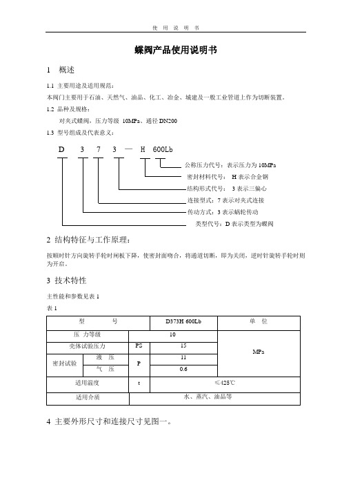
1.3 型号组成及代表意义:
D 3 7 3 — H 600Lb
公称压力代号:表示压力为10MPa
密封材料代号:H表示合金钢
结构形式代号:3表示三偏心
连接型式:7表示对夹式连接
传动方式:3表示蜗轮传动
类型代号:D表示类型为蝶阀
2 结构特征与工作原理:
按顺时针方向旋转手轮时闸板下降,使密封面吻合,将通道切断,即为关闭,逆时针旋转手轮时则为开启。
3 技术特性
主性能和参数见表1
表1
4 主要外形尺寸和连接尺寸见图一。
5 主要零件的材料
D373H-600Lb的主要零件材料见表2
表2
6 保管、使用和安装
6.1本阀门通道两端须堵密封盖,存放有干燥通风的室内。
长期存放,应经常检查,防止锈蚀6.2安装前,应将阀门清洗干净,并消除在运输过程中可能造成的缺陷。
6.3安装前,必须仔细核对阀门上的标志和铭牌是否符合使用要求。
6.4本阀门应安装在水平或垂直管道上的直立或侧卧位置,并便于检修和操作。
6.5本阀门在运行时应全开或全闭,不能作节流用,以免密封面受冲刷而加速磨损。
6.6传动部位应保持清洁,应定期加注润滑油。
7 故障分析与排除方法见表3
表3
图一。
蝶阀使用说明书
蝶阀使用说明书1.用途:蝶阀是常用的截断阀之一,主要用来接通和截断管道中的介质,也可以适当起调节介质流量的作用。
2.产品描述2.1蝶阀是随阀杆一起转动的蝶板作启闭件,用以实现阀门的开启,关闭与调节。
2.2这种阀门的设计和制造标准为GB/T12238。
2.3安装图纸、适用工作温度,工作压力和主要材质都在样本中有详细说明。
3.储存、维修、安装和操作。
3.1储存和维修3.1.1阀门应储存在室内干燥并且通风的环境中。
两端应用盖子封住。
3.1.2阀门储存很长一段时间后应进行定期检查和清洁。
尤其要清洁密封座和蝶板以保护密封表层不受影响。
3.1.3如果储存时间超过12个月,阀门应该重新检测结构和性能。
同时进行记录。
3.1.4阀门在安装以后要定期进行检修。
检修内容如下:(1) 密封座(2) O型圈(3) 阀杆和填料(4) 阀体和蝶板上的锈斑3.2安装3.2.1保证阀门标志(型号、公称通径、公称压力、材质、)在安装前符合管道系统的要求。
3.2.2安装前仔细检测通道和密封面;任何污垢都应该清除。
3.2.3阀门应该安装在便于检测和操作的地方。
最好的位置是在立式安装。
3.2.4不适合安装在工作压力较大的环境,避免阀座损坏。
3.2.5应避免来自于支撑物、附件、管道等高压。
3.2.6安装后,在进行管道系统压力检测时,阀门应该完全开启。
3.2.7如果管道有足够的强度承受阀门重量和操作力矩,就不需用支撑点。
否则就需要。
3.3使用和操作3.3.1 在介质高速流动时,阀门必须完全开或全闭式,以避免密封面损伤。
3.3.2 当开启或关闭阀门时,可用其它工具代替手轮。
3.3.3在工作温度下,工作压力不应该超过最大允许的工作压力允许的最大工作压力为:PN10;温度范围是–10℃≤T≤100℃。
3.3.4在工作温度下,确保瞬间压力小于最大允许工作压力的1.1倍。
3.3.5在工作温度下,在管道中安装安全装置来防止工作压力超过最大允许压力值。
3.3.6禁止在运输\安装操作中撞坏阀门。
KD741液控蝶阀说明书
KD741液控蝶阀说明书泵站型液控蝶阀使⽤说明书⼀、主要性能特点、⽤途及适⽤范围本产品为新型的⽔泵出⼝重锤式液压控制蝶阀,全称为希斯威系列泵站型⾃动保压重锤式液控蝶阀或希斯威系列泵站型⾃动保压重锤式液控⽌回蝶阀,分普通型、防泥沙和防海⽔型三种,防泥沙型液控蝶阀⽤于⽔中含泥沙等杂质较多的泵站,防海⽔型液控蝶阀⽤于介质为海⽔或河⽔中混有海⽔等⼯况的泵站。
希斯威系列泵站型液控蝶阀是⽔泵站中管线系统截断或接通介质的理想设备,适⽤于装在⽔泵的出⼝处,作为⽔泵机组的主控阀门和安全阀,具有以下功能:1、本蝶阀根据启、停泵的⽔⼒过渡过程理论进⾏设计,采⽤分阶段开、关阀,其开阀、快关、慢关时间及快慢关转换⾓度等参数均可根据需要现场整定,可满⾜电⼚、⾃来⽔⼚、排灌⼯程等给排⽔泵站不同⼯况的要求。
2、本蝶阀在⽔泵机组正常启动时,可根据⽔泵机组要求按预先调定的不同程序启动,从功能。
当⽔泵为离⼼泵⼯况时,可先启泵后开阀,实现⽔泵关阀(造压)启动;当⽔泵为轴流泵或斜/混流泵⼯况时,可先开阀(全开或部分开度)后启泵。
3、机组正常停机时,本蝶阀可根据机组的要求按预先调定的不同程序分快慢两阶段关闭阀门,起到截⽌和⽌回的作⽤,当管道不发⽣⽔柱中断时,可有效地防⽌停泵时⽔泵反转、系统失⽔和管⽹压⼒升⾼,从⽽消除⽔锤危害、控制⽔泵反转,起到保护⽔泵机组和管⽹安全的作⽤。
当⽔泵为离⼼泵⼯况时,可实现先关阀(部分开度)后停泵;当⽔泵为轴流泵或斜/混流泵⼯况时,可实现先关阀(部分开度)后停泵或泵阀同时停的功能。
4、当机组紧急停机或电⽹突然失电等⾮常⼯况时,本阀将具有下述两种关阀形式之⼀,故请在泵站设计选型及产品订货合同中注明:(a)、正作⽤电磁阀型:在蝶阀开启情况下,电磁阀常带电,当电磁阀失电时,蝶阀关闭,⼀般适⽤于⽆稳定控制电源的⽔⼚采⽤。
阀门在失电的同时将⾃动按照预先调定的程序分快慢两阶段⾃动关闭,直⾄全关;(电⼚三期7、8、9号循环泵属正作⽤)(b)、反作⽤电磁阀型:在蝶阀开启时,电磁阀不带电,当电磁阀得电时,蝶阀关闭,需稳定的控制电源,⼀般适⽤于电⼚采⽤。
唯特利蝶阀(FireLock Butterfly Valve)说明书

如需产品安装、维护或支持信息,请参考本文档末的信息。
1.0 产品描述供货尺寸• 2 – 8"/DN50 – DN200.管道材料• 碳钢,壁厚10、壁厚40。
如需使用其他材料,请与 Victaulic (唯特利)联系。
最大工作压力• 经 cULus 认证、LPCB 认证、FM 和 VdS 批准可在不超过 300 psi/2068 kPa /20 bar 的压力下使用。
应用• 蝶阀带有经认证的全天候执行机构外壳,适合室内或室外使用。
• 设计仅用于消防应用场合。
• 设计用于闭合状态监控。
在正常工作条件下,该阀门是关闭的。
• 专用于管端符合Victaulic OGS 沟槽管道系统规格的管道和Victaulic (唯特利)产品(有关参考材料,请参见7.0节)。
适用的管端连接• Victaulic (唯特利)传统沟槽系统(OGS )标准沟槽。
2.0 认证/列名G410013LPS 1185:Issue 3.1Cert/LPCB Ref. 104j/01846a/01FireLock ™ 蝶阀带全天候执行机构的 707C 系列 – 监控常闭10.75-CHI2.1 认证/列名707C 系列3.0 规格 – 材料阀体:符合ASTM A-536之65-45-12等级要求的球墨铸铁端面,2 – 6英寸/DN50 – DN150:符合ASTM A-536之65-45-12等级要求的球墨铸铁密封定位器,8 英寸/DN200:符合ASTM A-536之65-45-12等级要求的球墨铸铁阀体涂层:黑色醇酸树脂漆阀板:符合ASTM A-536之65-45-12等级要求的球墨铸铁,带符合ASTM B-733标准要求的化学镀镍涂层阀座:三元乙丙橡胶 (EPDM)阀杆:符合ASTM A-582标准要求的416不锈钢阀杆密封套:C36000黄铜轴承:内衬四氟乙烯的不锈钢阀杆密封材料:三元乙丙橡胶 (EPDM)阀杆定位环:碳钢执行机构: 2 – 8"/DN50 – DN150 :位于钢质导向螺杆上的可移动黄酮或青铜螺母,球墨铸铁外壳注• 可选配½英寸/15毫米锥螺纹孔。
良工蝶阀 安装使用说明
-3-
安装使用与维修
一、运输与贮存
1、蝶阀在搬运过程中,应对两密封面加以保护,以防止碰伤。 2、蝶阀应在防雨、防尘、干燥处存放,使蝶板处于开启 5°-10°状态,并加以覆盖,防止杂物进入
密封面。
二、安装使用注意事项
1、安装前应该对蝶阀规格、压力、温度、耐腐性是否满足使用要求。应检查各部零件是否损坏或松动。 2、本蝶阀可安装在任意角度的管道上,应关闭安装为宜;焊接管道法兰时应将阀门密封口用板档住以
80 114 445 97 200 160 132 20 8-18 200 160 132 20 8-18 200 160 132 24 8-18
100 127 485 107 220 180 156 22 8-18 220 180 156 22 8-18 235 190 156 24 8-22
125 140 560 122 250 210 184 22 8-18 250 210 184 22 8-18 270 220 184 26 8-26
150 140 632 198 285 240 211 24 8-22 285 240 211 24 8-22 300 250 211 28 8-26
200 152 754 236 340 295 266 24 8-22 340 295 266 24 12-22 360 310 274 30 12-26
工字牌
蝶阀安装使用说明书
(金属硬密封)
上海良工阀门厂有限公司
SHANGHAI LIANGGONG VALVE FACTORY CO., LTD
概述:
随着科学技术的进步和产品的更新,工业阀门的需求已有显著的变化。本蝶阀广泛用于电站供热系 统和催化裂化主风机管道系统、钢铁、冶金、石化、电力炼油、矿山等工业管道上作切断和调节流量用。
KIESELMANN蝶阀和球阀手册说明书
KIESELMANNF L U I D P R O C E S SG R O U PMANUAL LEVEROur ergonomic thermal protection handle in the plasticblack/red design. Other colours are available on request.A stainless steel handle is also available.2ContentINTRODUCTION 4Valve technology:The standard and the ballBUTTERFLY VALVES 6Butterfly valves, intermediate flangebutterfly and three-way butterfly valvesLEAKAGE BUTTERFLY VALVES 8BALL VALVES 10Ball valves, three-way ball valves,rinsing connection and heating jacketCONTROL AND SWITCHING 12Manual levers, actuators, control headsand positioners34Save space and costs: KIESELMANN butterfly valves are the space-saving, inexpensive solution. Our ball valves The standard and the ballKIESELMANN VALVE TECHNOLOGY5 HAND LEVERBUTTERFL Y VALVE BALL VALVE THREE-WAY BUTTERFL Y VALVEPNEUMATIC ACTUATORWITH POSITION INDICATORAND SENSOR MOUNTINGPNEUMATIC ACTUATORWITH CONTROL HEAD/POSITIONER KIESELMANN stainless steel valves:Highest quality in dimensional accuracy and surface finish. All sealing elements used havethe necessary approvals for the food industry.The modular design of our valves allows quickand easy switching from a manual lever to apneumatic actuator with sensors or control head.6 |BUTTERFLY VALVESKIESELMANN butterfly valves are the space-saving solution for shutting off product flows in process systems such as on panels and tanks in a hygienic and inexpensive way. They are also available as intermediate flange butterfly valves as well as numerous other connection variants, such as welding and threaded ends. We manufacture all valves at our headquarters in Knittlingen.The space-saving solutionBUTTERFLY VALVESBUTTERFLY VALVES | 7The sealing elements used all have suitability certifications for use in the food industry.The ergonomic thermal protection handle of our butterfly valves is available with a 90° lock oroptionally with shift limit. Alternatively, these valves are also available with a stainless steel handle.Automatically cost-effectiveAutomation is also possible with this cost-effective valve solution. Our modular system makes it possible to quickly and inexpensively convert the manual lever to a pneumatic actuator without disconnecting any pipeline connections to the pipeline. The actuators are available with sensors or control head KI-TOP.Intermediate flange butterfly valve with k-flex seal to the flange closures> E rgonomic thermal protection handle, 90° lock or optional shift limit > S tandard or shortened handle design, fiberglass (reinforced plastic material), available in your choice of colours or stainless steel > Vacuum insert suitable> Easy installation, many connection options> Three-way butterfly valves with switching combinations > Service-friendly intermediate flange design > Tailor-made and long-term spare parts supplyADVANTAGESPlain bearingEnd plugLocking discPlain bearing*V alves with flanged connection PN10 may only be operated with an operating pressure of up to 10 bar.**Nominal size only available as intermediate flange butterfly valves.DOCUMENTATIONHere you can download all important data, information and certificates about our products as PDF files.8 | LEAKAGE BUTTERFLY VALVESKIESELMANN leakage butterfly valves provide increased process security. Mix-proof separation of different media is ensured via the dual-sealing, one-piece valve disc. Runoff-drains allow direct detection of any leaks. Identified, eliminated: Thanks to our maintenance-friend-ly valve design. The drains can also function as rinse connections, ideal for Cleaning-in-Place (CIP) processes.Secure and adaptiveLEAKAGE BUTTERFLY VALVESLEAKAGE BUTTERFLY VALVES | 9> Cost-effective leakage protection > Sealing materials EPDM, HNBR > H ygienically safe due to easy cleaning of the leakage chamber, CIP appropriate > E asy-to-maintain design with just one sealing elementKIESELMANN leakage butterfly valves are generally available in intermediate flange version.This design and the split housing allow the seals to be easily and quickly replaced.Functional principleWhen closed, the butterfly valve with a tandem seal ensures that different media remain separated without leaking.Any leaks at the butterfly valve seal flow without pressure through the leakage drain port at the leakage outlets.The leakage chamber can be integrated into a CIP circuit via the rinsing connections. For demanding products, we generally recommend cleaning theleakage chamber.ADVANTAGESLeakage drainLeakage drain ring-groovePlain bearingPRODUCT VIDEOVisit us on YouTube. Get to know the functions of our leakagebutterfly valves.10 |BALL VALVESKIESELMANN straight-way ball valves provide pipe-level, piggable passages for liquid, viscous and particulate media. Your solution for almost all applications in the beverage and food industry.A nice piece of workBALL VALVESThree-way ball valveBALL VALVES | 11Safe, robust and flexible: Three-way ball valves from KIESELMANN offer additional options for process control.The best solution for every requirementKIESELMANN three-way ball valves have been used successfully in the beverage and food industry for many years.KIESELMANN ball valves are easily adaptable:Our intelligent modular system makes it easy to switch from a manual lever to an automated, pneumatic actuator at any time. The actuators of the ball valvescan be equipped with a sensor or control head.> Robust, designed to be easy to install > Spring preloaded shaft seal > PiggableOptional:> Full PTFE cavity fillers with minimal clearance volume > Rinsing connections for cleaning > Heating jacketADVANTAGESGap-free housing sealing by pressure ringsPlain bearingBall valve with heating jacketDID YOU KNOW...Our ball valves are also available with rinsing connections?Straight-way ball valve12 | CONTROL AND SWITCHINGManually great. And automatically better.Whether simply manual, automatic pneumatic or With hand and headCONTROL AND SWITCH INGCONTROL AND SWITCHING | 13Automate valves easily. The modular design of the KIESELMANN valves makes it possible to convert from a manual lever to a pneumatic actuator at any time. Our actuators are equipped with mechanical position indicator, sensor mounting and compressed air connection.Power & brains: Actuators with KI-TOP control heads. Our control heads already contain control electronics and pilot valves. They support all commoncommunication interfaces, such as PLC, AS-i and IO-Link, and can be connected via various ways, such as cable entry or M12 connectors.The connection to the supply air is made bycompressed air quick connector on the control head.The control board can be fitted with an LED all-round display. For optimal visual control.Extra safe in Ex-zonesIn areas with highly flammable and explosive substances, such as spirits, our TÜV tested control heads ensure maximum safety. Two versions are available: Zones 1 and 21 as well as 2 and 22, which comply with Directive 2014/34/EU.> E rgonomic thermal protection handle (also in colour of choice)> Different sizes depending on nominal diameterADVANTAGESVersion withinductive sensorsDigital feedback is also pos-sible for the hand lever.OPERATIONManual leverThe handy way.The KIESELMANN thermal protection handles fit well in your hand and are easy and safe to operate. The handles are available with a 90° lock or with shift limit. Optional also asstainless steel hand lever.14 | CONTROL AND SWITCHINGThe actuators PDA 75, PDA 100 and PDA 125 provide the perfect performance for yourprocesses. The flexibility of our modular valves is also continued with our actuators. They are compatible with all KIESELMANN rotary valves and can be exchanged in a few simple steps.The actuator has the position indicator with sensor mounting. The installation of inductive sensors with M12x1 thread can be used to query the “open” and “closed” positions. By screwing the sensor to the limit position the required switching gap for the signal transmission is established.>S tandard delivery: Actuator with position indicator and sensor mounting >P recise positioning of the sensors, no adjustment required>Clearly visible optical position indicatorADVANTAGESPNEUMATIC ACTUATORin three sizesPNEUMATIC ACTUATORwith position indicator and sensor mounting> Three actuator sizes PDA 75/100/125> Five year warranty> Three functions can be chosen • air-opening – air closing • air-opening – spring closing • spring opening – air closingADVANTAGESWhen the valve is closed, the position indicator is at 90° angle from the valve passage, and when the valve is open it is even to the valve passage.55 YEAR WARRANTYCONTROL AND SWITCHING | 15The alternative to the central control cabinet: The digital control head KI-TOP with automation components. The integrated electronics controls the solenoid valve, detects status and returns it. The control heads consist of a bottom part with bayonet lock and a plastic or stainless steel cover (protection class IP 65).Positioners offer the highest flexibility in metering and flow reduction. They are the intelligent solution for cost-effectively implementing simple control tasks with butterfly valves. For high control accuracy, the control valve series is the right choice.> Regulation of volume flows > Space-saving > Cost-effective> Can be used for simple regulationADVANTAGESADVANTAGESPNEUMATIC ACTUATORwith control head KI-TOPPNEUMATIC ACTUATORwith positioner> P recise position monitoring, optionally with automatic learn mode > C ontrol and indication of up to four valve positions > Fully automatic> Optional: LED all-round displayKIESELMANN WORKSHOP In this video we show you thesimple installation of a positioneron a KIESELMANN actuator.Control head KI-TOP, ASi ESwith selective emergency stop (optional) and two freely assignable control inputs.Visual control of the valve position e. g. green = open, red = closed,flashing = shift.Electro-pneumatical positioner 8615.For precise, safe process control: our control valves with digital, electro-pneumatic positioner.KIESELMANN Online ShopFrom anywhere, at any time: search, find,enquire and order.More than 8,000 articles accessible atshop.kieselmann.de/enKIESELMANN GmbHPaul-Kieselmann-Str. 4–1075438 Knittlingen+49 7043 371-0******************** F L U I D P R O C E S S G R O U P S u b j e c t t o a l t e r a t i o n s . A S O 3 5 2 2 -e n。
蝶阀技术说明
蝶阀技术说明一、用途本系列蝶阀适用于食品、医药、化工、石油、电力、轻纺、造纸等给排水、气体管道上作调节流量和截流介质的作用。
二、结构特点蝶阀具有体积小、安装方便、开关时间短,适用的压力、温度范围大等特点,是各种管路上常用的截断阀,用于截断或接管路中的介质。
■结构简单,体积小,重量轻■低压下,可以实现良好的密封■启闭方便迅速、省力、流体阻力小,可以经常操作■调节性能好二、标准与规范四、安装阀门的安装要求阀门安装时,阀门的操作机构离操作地面最宜在1.2m左右,将与胸口相齐。
当阀门的中心与手轮离操作地面超过1.8m时,应对操作较多的阀门和安全阀设置操作平台。
阀门较多的管道,阀门尽量集中在平台上,以便操作。
对超过1.8m并且不经常操作的单个阀门,可采用链轮、延伸杆、活动平台以及活动梯等设备。
当阀门安装在操作面以下时,应设置伸长杆,地阀应设置地井,为安全起见,地井应加盖水平管道上的阀门的阀杆,最好垂直向上,不宜将阀杆向下安装。
阀杆向下安装,不便操作,不便维修,还容易腐蚀阀门出事故。
落地阀门不要歪斜安装,以免操作不方便。
并排管线上的阀门,应有操作、维修、拆装的空位,其手轮间净距不小于100mm,如管距较窄,应将阀门错开摆列。
对开启力大,强度较低、脆性大和重量较大的阀门,安装前要设置阀架支承阀门,减少启动应力。
◆安装阀门时,靠近阀门的管子使用管钳,而阀门本身则要使用普通扳手。
同时,安装时,要使阀门处于半闭状态,防止阀门发生转动和变形。
◆阀门正确安装应使内部结构形式符合介质的流向,安装形式符合阀门结构的特殊要求和操作要求。
特殊是要注意有介质流向要求的阀门应按工艺管道的要求安装。
阀门的布置要方便合理,操作人员容易接近阀门,对于升降阀杆式阀门,要留出操作空间所有阀门的阀杆要尽量朝上安装并垂直于管道。
阀门连接面的安装◆安装端部采用螺纹连接的阀门,应使螺纹拧入阀门的深浅适宜,螺纹拧入过深压紧阀座,将影响阀座和闸板的良好配合,拧入过浅,将影响接头的密封可靠性,容易引进泄漏。
德国阀门COLAVAL蝶阀安装使用手册
6
产品在现场测试过程及要求:
1将被试阀门按阀体上的箭头方向,将阀门进、出口两侧均匀固定在试验装置上(偏心蝶阀按阀体箭头方向安 装)。
2测试阀门密封性能时,充水溢过密封面,排除空气后将阀门关闭。 3给阀门施加规定的静水压力(如下表所示),保持规定的时间(如下表所示),检查阀座密封处渗漏情况和
PN16蜗轮式法兰中线蝶阀 手柄型 蜗轮型 DN50~DN150(手柄型) DN50~DN1200(蜗轮型) 1.6MPa -20℃~+120℃ 水 GB/T17241.6-2008 GB/T12221-2005 GB/T13927-2008 球墨铸铁QT450-10,表面环氧喷涂蓝色 1球墨铸铁QT450-10,表面环氧喷涂蓝色 2不锈钢CF8 EPDM橡胶 不锈钢
- 1、下载文档前请自行甄别文档内容的完整性,平台不提供额外的编辑、内容补充、找答案等附加服务。
- 2、"仅部分预览"的文档,不可在线预览部分如存在完整性等问题,可反馈申请退款(可完整预览的文档不适用该条件!)。
- 3、如文档侵犯您的权益,请联系客服反馈,我们会尽快为您处理(人工客服工作时间:9:00-18:30)。
手动对夹蝶阀使用说书
(D373H-16C-DN300)
浙江四通阀门制造有限公司
一、概述:
碟阀是以蝶板作为关闭件的阀门。
蝶阀主要由阀体、阀杆、蝶板和密封圈等零件组成,属90°开关切断阀。
它借助手柄或驱动装置在阀杆上端施加一定的转矩传递给蝶板,使蝶板与阀体通道中心线重合或垂直,实现全开或全关动作。
蝶阀的主要功能是切断和接通管道中的流体,也可用于调节管路流量。
蝶阀主要特点:结构紧凑合理、操作扭矩较小、启闭迅速灵活、流阻小、流量系数大且维护使用方便。
此阀采用三偏心金属密封密封结构,其密封可达到零泄漏具有强制性密封性能效果。
蝶阀的连接形式可为对夹连接也可为双法兰连接。
其操作方式可采用手动、电动、气动和液动。
二、型号编制方法:
三、主要技术参数:
四、主要零件的材质:
、
结构及外形尺寸表:
五、
3" 80 49 114 125 380 190 152.5 127 M18 4-19 11 4" 100 56 127 145 415 229 190.5 157 M18 8-19 13 5" 125 64 140 165 455 254 216 186 M20 8-22 16 6" 150 70 140 175 545 279 241.5 216 M20 8-22 26 8" 200 71 150 210 645 343 298.5 270 M20 8-22 34 10" 250 76 160 250 695 406 362 324 M24 12-25 51 12" 300 86 178 285 830 483 432 381 M24 12-25 72 14" 350 92 190 320 900 533 476 413 M27 12-29 106 16" 400 102 216 355 980 597 540 470 M27 16-29 133 18" 450 114 222 380 1030 635 578 533 M30 16-32 176 20" 500 127 229 415 1110 699 635 584 M30 20-32 190 24" 600 154 267 475 1305 813 749.5 692 M33 20-35 394 30" 750 165 292 580 1525 985 914 857 M33 28-35 476 32" 800 190 318 630 1585 1060 978 914 M39 28-41 618 36" 900 203 330 680 1765 1168 1085 1022 M39 32-41 762
六、蝶阀安装与维护注意事项:
1.在安装时,碟板要停在关闭的位置上。
2.开启位置应按碟板的旋转角度来确定。
3.带有旁通阀的蝶阀,开启前应先打开旁通阀。
4.重量大的蝶阀,应设置牢固的基础。