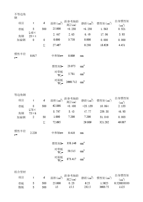
型材的剖面模数
项目四 钢质船舶规范法结构设计(4)组合型材的剖面设计

3)型材稳定性条件
型材腹板高而薄或面板过宽时, 型材腹板高而薄或面板过宽时,往往面板由于弯 曲压应力作用或腹板受过大的剪切作用而局部失 去稳定性, 去稳定性,因此型材的尺寸搭配应满足这种局部 稳定性的要求。 稳定性的要求。 要求腹板高厚比h/t< ,否则应设置加强筋, 要求腹板高厚比 <75,否则应设置加强筋, 长江实船h/t=50~60。 长江实船 。 经稳定性计算, 型材面板宽厚比 型材面板宽厚比b/δ< , 经稳定性计算,T型材面板宽厚比 <36,实 际可取b=( 际可取 (10~20)δ,折边型材减半。 ) ,折边型材减半。 h、b、t、δ的规定如图 所示。 的规定如图5-8所示 、 、 、 的规定如图 所示。
2.设计步骤 .
型材的剖面设计,就是确定型材剖面尺寸, 型材的剖面设计,就是确定型材剖面尺寸,使型材 满足强度、刚度及稳定性要求。 满足强度、刚度及稳定性要求。 现结合实例,说明组合型材剖面的设计步骤。 现结合实例,说明组合型材剖面的设计步骤。 某长江客货轮, 某长江客货轮,甲板纵桁所必须的剖面模数 W=404cm3,惯性矩 ,惯性矩I=7780cm4,甲板纵桁跨长 , l=7.7m,载荷的平均宽度b 2.35m, l=7.7m,载荷的平均宽度b = 2.35m,设计型材剖面 尺寸。 尺寸。
⑤确定面板尺寸 面板剖面积: 面板剖面积:
w h × t 404 30 × 0.6 f1= − = − = 13.5 − 4 = 9.5 cm 2 h k 30 4.5
⑥决定面板尺寸
δ = (1.2 ~ 2)t = 7.2 ~ 12 mm, 实取δ =8mm
950 b= = = 119 mm, 实取b = 120 mm δ 8 f1
1.首先确定腹板尺寸。 首先确定腹板尺寸。
剖面模数计算

56.00 50.00 50.00 72.00 50.00 50.00 84.00 50.00 50.00 50.00 91.00 91.00 50.00 50.00 50.00 50.00 50.00 50.00 60.00 60.00 50.00 50.00 50.00 50.00 50.00 50.00 50.00 50.00 50.00 50.00 50.00 50.00 50.00
zn
h
5.73 12.68680168
1.165
0.926
2.72
2.04
3.57
1.95
4.42
1.86
5.27
1.77
6.12
1.64
6.97
1.49
L400× 120×12
×23
W=1624.
0.85
12.69
4
662.22 89 cm3
L400×
120×12
×23
W=1624.
0.85
11.43
135.01 156.35 143.10 176.66 198.08 222.24 228.33 254.82 286.55 315.72 288.72 335.45 358.61
395.82 398.97 450.07 497.58 541.77 68.72 99.58 111.09 139.40 155.61 188.68 206.01 252.54 275.21 324.37 348.50 407.54 436.64 517.49 548.87
T型材计算
T型材带板面积
轧制型材计算
L63×40×4 L63×40×5 L63×40×6 L63×40×7 L75×50×5 L75×50×6 L75×50×8 L75×50×10 L90×56×5 L90×56×6 L90×56×7 L90×56×8 L100×63×6 L100×63×7 L100×63×8 L100×63×10 L100×80×6 L100×80×7 L100×80×8 L100×80×10 L110×70×6 L110×70×7 L110×70×8 L110×70×10 L125×80×7 L125×80×8
项目六--6.2.3型材剖面设计实例(精)

176N / m m2, M 77kN m,N 71kN, Y 235N / m m2,
任务2 优化设计船舶型材剖面
项目六
船舶型材剖面设计
1、计算 W1 和 f 0
W1
M
437.5cm2,f 0
N 9.5cm2 0.85
船舶技术设计
项目六
船舶型材剖面设计 6.2.3 型材剖面设计实例
学习内容: 某船用T型材的剖面优化设计 学习目标: 初步具有优化设计型材剖面的能力
任务2 优化设计船舶型材剖面
项目六
船舶型材剖面设计
例题:
已知条件:
88N / m m2,f 2 18cm2,t0 4m m,l 8m
式中: a1
W1 f ,a2 2 fh f
任务2 优化设计船舶型材剖面
项目六
船舶型材剖面设计
5、第二次近似决定m 因为:
2 f1 f 0.805 2 f2 f N 74.6n / m m2 0.85 f
0.424
则运用式(7-19),可得m=78.4
所以总稳定性可以得到保证。
任务2 优化设计船舶型材剖面
ቤተ መጻሕፍቲ ባይዱ
项目六
船舶型材剖面设计
拓展与思考
案例1:某船T型材主肋骨剖面的优化设计。
设规范对某船货舱主肋骨所要求的剖面模数 [W]=1200cm3 ,要求的剖面惯性矩 [I]=17640cm4 ,已知此货舱舷侧外板 厚度 t2 =18mm,肋距 s=0.78m,主肋骨跨距 l=4.5m,试设 计此主肋骨用T型材的剖面尺寸。
任务2 优化设计船舶型材剖面
第十六讲 型材剖面设计概要

因为K=4,所以 2 3 3 W0 0.75m t0 235.2cm (4)第一次近似计算型材剖面尺寸 2 < 及 < W0 W1 2W0 f 0 < mt0 hopt m t0 28cm 则
2 f m t0 11.2cm2
船体强度与结构设计
初取腹板尺寸为300×4,则
(7)确定面板尺寸
a2 (3a1 1) 0.25(6a1 1) f1 f 12.1cm2 3a2 1
由式(5.3.2)及(5.3.3)决定的n0在9~18之间。 由式(5.3.32)面板宽度为:
b1 2n0 f1 14.8 ~ 20.9cm
船体教研室吴春芳编 Email:qiuyuan_cat@
船体强度与结构设计
3)设计变量的类型
a.结构的剖面几何参数
b.结构的布局参数(如结构的型式,节点位 置,构件间距等) c.结构所用材料的参数 其中a是最常见也是最简单的一类结构优化设计
问题
明确一个标志:设计空间
船体教研室吴春芳编 Email:qiuyuan_cat@
船体教研室吴春芳编 Email:qiuyuan_cat@
船体强度与结构设计
3)可行域 满足所有约束条件的结构设计方案是可以被应 用的设计,称为可行域。 所有可行设计点的集合称为可行域。 构成可行域边界的约束曲面称为临界约束。
x1
0 = ) x h1(
h2(x )=0
0
可行域
0 = ) x ( h
f x min或 max
T
使目标函数 并受到约束
h j X 0
g k X 0
j 1,2,3, J k 1,2,3, K
剖面模数计算
r=
1.151
中和轴e= 0.098 cm
惯性矩I= 36.894 cm4
对带板 W1=
7.526
cm3
对面板 W2=
376.215
cm3
槽钢
项目
t
d
面积(cm2)
距参考轴距 离Z(cm)
静距(cm3)
惯性矩(cm4)
自身惯性矩 (cm4)
带板
10 1100 78.622 -0.500 -39.311
中和轴e= 0.410 cm
惯性矩I= 358.146 cm4
对带板 W1=
50.515
cm3
对面板 W2=
873.417
cm3
组合型材
项目
t
带板
5
腹板
5
d
面积(cm2)
距参考轴距 离Z(cm)
静距(cm3)
惯性矩(cm4)
自身惯性矩 (cm4)
500 25.000
0.25
6.25
1.5625 0.520833333
静距(cm3)
惯性矩(cm4)
自身惯性矩 (cm4)
500 62.898 -0.400 -25.159
10.064
2.133
8.797
5.43
47.77
259.38
46.95
50
1.000
7.200
7.200
51.840
0.003
∑ 72.695
29.809
321.282
49.087
惯性半径
r=
2.220
惯性矩I= 621.146 cm4
对带板 W1=
64.359
型材的剖面模数

1380 1400 1450
1500
1550 1600
1650
1700 1750 1800 1850 1900
1950
2000 2050
2100
2150 2200 2250 2300 2350 2400 2450
具有附连翼板的剖面,(mm)
- 370×14 - 370×15
- 360×28 - 380×26 - 400×24
- 280×12
580
- 280×22
肘板尺寸
折
无折边
有折边 边
55
mm - 280×9.5 - 280×8.0
- 290×9.5 - 290×8.0
折 边 60
- 310×10.5 - 310×8.5
mm
- 315×10.5 - 315×8.5 - 320×10.5 - 320×8.5
- 330×11.0 - 330×9.0
- 200×17
240 - 150×100×12
- 220×15
250 - 180×90×10 -200×11.5 - 200×18
260 - 160×80×14
- 220×16 - 240×14
肘板尺寸
无折边
有折边
- 180×7.0 - 180×6.5
折 边 - 190×7.0 - 190×6.5
- 370×13
肘板尺寸
无折边
有折边
- 370×12.0 -370×9.5
折 边 - 380×12.0 -380×10.0
70 mm
- 390×12.5 -390×10.0
折 - 400×13.0 - 400×10.5 边
型材剖面模数计算

型材剖面模数计算要计算型材剖面的模数,首先需要了解型材的截面形状。
常见的型材包括角钢、圆钢、槽钢、工字钢等,每种型材的截面形状都有所不同。
这些型材的截面形状可以通过几何测量或CAD软件进行测量和绘制。
一般来说,计算型材剖面模数可以通过以下步骤进行:1.测量型材的截面尺寸:使用尺子或卡尺等工具测量型材的截面尺寸,并记录下来。
比如,对于角钢的剖面,可以测量上下边缘的高度和左右边缘的宽度。
2.计算型材的截面面积:根据测量得到的尺寸,可以计算出型材的截面面积。
对于角钢的剖面,可以将上下边缘的高度乘以左右边缘的宽度,得到截面的面积。
3.计算型材的惯性矩:惯性矩是衡量型材在受力时抵抗形变的能力。
计算型材的惯性矩需要使用型材的截面尺寸来进行计算。
惯性矩的计算公式根据型材的截面形状和坐标系的选择有所不同。
对于简单的截面形状,比如矩形、圆形等,可以使用经典的惯性矩计算公式进行计算。
对于复杂的截面形状,可以使用CAD软件进行建模,并通过软件提供的计算工具进行计算。
4.计算型材的模数:型材的模数可以通过将型材的惯性矩除以型材的最远离中性轴的距离得到。
模数的计算结果就是型材在剖面上的抗弯刚度。
模数的大小可以反映型材的强度和刚度。
模数越大,说明型材的强度和刚度越大,能够承受更大的外力而不产生较大的形变。
在实际工程应用中,可以根据型材的截面尺寸和模数来选择合适的型材进行设计。
对于需要承受较大外力的结构,应选择截面积大、模数大的型材,以提高结构的强度和刚度。
对于受力相对较小的部位,可以选择截面积小、模数小的型材,以减小结构的重量和成本。
剖面模数计算方法

Allowable stress to ABS MODU 2001, part 3, charpter 2, section 1, item 3.3F=Fy/F.S., whereFy = 235 N/mm2 , or 34 ksiF.S. = 1.67 for axial or bending stress2.50 for shear stressHence, F = 140.7 N/mm2 , or 20.4 ksi for axial or bending stress94.0 N/mm2 , or 13.6 ksi for shear stress1. Bulkhead1.1 Wind pressure p = f V k2.c h.c s N/m2wheref = 0.611Vk = 100 knots = 51.44 m/sc s = 1.0c h = 1.1hence p = 1778.4 N/m2or 37.13 lbf/ft21.2 Bulkhead platingPlate panel maximum size (mm)4070 by 690Plate thickness, t (mm)8Bulkhead load to wind pressure p = 1778.4 N/m2or 37.13 lbf/ft2Stress due to lateral perpendicular load:σ = kpb2/t2 wherek = 0.741 for panel size ratio of 5.9 (4070/690)p =37.13lbf/ft2, or0.26 lbf/in2b =690 mmt =8mmHenceσ =1421 lbf/in2, or 1.42ksi OK3Shear stress at support,τ = RF max/A web = 4.49N/mm2, or0.7ksi OK2. Bottom2.1. bottom platingPlate panel maximum size (mm)2650 by 830Plate thickness, t (mm)8Deck load to MODU 2001, w920 kgf/m2, or 188 lbf/ft2Stress due to lateral perpendicular load:σ = kwb2/t2 wherek = 0.718 for panel size ratio of 3.19 (2650/830)w =188lbf/ft2, or 1.31 lbf/in2b =830mmt =8mmHenceσ =10090 lbf/in2, or10.1ksi OK33. APV' lower Supporting StructureAs per contract specification 2.22G, foundations for equipment shall be designed for combined staticand dynamic load of 1.5g vertical and 0.5g horizontal for roll and pitch.According to HYDRALIFT Drawing: T2820-D1157-G0040 APV's arrangement,per WORKING APV' average weight: 2750kg,add 10% variables: 3025kg is to be used in following calculation.3.1 check supporting plate panelThe supporting plate panel, which is supported at four sides, is considered conservatively as plate beam supported at two longer edges.Plate panel concentrated load maximum size (mm)1420 by 760Plate thickness, t (mm) =25.5Deck load to MODU 2001, w =920kgf/m2, or 188 lbf/ft2Max moment due to deck load q: M q =qL/8 =925N.mwhere L =0.76mMax reaction force due to deck loa R q=qL/2=4870NLoad Case 1 (LC1): Heave at 1.5gForce due to static and dynamic load:P = ma,wherem=3025kga=14.7m/s2 (1.5g)P=44467.5NHence,Q=2P = 88935NM1max=Ql1l2/L=16605N.mwhere L=0.76ml1=0.33ml2=0.43mR1max=Ql2/L=50318NForce due to pitch:P=ma,wherem=3025kga= 4.9m/s2 (0.5g)P pitch=14822.5NHence,Q2=2.755*P/5.76 = 7090NThe force acts on plate as a longitudinal tension, as illustrated in sketchLC3: Roll at 0.5g to starboardForce due to roll:P=ma,wherem=3025kga= 4.9m/s2 (0.5g)P=14822.5NHence,Q2=2.755*P/5.76 = 7090NThe force acts on plate as a transverse tension, as illustrated in sketchLC4: Heave at 1.5g, pitch at 0.5g to forward and roll at 0.5g to starboard (LC1+LC2+LC3)moment:BM max=M1max + Mq =17530N.mshear:RF max=R1max + Rq =55188Nlongitudinal tension:TF x =14179Ntransverse tension:TF y =14179Nplate beam modulus:SM=bt2/6 =154cm3where b =142cmt = 2.55cmplate beam area:A1 =bt =362cm2A2 =at =194cm2where a =76cmBending stress,σ = BM max/SM =113.91N/mm2, or16.5ksi OK Shear stress,τ = RF max/A1 = 1.52N/mm2, or0.2ksi OK Longitudinal tension stress:σx = TF x/A2 =0.73N/mm2, or0.1ksi OK Transverse tension stress:σy = TF y/A1 =0.39N/mm2, or0.1ksi OK3.2 Check supporting structurewhere L= 1.42mBM max = (q1+q2)L2/8 =1774kgf.mRFmax = (q1+q2)L/2 = 4997kgf3Bending stress ,σ = BM max/SM = 6.21N/mm2, or0.9ksi OK Shear stress ,τ = RF max/A1 = 6.81N/mm2, or 1.0ksi OKb. Beam A2-B2Similar to beam A1-B1, check beam A2-B2 stress is OK.R B2 =4964kgfc. Beam A3-B3Similar to beam A1-B1, check beam A3-B3 stress is OK.R B3 =2697kgfd. Beam A4-B4Similar to beam A1-B1, check beam A4-B4 stress is OK.R B4 =2482kgfe. Beam A5-B5Similar to beam A1-B1, check beam A5-B5 stress is OK.R B5 =4964kgff. Beam A6-B6Similar to beam A1-B1, check beam A6-B6 stress is OK.R B6 =4964kgfg. Beam A7-B7Similar to beam A1-B1, check beam A7-B7 stress is OK.R B7 =4964kgfh. Beam A8-B8Similar to beam A1-B1, check beam A8-B8 stress is OK.R B8 =4964kgfi. Beam A9-B9Similar to beam A1-B1, check beam A4-B4 stress is OK.R B9 =2482kgfj. Beam C1-D1Similar to beam A1-B1, check beam C1-D1 stress is OK.R C1 =4989kgfR D1 =4989kgfk. Beam C2-D2Similar to beam A1-B1, check beam C2-D2 stress is OK.R C2 =4957kgfR D2 =4957kgfl. Beam C3-D3Similar to beam A1-B1, check beam C2-D2 stress is OK.R C3 =2690kgfR D3 =2690kgf3.2.2 Check transverse girdersMax moment due to force R B1: M B1 = 0.76*1.985*R B1/2.745 =2746kgf.mMax moment due to force R B2: M B2 = 1.42*1.325*R B2/2.745 =3402kgf.mMax moment due to force R B3: M B3 = 2.08*0.665*R B3/2.745 =1359kgf.m Combined moment: BM max =6163kgf.mReaction force: R E1 = 1.985*R B1/2.745 + 1.325*R B2/2.745 + 0.665*R B3/2.745 =6663kgf Reaction force: R F1a = 0.76*R B1/2.745 + 1.42*R B2/2.745 + 2.08*R B3/2.745 =5995kgf hence,RF max =6663kgfBending stress ,σ = BM max/SM =24.00N/mm2, or 3.5ksi OK Shear stress ,τ = RF max/A WEB =8.17N/mm2, or 1.2ksi OKn. Beam E2-F2Similar to beam E1-E1, check beam E2-F2 stress is OK.Reaction force: R F2 =5984kgfDistributed load along the beam length due to bulkhead weight, q = 660kgf/mMax moment due to load q: M q =qL2/8 =622kgf.mMax moment due to force R D1: M D1 = 0.76*1.985*R D1/2.745 =2742kgf.mMax moment due to force R D2: M D2 = 1.42*1.325*R D2/2.745 =3398kgf.mMax moment due to force R D3: M D3 = 2.08*0.665*R D3/2.745 =1355kgf.mCombined moment: BM max =6774kgf.mReaction force: R E3 =7558kgfReaction force: R F3a =6890kgfhence,RF max =7558kgfBending stress ,σ = BM max/SM =26.38N/mm2, or 3.8ksi OK Shear stress ,τ = RF max/A WEB =9.27N/mm2, or 1.3ksi OKDeck load to MODU 2001, w = 920kgf/m2 or 188 lbf/ft2Distributed load along the beam length, q = 0.165*w =151.8kgf/mMax moment due to load q: M q =q*1.4452*(1+1.3/2.745)2/8 =86kgf.mMax moment due to force R B4: M B4 = 1.445*1.3*R B4/2.745 =1699kgf.mMax moment due to force R B5: M B5 = 2.105*0.64*R B5/2.745 =3402kgf.mCombined moment: BM max =4259kgf.mReaction force: R F1b =2424kgfReaction force: R =5146kgfthk(cm)width(cm)sectionarea(cm2)ctr.dist. toplt top(cm)d(cm)I0 (cm4)mom. ofinert.(cm4)SM(cm3)top flg 2.5516.542.075 1.27522.844135.0web1808042.5542666.748997.3btm flg0.816.513.282.950.732077.6 Combined135.27533.7125210.02520 Bending stress ,σ = BM max/SM =16.58N/mm2, or 2.4ksi OK Shear stress ,τ = RF max/A WEB = 6.31N/mm2, or0.9ksi OKDeck load to MODU 2001, w = 920kgf/m2 or 188 lbf/ft2Distributed load along the beam length, q1 = 0.165*w =151.8kgf/mDistributed load along the beam length due to bulkhead weight, q2 = 660kgf/m BM max = (q1+q2)L2/8 =765kgf.mRFmax = (q1+q2)L/2 = 1114kgfHence,R =1114kgfBending stress ,σ = BM max/SM = 2.98N/mm2, or0.4ksi OK Shear stress ,τ = RF max/A WEB = 1.37N/mm2, or0.2ksi OKr. Beam E5-F5Similar to beam F3-E5, check beam E5-F5 stress is OK.Reaction force: R E5b =1185kgfR F5 =1185kgfDeck load to MODU 2001, w = 920kgf/m2 or 188 lbf/ft2Distributed load along the beam length, q = 0.165*w =151.8kgf/mMax moment due to load q: M q =q*0.832*(1+2.66/3.49)2/8 =41kgf.mMax moment due to force R B6: M B6 = 0.68*2.81*R B6/3.49 =2718kgf.mMax moment due to force R B7: M B7 = 1.34*2.15*R B7/3.49 =4098kgf.mMax moment due to force R B8: M B8 = 2.0*1.49*R B8/3.49 =4239kgf.mMax moment due to force R B9: M B9 = 2.66*0.83*R B9/3.49 =1570kgf.mCombined moment: BM max =9829kgf.mReaction force: R E4b =9779kgfBending stress ,σ = BM max/SM =38.27N/mm2, or 5.6ksi OK Shear stress ,τ = RF max/A WEB =11.99N/mm2, or 1.7ksi OK3.2.3 Check longitudinal girdersDeck load to MODU 2001, w = 920kgf/m2 or 188 lbf/ft2Distributed load along the beam length, q = 0.3*w =276kgf/mMax moment due to load q: M q =q*3.5882/2 =1777kgf.mMax moment due to force R F1a +R F1b: M F1 = 0.938*(R F1a+R F1b) =7897kgf.mMax moment due to force R F2: M F2 = 2.193*R F2 =13123kgf.mMax moment due to force R F3a +R F3b: M F1 = 3.588*(R F3a+R F3b) =29041kgf.mCombined moment: BM max =51838kgf.mReaction force: R G1 = q*3.588 + RF1a + RF1b + RF2 + RF3a + RF3b=23397kgfBending stress ,σ = BM max/SM =167.46N/mm2, or24.3ksi OK Shear stress , 1.2τ = RF max/A WEB =65.58N/mm2, or9.5ksi OKDeck load to MODU 2001, w = 920kgf/m2 or 188 lbf/ft2Distributed load along the beam length, q1 = 0.3*w =276kgf/mLoad as Heave at 1.5gForce due to static and dynamic load:P = ma,wherem=3025kga=14.7m/s2 (1.5g)P=44468NHence,q2=2P/L = 6384kgf/mwhere L= 1.42mMax moment due to load q1: M q1 =q1*4.072/2 =2286kgf.mMax moment due to load q2: M q2 =q2*1.422/2 =6437kgf.mMax moment due to force R E4a +R E4b: M E4 = 1.42*(R E4a+R E4b) =21194kgf.mMax moment due to force R E5a +R E5b: M E4 = 4.07*(R E5a+R E5b) =9357kgf.mCombined moment: BM max =39273kgf.mReaction force: R G2 = q1*4.07 +q2*1.42 + R E4a + R E4b + R E5a + R E5b=27413kgf hence,RF =27413kgfBending stress ,σ = BM max/SM =65.74N/mm2, or9.5ksi OK Shear stress ,τ = RF max/A WEB =26.89N/mm2, or 3.9ksi OKv. Beam G3-F5Deck load to MODU 2001, w = 920kgf/m or 188 lbf/ft2Distributed load along the beam length, q1 = 0.165*w =151.8kgf/mDistributed load along the beam length due to bulkhead weight, q2 = 660kgf/m Max moment due to load q1: M q1 =q1*4.072/2 =1257kgf.mMax moment due to load q2: M q2 =q2*4.072/2 =5466kgf.mMax moment due to force R F4: M F4 = 1.42*R F4 =10964kgf.mMax moment due to force R F5: M F5 = 4.07*R F5 =4823kgf.mCombined moment: BM max =22510kgf.mBending stress ,σ = BM max/SM =62.18N/mm2, or9.0ksi OK Shear stress ,τ = RF max/A WEB =11.26N/mm2, or 1.6ksi OK4. APV' Upper Supporting Structure3.1 :P pitch =14822.5NQ1pitch =7733N Load due to a APV's Roll at 0.5g to starboard has calculated as 3.1 :P roll =14822.5NQ1roll =7733N 4.1 Check APV' end box mounting structure on forward transverse bulkhead4.1.1 Check stiffener' flange subjected to tensionAs per "Yield Line Analysis of Bolted Hanging Connections", AISC, Engineering Journal, Vol.14, No.3 1977, For hanger rods, the allowable working load is the smaller of following :P1 = F y t b2(2r)1/2(1+a/b)/LFP2 = F y t b2[r(1+a/b)]1/2/LFwhere F y=235N/mm2t b=13mmr= (F y-F b)/F y =0.401F b=140.7N/mm2a=50mmb=35.5mmLF = 1.7P1 =50388NP2 =22959Nhence,the allowable total force carried by flange[ P ]=22959Nmaximal load forced on stiffener L100x75x13 is P max = 1.5Q1roll = 11600 N < [ P ]OK!4.1.2 Check stiffener subjected to compressionR max =8522N9thk(cm)plt width/sect dep(cm)sectionarea(cm2)ctr.dist. toplt top(cm)d(cm)I0 (cm4)mom. ofinert.(cm4)SM(cm3)att plt0.85644.80.4 2.493.9section-7.515.46 5.9794.6359.7Combined60.26 1.8453.6704.3in3 Bending stress ,σ = BM max/SM =23.83N/mm2, or 3.5ksi OKR max=R F =8738Nthk(cm)plt width/sect dep(cm)sectionarea(cm2)ctr.dist. toplt top(cm)d(cm)I0 (cm4)mom. ofinert.(cm4)SM(cm3)att plt 1.2519.2240.625 3.1196.0section-7.521.06 6.6994.6314.4Combined45.06 3.5510.3965.9in3Bending stress ,σ = BM max/SM =22.61N/mm2, or 3.3ksi OK Shear stress ,τ = RF max/A1 = 4.15N/mm2, or0.6ksi OKC. Check beam L-MR max =11934Nthk(cm)width(cm)sectionarea(cm2)ctr.dist. toplt top(cm)d(cm)I0 (cm4)mom. ofinert.(cm4)SM(cm3)top flg00000.00.0web0.9 2.5 2.25 1.25 1.2 4.8btm flg0.97.5 6.75 2.950.5 1.7Combined9 2.5 6.530.2in3 Bending stress ,σ = BM max/SM =4145.20N/mm2, or601.6ksi OK Shear stress ,τ = RF max/A1 =53.04N/mm2, or7.7ksi OK4.2 Check APV' end box mounting structure on inboard longitudinal bulkheadAs per "Yield Line Analysis of Bolted Hanging Connections", AISC, Engineering Journal, Vol.14, No.3, 1977, For hanger rods, the allowable working load is the smaller of following :P1 = F y t b2(2r)1/2(1+a/b)/LFP2 = F y t b2[r(1+a/b)]1/2/LFwhere F y=235N/mm2t b=19mmr= (F y-F b)/F y =0.401F b=140.7N/mm2a=50mmb=35.5mmLF = 1.7hence,P1 =107634NP2 =49042Nhence,the allowable total force carried by flange[ P ]=49042Nmaximal concentrated load forced on girder T 811x12.5w P max = 3Q2roll = 23199 N < [ P ]OK!4.2.2 Check longitudinal girder' web stability under compression when roll to starboardAs per "Manual of STEEL CONSTRUCTION Allowable Stress Design", AISC,Slenderness ratio Kl/r =450> 200where K =2l =811mmr = 3.61mmAnd C c =(2*3.142E/F y)1/2 =130where E =200000MpaF y =235N/mm2here,Kl/r >C chence,the allowable stress F a = 12*3.142E/(23*(Kl/r)2 = 5.08N/mm2Compression total load forced on Girder' web section Q =12*Q2roll92796N web section area A=19625mm2RF max =92796Nthk(cm)width(cm)sectionarea(cm2)ctr.dist. toplt top(cm)d(cm)I0 (cm4)mom. ofinert.(cm4)SM(cm3)top flg 2.5547.3120.615 1.27565.474578.2web 1.2581.1101.37543.155563.784757.5btm flg 1.911.521.8584.6 6.674705.9Combined243.8426.1234041.73939240.4in3 Bending stress ,σ = BM max/SM =17.91N/mm2, or 2.6ksi OK Shear stress ,τ = RF max/A web =9.15N/mm2, or 1.3ksi OK4.3 Check supporting APV' end box mounting structure on TF-12 transverse bulkheadBending stress ,σ = BM max/SM =72.79N/mm2, or10.6ksi OK Shear stress ,τ = RF max/A web =17.26N/mm2, or 2.5ksi OKthk(cm)width(cm)sectionarea(cm2)ctr.dist. toplt top(cm)d(cm)I0 (cm4)mom. ofinert.(cm4)SM(cm3)top flg 1.310130.65 1.8871.8web 1.3 6.28.06 4.425.8184.0btm flg 1.957.5109.258.4532.948.7web 1.2581013.453.3262.1top flg 1.25121518.025 2.01270.1Combined155.318.8302636.726916.4in3Bending stress ,σ = BM max/SM =74.44N/mm2, or10.8ksi OK Shear stress ,τ = RF max/A web =17.26N/mm2, or 2.5ksi OK。