第一章模拟与Automod模拟软体
Autoform - 教程

薄板冲压成型仿真软件— Autoform功用解析Jason Hu YunBin•前言目前,在薄板冲压成型仿真领域,Autoform软件的市场占有率为全球第一。
全球 90% 以上的汽车制造商在使用 AutoForm。
全球前 20 家最大的汽车制造商 100% 在使用AutoForm。
全球超过 100 家模具制造商与薄板冲压件制造商均在使用AutoForm。
在德国, AutoForm 市场占有率为 90% 以上。
在全球, AutoForm 市场占有率为 80% 以上。
在国内,AutoForm目前拥有众多的行业用户,如上海大众汽车有限公司、一汽模具制造有限公司、东风汽车模具有限公司、成飞集成科技股份有限公司及天津汽车模具有限公司等。
Autoform自面世至今不过十来年,其进入中国市场也不过短短三、四年时间,却获得了业界的一片喝彩与赞誉,缘由何在?Autoform是一款CAE仿真软件,我们知道,CAE是计算机辅助工程(Computer Aided Engineer)的简称。
对工程应用实际的辅助功能全面,操作简便,提高工程方案的可靠性,缩短方案制定周期等方面都具有强大的辅助功能,能实实在在的提高工作效率,使应用者对自己的工作方案在实施前就做到心中有底,有效减少实际工作中的不确定性,这些无疑都是评价一款CAE软件是否优秀的重要标准。
Autoform的出现,冲击和改变了许多传统的CAE仿真理念。
其界面简单,操作简便,无需用户具备有限元知识,消除了一般工程技术人员对CAE 仿真分析的神秘感,促进了CAE分析的工业应用。
由于在众多有限元技术上的突破,使得AutoForm在计算速度上具有很大的优势,也推翻了动态显式算法计算效率优于静态隐式算法的传统观念。
其在接触处理算法上的突破,使得应用者从此无需再将大量宝贵的时间耗费在单元网格处理之中。
其功能强大的模面设计模块,使得应用者无需再将大量时间耗费在繁冗的CAD数据处理之中,而将精力专注于方案本身。
几种常用的仿真工具

几种常用的仿真工具 em-plante automod witness flexsim几种常用的仿真工具1)eM-PlanteeM-Plant是Tecnomatix公司一个生产过程仿真软件系统,可以对各种规模的工厂和生产线,包括大规模的跨国企业,建模、仿真和优化生产系统,分析和优化生产布局、资源利用率、产能和效率、物流和供需链,以便于承接不同大小的订单与混和产品的生产。
它使用面向对象的技术和可以自定义的目标库来创建具有良好结构的层次化仿真模型,这种模型包括供应链、生产资源、控制策略、生产过程、商务过程。
用户通过扩展的分析工具、统计数据和图表来评估不同的解决方案并在生产计划的早期阶段做出迅速而可靠的决策。
主要特点:可裁剪工厂模块;与CAD、CAPE、ERP和数据库系统实时通讯和集成;客户化用户接口;使用遗传算法(genetic algorithms)对系统参数进行自动优化;适合于专用加工应用如白车身车间、喷漆车间、工作车间的应用对象库;在面向对象的用户环境中建立、更新和维护模型;可重复使用的工程模型。
2)AutomodAutomod是目前市面上比较成熟的三维物流仿真工具。
主要包括了三大模块:AutoMod、AutoStat和AutoView。
AutoMod模块提供给用户一系列的物流系统模块来仿真现实世界中的物流自动化系统。
主要包括输送机模块(辊道、链式),自动化存取系统(立体仓库、堆垛机),基于路径的移动设备(AGV等),起重机模块等。
AutoStat模块为仿真项目提供增强的统计分析工具,由用户定义测量和实验的标准,自动在AutoMod的模型上执行统计分析。
主要特点:基于发展策略运算法则的最优化分析,用户为得到更好的模型来定义输出审核,多CPU并行计算等;AutoView可以允许用户通过AutoMod模型定义场景和摄像机的移动,产生高质量的A VI格式的动画;用户可以缩放或者平移视图,或使摄像机跟踪一个物体的移动,如叉车或托盘的运动;AutoView可以提供动态的场景描述和灵活的显示方式。
automod简体中文教程 3_Conve

12
Applied Materials Confidential
系统定义的属性
load type
─ 保存实体类型名称的字符串属性
priority
─ 保存优先级的整型属性,缺省值为0
current process
─ 单元类型属性,保存load所属的当前进程
absolute clock(ac)
– 记录系统从仿真开始的时刻经过的时间
11
Applied Materials Confidential
语法 if … then … else
if 关系式 then 命令语句 else 命令语句 if 关系式 then 命令语句 else if 关系式 then 命令语句 else 命令语句 复合语句 if 关系式 then begin 命令语句1 … 命令语句n end 命令语句超过2 命令语句超过2个的时候要用到 复合语句
4
Applied Materials Confidential
Conveyor 画图工具条
跟我做:新建模型,新建conveyor系统:conv1; 进入conveyor编辑窗口,出现画图工具条
– – – – – – Single line: 单一直线 Single arc:单一圆弧 Continuous:连续的 Connected:连接的 Fillet:链接,剪切 Station:位置点
16 Applied Materials Confidential
8
Applied Materials Confidential
语法: 语法:move into
move into
– 作用:将实体移动到新的域( territory)中; – 语法: move into 下个域的名称 ; – 域的命名规则: systemname.stationname
AutoModChapter07Slides

Determining when to use variables versus load attributes
• Use variables to track information that applies to
the entire model
• Use load attributes to track information that is
For example “PartA,” “the 5 loads,” “135hd98,” and “15” are all string valueபைடு நூலகம்.
Getting Started with AutoMod, 2nd ed.
Chapter 7
Slide 6 of 36
Setting variable and load attribute values
QueuePtr
A pointer to a queue in the model.
ResourcePtr
A pointer to a resource in the model.
LoadTypePtr A pointer to a load type in the model.
begin P_init arriving procedure set V_intval to 5 set V_intval to 6 set A_realval to 5.3 set V_timeval to 5 set A_stringval to “Simulation” set V_queueptr to Q_enter set A_ltptr to L_part
• “set V_intval = 5” is the same as “set V_intval to 5”
专业版与学生版(AUTOMOD automod)
2-1-11 AutoMod 学生版限制在 AutoMod 的学生版中建构模式会有实体上的限制,一个模式中实体不能超过200 个,而11.0 版以前的版本限制为100 个,这些实体指的就是如人员、设备、储存区等等。
此外,移动系统部分,只有Conveyor 系统及Path Mover 系统可供使用。
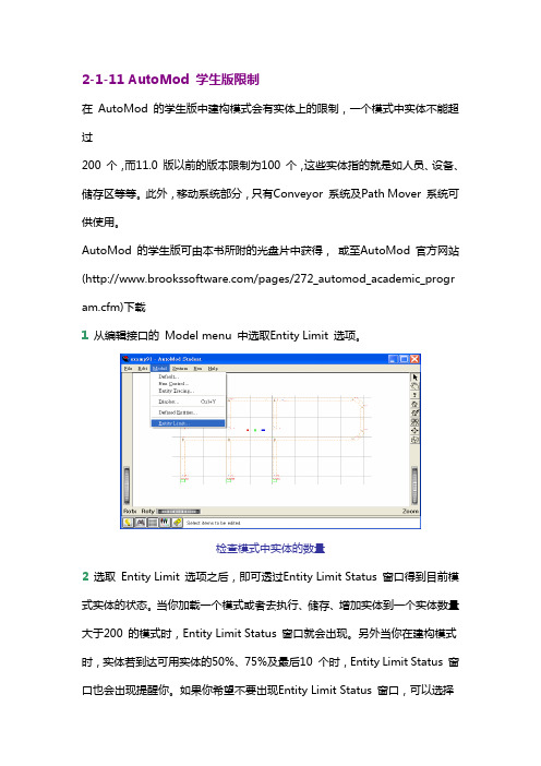
AutoMod 的学生版可由本书所附的光盘片中获得,或至AutoMod 官方网站(/pages/272_automod_academic_program.cfm)下载1 从编辑接口的 Model menu 中选取Entity Limit 选项。
检查模式中实体的数量2 选取 Entity Limit 选项之后,即可透过Entity Limit Status 窗口得到目前模式实体的状态。
当你加载一个模式或者去执行、储存、增加实体到一个实体数量大于200 的模式时,Entity Limit Status 窗口就会出现。
另外当你在建构模式时,实体若到达可用实体的50%、75%及最后10 个时,Entity Limit Status 窗口也会出现提醒你。
如果你希望不要出现Entity Limit Status 窗口,可以选择Disable Warnings 的选项来关闭它。
模式中实体限制状态除此之外,这些实体会根据其本身之特性,被分类于不同的系统,如输送带系统、搬运系统等等。
因此为了得到更详细的实体数据,可以选择Show Entity Allocation 的选项来得到相关信息。
实体分类2-1-12 AutoMod 学生版与专业版之切换在某些情况下,我们会有学生版与专业版之间切换的需求,譬如:原先已安装了学生版,但因为已购买专业版而想改成专业版因教学需要,专业版数目不足而需改为学生版要将网络Server 专业版改为单机专业版要将单机专业版改为网络Server专业版我们可以不用重新安装而透过底下所介绍的小技巧来达成。
【机械类文献翻译】AutoMod 软件的柔性制系统与仿真

英文原文Intelligent Information Management, 2011, 3, 186-189doi:10.4236/iim.2011.35022 Published Online September 2011(/journal/iim) Simulation of a Flexible Manufacturing System with AutoMod SoftwareZixia Chen1, Changbing Jiang21Yibin Vocational and TechnicalCollege, Yibin, China 2ZhejiangGongshang University, Hangzhou,China E-mail:czx@,jcb@Received June 2, 2011; revised July 4, 2011; accepted July 15, 2011 AbstractA flexible manufacturing system (FMS) is a highly automated, complex system. Simulation is a well -proven method to design or analyze an FMS. Deployment of a radio frequency identification (RFID) system in FMS produces large volumes of RFID data streams, which provide valuable information to improve the operation of FMS. Different frameworks are presented in this paper regarding the use of RFID data streams in an FMS simulation. Simulations are performed with AutoMod software. Related technical details are also presented. The pape r’s structure is complied as the following steps: step 1, the introduction of AMHS, FMS and AutoMod; step 2, FMS simulation using AutoMod software; step 3, simulation frameworks driven by RFID data streams; step 4, conclusion.Keywords:FMS, RFID, Data Stream, Simulation, AutoMod Software1. Introduction1.1. AMHS and FMSAn automated materials handling system (AMHS) stores, retrieves and moves materials through processes to change their form and packaging. It relies primarily on automated devices to handle these materials. AMHS, such as the Automated Storage and Retrieval System (AS/RS) used in thelogistics sector or other automated material handling systems utilized in factories play an important role in this aggressively competitive environ-ment [1,2]. Therefore, improvements to AMHS are of great value.The flexible manufacturing system (FMS) plays a more and more important role in AMHS. Figure 1de-monstrates a flexible manufacturing system that pro-cesses metal parts. The storage/retrieval machine (S/RM) retrieves pallets of raw parts from the storage racks and places them on conveyors at the end of each aisle. An operator then removes a part from its pallet and fastens it to a fixture on an adjacent conveyor. The conveyor transports the fixtures to a pickup point, where they are loaded onto an automated guided vehicle (AGV).Six computer numeric control (CNC) machines pro-cess parts in the system. A head changer is also available for drilling the parts. The AGVs transport the fixtures to the required CNCs, or head stations. When all processing of a part has been completed, an AGV returns the part with its fixture to the conveyor near the storage racks. An operator removes the completed part from the fixture and returns it to a pallet for storage on the racks. The empty fixture then circulates on the conveyor to receive a new raw part.This FMS is a typical discrete event system. While it is difficult to evaluate its efficiency with traditional methods because of random factors and computing com-plexity, simulation is a well-proven way to design and analyze FMS.Figure 1. An example of a flexible manufacturing system1.2. RFID Data Collection in FMSRFID is a powerful data collection method which can be used in product control and material handling or other material flow processes [3]. With deployment of RFID systems in FMS, operation control is strengthened with the better visibility of the process. In FMS, pallets, totes or other loads which are flowing through the FMS are tagged with RFID tags. RFID readers read the tags which store the processing information at a pre-assigned loca-tion. Sensors (RFID readers) collect the information of material which flows through the processes, and then sends this information into the database. Under certain rules, meaningful events trickle, this could be used todrive Supply Chain Management (SCM) [4], Enterprise Resource Planning (ERP) or Manufacturing Execution System (MES) information systems. Service-oriented architecture (SOA) and event-driven architecture (EDA) are dominant in this field [5,6]. The RFID readers can provide real-time material flow information like probes in the object system. The information includes item in-formation, location, processing time and arrival time with high accuracy. It can be stored in a data stream, into a database or a data warehouse.For FMS as in Figure 1, RFID readers can be set up at an AS/RS I/O station, a CNC work station and at AGV pickup points. Tags are tagged on pallets and fixtures. When pallets or fixtures flow through the system, readers read the tags and create data records as in Table 1. These records are then processed by RFID middleware. Finally, large volume records will be stored as data streams in an RFID data warehouse [7]. Thus, RFID data becomes the bridge that connects the physical world to the virtual world.1.3. Challenges in FMS SimulationThe environment in which FMS operates is stochastic in nature. So when designing and analyzing FMS, this na-ture must been taken into consideration. Simulation is a powerful tool to tackle a stochastic situation [8]. There are commercial software packages which can be used to Table 1. RFID tag records.Tag ID LoadItemTimeReader Type(hh:mm:ss:ms)IDEE07000001A34621pallet raw114:01:45:351EE07000001A34622pallet raw214:01:45:552EF01000001A34621fixture P114:05:05:553EF01000001A34622fixture P214:05:06:154EF01000001A34623fixture P314:05:07:055simulate FMS. But simulation is still a job which needs talented people especially when theobjective system is complex. Generally, commercial simulation software packages may alleviate these efforts dramatically, be-cause we can use them to model FMS with the visual entities and components in their Graphical User Inter-faces (GUIs), but for invisible data or I/O data, there is not an efficient way to model them. Under many circum-stances, a pseudo-random number generator is the only way to drive an FMS simulation.Random numbers are used in simulations to introduce the variability of the real world into a model. Product inter-arrival times, processing times, time until machine failures, and repair times are examples of events with a duration that varies throughout the operation of a real system. When building a model, decisions must be made how to represent randomly occurring events in the simu-lation. A popular technique is to attempt to fit estimated or historic real-world data to a distribution. But for FMS, high throughput means a high volume of data. Data analysis is very difficult. On the other hand, so much in-process data is stored in MES or other enterprise in-formation systems, particularly with the deployment of an RFID system. This formal data can be utilized in an FMS simulation.In the following part of this article, we will discuss FMS simulation using commercial software.A simula-tion framework using RFID data stream will also be pre-sented.2. FMS Simulation Using AutoMod SoftwareAutoMod suite is world-leading industrial simulation software, which is provided by Applied Materials, an American company. It has many successful applications in various sectors, such as automobile, semiconductor, aerospace and defense, paper, logistics etc. Many of the top 500 companies in the world have used AutoMod to simulate their production logistics in order to improve the operation and efficiency of departments, reduce in-ventory and cash flow [9,10].AutoMod is actually a combination of two programs: a build package and a runtime package. The build package is for physical and logical model definition. After the user has defined the physical and logical components of the model, it is compiled into an executable program, where the simulation and animation run concurrently. The executable model runs very fast and is fully interac-tive; it can be stopped at any instant in simulated time to view statistics and model status. The latest version of AutoMod provides database I/O functions and a model communications module which supports OPC (OLE for Process Control) or sockets communication.The visual components of FMS can be easily modeled with professional AutoMod modules, such as AS/RS, process, conveyor and path-mover subsystem. Without real world data, an FMS model is usually driven by pseudo-random streams or simple sample data which simplify the inputor in-process data. Data acquisition codes are embedded in the AutoMod logic files.3.Simulation Frameworks Driven by RFID Data StreamsThere are applications in different types of DEVS (Dis-crete Event Systems) simulations using RFID data. For example, RFID data was used to simulate and analyze hospital operations and resource utilization. From above we know that RFID data can drive the virtual AutoMod model in place of the pseudo-random streams or simple samples. Knowing how to use the RFID data streams collected in the FMS operation period is the problem we need to address. According to different RFID data sources, there are two ways to use RFID data streams in an FMS simulation. An individual framework will be presented under each mode in the following section. Technical details will also be mentioned.In both these modes, the simulation software concen-trates on the operational characters of RFID tags and tagged object name, such as arrival time, arrival location. Other information in the tags is not sent to the software. The transferred information must be formal and can be parsed into meaningful events which can be understood by the software. Transparent standards and protocols must be complied with before the simulation.3.1. Offline Mode (Historical RFID Data)In offline mode, a simulation model is driven by histori-cal RFID data streams stored in a database. In this mode, processed RFID data has been stored in a database. When an AutoMod model of FMS runs, it reads Auto-Mod database I/O functions (like Open Database Con-nectivity function) and parses the RFID data streams into certain events which are meaningful to AutoMod. Figure2 shows the framework of offline mode.3.2 Online Mode (Emulation)When RFID data streams are used in online mode, the FMS model interacts with real time RFID data st reams. It’s a type of hardware-in-loop simulation, or emulation. In this mode, the virtual simulation model is combined with real world equipment and the bridge is the RFID data streams. The whole FMS is divided into two parts. This method is very useful when we want change part of FMS like a temporary storage warehouse. If an AS/RS is planned to replace the manual high bay warehouse, an AS/RS is built in the AutoMod software. The I/O RFID data source of temporary storage warehouse from the real world RFID readers is used to drive the FMS simu-lation. So the decision may be made easily with the help of simulation.The latest AutoMod software provides OPC or sockets communication in its Model Communications Module (MCM, or MCM Plus). Industrial RFID readers always use TCP/IP, OPC or other industrial communication protocols. The framework can be realized as the Figure3. In this mode, all minor tag reading failures must be ignored as bad data.4. ConclusionsThis paper presents different frameworks of FMS simu-lations using RFID data. Still, there is hard work to be done with respect to the execution especially for reading exceptions. But the framework has been successfully tested. Simulation is a well-proven method to design or analyze FMS. It is valuable to use the data stream to im-prove the operation of FMS.Figure 2. FMS Simulation in Offline Mode; Note: An RFID database stores the preprocessed records from RFID rea-ders (homogeneous or heterogeneous). Database procedures can be executed to get special data view to be used in the simulation.Figure 3. FMS simulation in online mode中文译文智能信息管理, 2011,3,186-189DOI :10.4236/iim.2011.35022线上发表于2011年9月(/journal/iim)AutoMod 软件的柔性制系统与仿真1陈紫霞 2江长滨1中国宜宾宜宾职业技术学院 2中国杭州浙江工商大学电子邮件: czx@ , jcb@ 收稿于 20116.2; 修正于2011.7.4; 公认于2011.7.15摘要柔性制造系统 (FMS )是一高度自动化,复杂的系统。
Auto mod的简单操作指南

Auto mod课程笔记1、auto mod快捷键⑴s:放大Shift + s:缩小⑵x:沿着x轴旋转(顺时针)Shift + x :沿着x轴旋转(逆时针)⑶y:沿着y轴旋转(顺时针)Shift +y :沿着y轴旋转(逆时针)⑷z:沿着z轴旋转(顺时针)Shift +z :沿着z轴旋转(逆时针)⑸w :将原来的框架状的实体填充为完整实体,即“turn solids”⑹v :顶视图,相当于“top view”⑺h :帮助⑻p :开始运行模型,相当于“continue”⑼d :程序运行速度减慢Shift + d :程序运行速度加快⑽g :程序仿真运行结束,相当于“turn off animate”⑾ctrl + m :先选中相应的程序段,然后同时按ctrl + m,则可以将相应的程序段变为注释语句,主要用于修改、检查source file中的程序的错误。
2、每个模型只有一个process(逻辑控制系统),但每个process含有多个子processes,即是编辑界面左边的命令框中通过点击process按钮建立的子processes3、load表示处于物流中的“物”,而processes这些子进程是针对load的4、load实体占据的空间称为“域territories”,没有load,则进程不会被执行。
5、auto mod 建模过程⑴打开auto mod程序⑵选择“file”中的“new”,建立新的仿真文件夹和仿真文件,切记文件和文件夹必须为英文字母,不能使用中文汉字等。
⑶点击编辑界面左边命令框中的“process”命令按钮,根据需要建立子进程⑷点击编辑界面左边命令框中的“load”命令按钮,根据需要建立进入本物流系统的物品,并通过点击弹出对话框中的“new creation”进行参数设置。
其中应:点击“first process”命令按钮,确定该物品所需要经历的第一个进程通过选择“distribution”,确定该物品的到达概率分布。
8章9.4-物流系统仿真软件介绍

4.Extend
特点: 交互性 可扩展性 可重复使用性 规模性 连续性 第三方开发支持
4.Extend
5.arena
Arena不象Flexsim、RaLc等软件建模非常直观和方便,但 Arena一直在仿真学术界有着很高的声誉。2006年的美国 冬季仿真会议上,48%的论文引用到了该软件,Arena是 一个适于学习和研究的仿真软件。
AutoMod 在生产系统中的应用 AutoMod 的分析与优化
1.automod
1.1 AutoMod仿真软件的结构和功能 4)AutoView模块
-显示3D运行画面或影像
AutoView可以允许用户通AutoMod 模型定义场景和摄像机的移动,产 生高质量的AVI格式的动画。用户可 以缩放或者平移视图,或View可以提供动态 的场景描述和灵活的显示方式。
Arena也使用很多基本的构件来建立仿真模型,Arena把这 些基本构件叫做模块,用户可以利用这些模块定义仿真流 程和数据。
5.arena
5.arena
Arena中的模块分为两种, 流程图模块和数据模块, 流程图模块在模型中用于 描述动态过程,可以看成 实体流经的结点或模型起 止的过程。
Flexsim是集成C++的3D仿真软件,是工程师、管理者和决策人对提 出的“关于操作、流程、动态系统的方案”进行试验、评估、视觉化的 工具。它具有完全的C++面向对象性,超强的3D虚拟现实(3D动画), 直观的、易懂的用户接口,卓越的柔韧性。Flexsim是世界唯一的在图形 的模型环境中应用C++ IDE(集成设备)和编译程序的仿真软件。定义 模型逻辑时,可直接使用C++,而且可立刻编译到 Flexsim 中。因为 Flexsim 具有高度的开放性和柔韧性,所以能为几乎所有产业定制特定的 模型。
- 1、下载文档前请自行甄别文档内容的完整性,平台不提供额外的编辑、内容补充、找答案等附加服务。
- 2、"仅部分预览"的文档,不可在线预览部分如存在完整性等问题,可反馈申请退款(可完整预览的文档不适用该条件!)。
- 3、如文档侵犯您的权益,请联系客服反馈,我们会尽快为您处理(人工客服工作时间:9:00-18:30)。
AutoMod
Step3 資料收集
(2ห้องสมุดไป่ตู้2)
輸入的資料包含:
歷史資料(historical data)
模擬政策(policies) 隨機程序與資料(random) 常數(constant)
資料的定義更要明確,譬如停機時間是否包括設備修理時
間、而設備修理時間是否也包括等待物料及修理人員的時
使用統計分析去獲得模式正確的結果。
AutoMod
Step10 模式額外的執行
根據模擬完成後的分析,決定是否需要增加額外
的運轉測試,而這些額外的測試可能必須再重新
設計模式的某一部份,並回步驟八的實驗設計階
段,重新定義實驗設計的內容。
AutoMod
Step11 書面報告整理
將結果以書面方式紀錄下來,可在未來參酌或修改模式時,
AutoMod
Step12 模式結果的執行
最後執行階段的成功端賴前述十一項步驟的實施
的程度,若最終使用者在模式建立階段能參與並
了解模式本身的特性與結果,則模式執行階段的
構的模式,是否能真實描繪出實際系統的特性與
彼此之間行為。確認模式的專業人員必須評估模
擬的程序 (procedures) 與語法 (algorithms) ,是否能
適當表達出模式定義範圍內所模擬的系統的行為。
AutoMod
Step8 實驗設計
經過模式驗證與確認的步驟後,我們即可設計適
當的實驗程序以分析系統的行為與結果。其中系
AutoMod
第一節 模擬基本概念
(5/5)
AutoMod 雖然建模的過程是以圖示的方式來建構,
程式邏輯也是英文式的語法,但在需要的情況下,
可寫出相當有彈性且與實際系統幾乎一致的模式。
我們曾以AutoMod模擬LCD廠的存取機(stocker)發
現,模擬的結果與現場實際存取機動作的誤差在 0.1% 以下,也實證了 AutoMod 在實務上應用的價 值。
模擬(simulation)即是一種以相對較少假設的數學模式 來描述複雜系統方法,並可在建構適當模擬模式 (simulation model)後,以電腦進行模式的模擬,清楚 了解系統的行為。
AutoMod
第一節 模擬基本概念
(2/5)
譬如在設計一個製造系統或物流系統之初,即可
透過模擬的方式進行模式建構並研究其行為及效
AutoMod
決定性(deterministic)與隨機性(stochastic)的模擬模式
如果一個模擬模式沒有包括機率的(probabilistic)因
素,屬於決定性模式,例如用來描述物體運動的
微分方程式。在該模式中,如果邊界條件或初始
值是相同的,則系統的行為也會有相同的結果。
在隨機性模擬模式中,隨機的因素包含在模式之 中,如模擬速食店的服務系統,其中顧客到來的 過程與服務的時間皆是一種隨機過程,對該系統 進行不同的模擬試驗,其結果皆會不同。
AutoMod
The End
AutoMod
靜態(static)與動態(dynamic)的模擬模式
靜態與動態模擬模式主要的差異在於時間,靜態
模擬模式是用來表現系統在某一特定時間的行為,
或用來表達系統行為不因時間改變而有所影響的
系統,如常用的蒙地卡羅模式(Monte Carlo models)
即是一種靜態的模擬模式。而動態模擬模式所適 合的系統會隨著時間改變其狀態,如生產系統中 的輸送帶系統會一直隨著時間改變。
AutoMod
Step3 資料收集
(1/2)
模擬模式的建立必須有正確資料作為基礎,而資
料收集的程序更提供模式建構者了解作業程序及
真實系統限制的一個良好機會。正確的資料是模
擬結果成功的核心要素,在模式可以執行之前,
需事先提供各種相關的輸入資料,包括:所有的 變數(variables)與因素(factors),以協助模式的定義。
AutoMod
第一節 模擬基本概念
e0 e1 e2 e3 d1 e4 e5 a3 a1 a2 S1 d2
(4/5)
e6
e7 Time a4
A1
A2
A3
S2
A4
S3
d3
離散式事件導向模擬M/M/1等候線模式的事件圖
AutoMod模擬軟體即提供我們建立離散式事件導向模式的 環境,並具備相當多物流搬運系統,如 Conveyor 、 ASRS 、 Path Mover、Power and Free等,以方便我們建構複雜的製 造與物流系統。AutoMod以其本身的英文式的語法來撰寫 模式的邏輯,並可以C程式語言結合。
AutoMod
第二節 模擬發展策略
Step1 問題定義 (Problem formulations) Step2設定目標與整體規劃 (Setting an objective and overall design) Step3 資料收集 (Data collection) Step4模式範圍的定義 (Defining model boundaries) Step5模型建構 (Model development) Step6模式驗證 (Verification) Step7 模式確認 (Validation)
第三節 本書撰寫理念與綱要
(2/2)
從第八章以後,為 AutoMod 其他功能的介紹,其 中 第 八 章 介 紹 能 顯 現 系 統 執 行 過 程 的 Business Graphics,第九章為ACE與DTrace工具軟體的說明, 第十章則為AutoMod子系統Kinematics的應用。第 十一章為建立實驗分析所不可或缺的統計工具軟 體AutoStat,第十二章為將模式執行畫面拍攝下來 的 AutoView軟體使用的說明,最後一章,第十三 章則將一些指令以英文字母排列次序介紹,可供 未來查詢與學習指令的參考。
紹,並說明基本的指令,並以一個範例說明指令
的用法。第四章為 Conveyor 系統的介紹,第五章 討論Path Mover系統,第六章為AS/RS系統的說明, 第七章為 Process 系統進一步的介紹,包括 Order List、Functions、Counter、Table等的應用。
AutoMod
事件即會在時程中發生,且理論上並不會有兩個事件發生 在同一時間,如速食店的服務系統中顧客的到來、離開等 皆是事件,而輸送帶系統中產品經過或離開某一控制點也 都是一種事件。
AutoMod
Step1 問題定義
每一個模擬研究在開始之前,都必須先對所要研
究的問題詳細描述與定義,例如某一段製造過程
所需要的設備數目、 AGV系統所需車輛數目、輸
能,並進行各種 what-if 的研究,可在實際系統建
構之前了解各種設計可能的行為與效能,並發現
各種設計可能的問題,以避免實際系統建構完成 之後的問題,如瓶頸作業的產生、系統產能不足、 系統暫存區不足或過多等問題。
AutoMod
第一節 模擬基本概念
(3/5)
一般而言,我們可以三種方式對於一個模擬模式
AutoMod
第二節 模擬發展策略
(1/3)
透過 AutoMod 建構所要研究的系統的模式,可在
實際系統建構之前了解系統設計上的問題及系統
效能,免去未來建構完成後因系統設計未能滿足
目的所需要修改或重置的成本。建構完整的
AutoMod 模擬模式以協助企業進行系統評估不僅 只 需 要 將 系 統 的 配 置 (layout) 畫 出 , 並 利 用 AutoMod 提供的便利的工具來完成模式,更需有 一縝密的程序與方法來協助模擬模式的建構。
(3/3)
模 型 分 析 階 段
問題解決階段
模擬策略流程圖(資料來源:AutoMod User’s Guide, 2005)
AutoMod
第三節 本書撰寫理念與綱要
(1/2)
本書共分成 13 章,第二章為 AutoMod 基本操作為
簡介,並以一個簡單的範例讓讀者建構並執行第
一個 AutoMod 的模式。第三章為 Process 系統的介
進行分類:
靜態(static)與動態(dynamic)的模擬模式 決定性(deterministic)與隨機性(stochastic)的模擬模式 連續式(continuous)與離散式(discrete)的模擬模式
AutoMod本身雖具有管線與儲存槽(pipes and tanks)
的子系統,但主要仍為用來描述動態與隨機的離 散式事件導向(discrete-event driven)的模擬軟體。
第一章 模擬與Automod模擬軟體
AutoMod
第一節 模擬基本概念
(1/5)
為了能詳細研究一個系統,以了解其各實體(entity)之
間的關係,並能進一步預測系統的行為與效能,我們
可以實際的系統 (actual system) 或建構一個實體模型 (physical model)進行實驗(experiment)。
送帶的規格等,以便能針對問題進行模式建構。
AutoMod
Step2 設定目標與整體規劃
要了解模擬是否為一適當的工具來解決問題時,
首先必須決定模擬可協助我們解答何種問題。如
果模擬是一適當的工具,接下來即要決定該模擬
模式所需包含的內容為何?使用何種實驗方式?
模擬所需要的資料型態為何?在設定模式所要達 成的目標時,也要考慮模擬模式將會被如何來使 用。
(2/3)
模 式 準 備 階 段
AutoMod 模 型 建 構 階 段
是