思科UCS安装部署手册
CISCO思科UCS培训教材共21页文档
Cisco UCS 5100 系列刀片服务器 机箱
Cisco UCS 5108刀片服务器机箱使刀片系统的使用和部署发生了革命性 的改变。通过采用统一阵列和阵列扩展器技术,思科统一计算系统使机 箱能够: •减少物理组件数目 •无需独立管理 •能效高于传统刀片服务器机箱 •其简洁性特点使用户无需进行专用机箱管理和部署刀片交换机,减少了 布线,并在不增加复杂性的情况下扩展到40个机箱。 •Cisco UCS 5108刀片服务器机箱作为思科统一计算系统的一部分,是简 化数据中心并提高IT响应能力的重要组件。
作负载需要,优化整体系统容量,降低TCO 环境监控 无需部署机箱管理模块 无损耗阵列 提供一 个可靠、强大的基础平台,支持通过单一链路同时传输局域网和存储局域网流量 优先流量控制 (PFC) 简化对于单一网络链路上传输的多个流量的管理 支持不同服务类别,在同一阵列上支持无损耗以太网和传统以太网 系统级带宽管理 支持对整个系统进行始终如一的服务质量(QoS)管理 Cisco VN-Link技术 支持 虚拟和物理环境采用统一的运行模式 为虚拟化环境和非虚拟化环境提供相同级别的网络可视性 改进虚拟环境中的诊断和排障功能 在虚拟机从一个主机迁移到另一主机时,简化网络和安全策略的执行 SFP+端口 通过一系列互联解决方案,包括用于短距离的Twinax铜缆和用于长距离的光纤等,提 高灵活性 与传统解决方案相比,每端口功耗更低
上行链路连接。
比较Cisco UCS 6100系列中的各个型号
Models Comparison: UCS 6100 Series Fabric Interconnects
Model
Max. Chassis per System
Form Facto Ports r
思科UCSM VM-FEX安装配置手册
思科UCSM VM-FEX安装配置手册Cisco UCS针对虚拟化环境的网络管理提供了两种解决方案:一种是纯软件的Cisco Nexus 1000V;一种是基于Cisco UCS VIC (Virtual Interface Card)网卡的硬件解决方案。
Cisco Nexus 1000V是唯一的第三方分布式虚拟交换机,同样实现了交换机的数据功能和控制功能的分离。
基于硬件的解决方案服务器需要配置Cisco UCS VIC卡。
这块卡的虚拟化功能非常强大。
本文简要介绍一下Cisco UCS基于硬件的虚拟化网络管理解决方案的配置过程。
配置动态UCS vNIC登录到UCS Manager,进入服务器配置管理选项卡,选择某个Service Profile的vNIC配置,如图1所示,在Actions中选择“Change Dynamic vNIC Connection Policy”。
图1. 在UCSM中更改动态vNIC连接策略如图2所示,在弹出的“Change Dynamic vNIC Connection Policy”对话框中设置Dynamic vNIC的数量为53并选择适配器策略为VMwarePassThru。
图2. 设置动态vNIC数量以及适配器策略需要说明的是,每片UCS 刀片服务器的Cisco UCS VIC网卡能够虚拟的网卡和HBA卡数量总和为:vHBAs+vNICs+Dynamic vNICs=(15*n)-2 ,其中n为上联链路数量。
在我们的实验环境中,有4条上联链路,虚拟的vHBA卡为2块,vNIC为3块,所以能够虚拟的Dynamic vNIC数量为15*4-2-2-3=53。
利用Cisco UCS VIC网卡创建的vHBA、vNIC如图3所示。
图3. 在UCSM中创建的vHBA、动态vNIC、静态vNIC信息下表说明了在使用VMware平台时,不同连接情况下Cisco UCS VIC 可以支持的vHBA、动态vNIC、静态vNIC数量。
UCS系统部署技术手册,UCS,Cisco
UCS系统部署技术手册,UCS,Cisco UCS系统部署技术手册UCS,Cisco1.简介1.1 本文档目的1.2 UCS系统概述1.3 UCS系统部署流程概述2.系统规划和设计2.1 硬件规划2.1.1 服务器选型和配置2.1.2 网络设备选型和配置2.2 软件规划2.2.1 UCS Manager版本选择2.2.2 UCS软件部署架构设计2.3 安全性规划2.3.1 访问控制策略2.3.2 安全补丁和固件升级策略3.系统部署3.1 UCS硬件安装和连接3.1.1 服务器安装和连接3.1.2 网络设备安装和连接3.2 UCS Manager安装和配置3.2.1 UCS Manager HA部署3.2.2 UCS Manager初始化配置3.3 物理主机操作系统安装和配置3.3.1 操作系统选择和准备3.3.2 操作系统安装和配置3.4 虚拟机管理平台安装和配置3.4.1 VMware vCenter安装和配置3.4.2 Microsoft Hyper-V安装和配置4.系统集成和测试4.1 物理主机与UCS系统集成4.1.1 物理主机添加到UCS系统4.1.2 物理主机配置样板创建 4.2 虚拟机创建和部署4.2.1 虚拟机网络配置4.2.2 虚拟机存储配置4.3 高可用性测试4.3.1 服务器故障模拟测试 4.3.2 网络故障模拟测试4.4 性能测试4.4.1 虚拟机性能评估4.4.2 网络和存储性能评估5.系统管理和维护5.1 用户管理5.1.1 用户角色权限配置5.1.2 用户访问控制5.2 设备管理5.2.1 设备固件升级5.2.2 硬件故障检测和替换5.3 系统监控和告警5.3.1 系统性能监控5.3.2 日志收集和分析5.4 故障排除和维修5.4.1 常见故障排查方法5.4.2 维修流程和注意事项6.附件- 附件1、UCS硬件选型手册- 附件3、操作系统安装指南- 附件4、虚拟机管理平台安装指南法律名词及注释:- 版权:指对原创的文学、艺术、科技、工程等作品享有的精神财产权。
CISCO UCS_C210操作系统安装手册
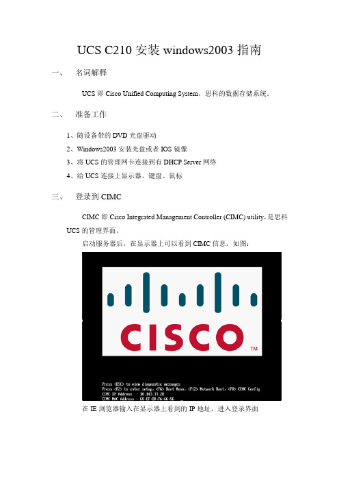
UCS C210安装windows2003指南一、名词解释UCS即Cisco Unified Computing System,思科的数据存储系统。
二、准备工作1、随设备带的DVD光盘驱动2、Windows2003安装光盘或者IOS镜像3、将UCS的管理网卡连接到有DHCP Server网络4、给UCS连接上显示器、键盘、鼠标三、登录到CIMCCIMC即Cisco Integrated Management Controller (CIMC) utility,是思科UCS的管理界面。
启动服务器后,在显示器上可以看到CIMC信息,如图:在IE浏览器输入在显示器上看到的IP地址,进入登录界面输入账号密码登录,默认账号为admin,默认密码为password。
四、CIMC中的操作CIMC界面如下:在CIMC中我们可以看到UCS型号,Serial Number,Server Status,CPU频率,内存容量,风扇,电源状态等众多信息,我们可以修改UCS的启动顺序,修改管理网卡的IP地址,启动/关闭/软重启/硬重启服务器,登录KVM控制台等众多操作。
五、配置raid1、ctrl + H 进入raid配置界面2、选择配置向导–>新建配置-> 下一步3、自定义配置4、添加磁盘到磁盘组5、确认6、下一步7、添加SPAN8、选择raid 级别,选择磁盘容量。
9、确认raid5 容量10、下一步11、确认12、完成六、登录KVM控制台在登录KVM控制台之前,请先在PC上安装有JRE(java运行环境),然后在CIMC中点击Launch KVM Console,弹出窗口提示该Web站点的证书无法验证,点击“是”继续,如图等待几秒钟后,系统会弹出一个Cisco Virtual KVM Console窗口,在这个窗口下,我们可以像控制自己电脑一样控制UCS,如图:七、虚拟光驱及软驱从Virtual KVM Console窗口我们可以将电脑上的文件、光驱虚拟成UCS的软驱、光驱,不过开始之前应该要先做一个准备工作。
UCS系统实施手册

UCS系统实施手册目录1.背景介绍 (4)2.Cisco统一计算系统部署过程 (6)2.1.UCS部署端口连接与IP地址分配 (6)2.2.Fabric interconnect初始配置 (6)2.3.UCSM管理界面登录 (7)2.4.端口属性设置 (9)2.5.建立Service Profile (11)2.5.1.直接创建单个Service Profile (12)2.5.1.1.设置Profile名称及UUID (13)2.5.1.2.设置存储属性 (13)2.5.1.3.设置网卡属性 (14)2.5.1.4.设置设备启动顺序 (15)2.5.1.5.关联Service Profile与刀片 (16)2.5.2.从template中生成Service Profile (16)2.5.2.1.配置MAC Pool (16)2.5.2.2.创建VLAN (18)2.5.2.3.创建Service Profile模板 (18)2.5.2.4.设置存储属性 (20)2.5.2.5.设置网卡属性 (21)2.5.2.6.创建服务配置文件并关联到刀片服务器 (23)1.背景介绍本文旨在介绍思科统一计算系统的核心特性能够如何简化服务器,网络以及虚拟环境的部署、增强管理、提供出色性能和安全性。
文章中介绍了该系统的统一阵列、统一内嵌管理、服务配置文件。
本文也介绍了如何配置统一阵列,如何产生和配置service profile,以及如何利用service profile快速配置服务器,同时也介绍如何实现高可用配置。
服务器虚拟化为世界各地的数据中心带来了众多优势,但同时它也向数据中心提出了挑战。
如果有统一的I/O配置和足够的带宽,在每台物理服务器上支持大量VM,则资源池的管理会较为容易。
资源池将能更快速地应对迅速变化的业务情况和工作负载,新服务器资源的添加能在几分钟内完成,然后设置并投入使用。
而无需通过数小时甚或数天繁琐、耗时且易于出错的人工配置,来准备服务器及其接口、固件和设置。
UCS 刀片服务器基本配置手册v1.0

UCS 刀片服务器基本配置手册V1.0liuxyn@2011.8.25目录0 UCS测试前准备工作 (1)确认现场是否具备测试环境 (1)电源环境 (1)网络环境 (1)设备拆箱所需工具 (1)检查设备及相关配件 (1)IP地址规划 (1)1 UCS Manager 密码重置 (2)2 UCS Manager删除配置 (6)3 UCS Manger 初始化配置 (8)4 UCS Manager web 管理 (9)5 配置上联口(GLC-T)千兆上联到网络交换机 (12)6配置Server Port (14)7 配置管理IP 使用KVM,Vmedia (15)8 配置Profile 模板 (15)9 根据profile模板生成profile (15)10 profile 关联刀片 (15)11 安装操作系统 (15)12 MDS 9124 系统恢复 (15)13 MDS 9124 初始化配置 (16)0 UCS测试前准备工作确认现场是否具备测试环境电源环境5108 刀片机箱电源线为16A 插头,确认用户现场有16A插口的插线板6120 功率350W左右5108 功率最大功率2500W ,实际功耗取决于刀片多少网络环境6120 接5108刀片机箱最少需要1个万兆口互联6120 上联到网络交换机千兆连接需要GLC-T模块连到网络交换机的千兆电口,或使用一对GLC-SX-MM模块+光纤跳线连到网络交换机的千兆SFP接口6120 上联到SAN交换机需要4Gb的SFP模块和光纤跳线(如果刀片上没有配硬盘、或需要和存储互联做相关测试,需要有MDS9124或其他厂商的SAN交换机)设备拆箱所需工具美工刀、平口螺丝刀、十字螺丝刀、老虎钳检查设备及相关配件电源线(10A/16A)模块(GLC-T或GLC-SX-MM),4Gb FC模块网线、光纤跳线IP地址规划UCS6120 管理口IP地址MDS9124 管理地址存储设备管理地址1刀片KVM管理地址ication OK3038 Mar 30 2011 04:19:33 115468140 Jan 13 2011 03:03:00plugin_file_is_excluded_from_exec_path: /boot/lib/libplugin_sysreg.so is excluded from linking plugin_file_is_excluded_from_exec_path: /boot/etc/ is excluded from linkingplugin_file_is_excluded_from_exec_path: /boot/etc/plugin_exclude.conf is excluded from linking plugin_file_is_excluded_from_exec_path: /boot/ is excluded from linkingplugin_file_is_excluded_from_exec_path: /boot/lib/ is excluded from linkingplugin_file_is_excluded_from_exec_path: /boot/lib/libplugin_sysreg.so.0.0.0 is excluded from linkingplugin_file_is_excluded_from_exec_path: /boot/lib/libplugin_sysreg.so.0 is excluded from linking plugin_file_is_excluded_from_exec_path: /boot/lib/libplugin_sysreg.so is excluded from linking plugin_file_is_excluded_from_exec_path: /boot/etc/ is excluded from linkingplugin_file_is_excluded_from_exec_path: /boot/etc/plugin_exclude.conf is excluded from linking 145680+1 records in145680+1 records outethernet end-host mode on CAFC end-host mode on CAn_port virtualizer mode.---------------------------------------------------------------ln: `/isan/etc/sysmgr.d//fcfwd.conf': File existsethernet end-host modeINIT: Switching to runlevel: 3INIT: Sending processes the TERM signalINIT: (boot)#Exporting directories for NFS kernel daemon...done.Starting NFS kernel daemon:rpc.nfsd.rpc.mountddone.Set name-type for VLAN subsystem. Should be visible in /proc/net/vlan/configAdded VLAN with VID == 4042 to IF -:muxif:----------------------enabled fc feature---------------------2011 Mar 30 04:30:33 %$ VDC-1 %$ %KERN-2-SYSTEM_MSG: Starting kernel... - kernel Executing Port Power On Tests.......System is coming up ... Please wait ...System is coming up ... Please wait ....System is coming up ... Please wait ....System is coming up ... Please wait ....System is coming up ... Please wait ....System is coming up ... Please wait ....System is coming up ... Please wait ...DoneSystem is coming up ... Please wait ...System is coming up ... Please wait ...System is coming up ... Please wait ...System is coming up ... Please wait ...5System is coming up ... Please wait ...2011 Mar 30 04:32:44 %$ VDC-1 %$ %VDC_MGR-2-VDC_ONLINE: vdc 1 has come onlineCisco UCS 6100 Series Fabric InterconnectSwitchi-A-A login: adminPassword:Cisco UCS 6100 Series Fabric InterconnectTAC support: /tacCopyright (c) 2009, Cisco Systems, Inc. All rights reserved.The copyrights to certain works contained herein are owned byother third parties and are used and distributed under license.Some parts of this software may be covered under the GNU PublicLicense or the GNU Lesser General Public License. A copy ofeach such license is available at/licenses/gpl.html and/licenses/lgpl.html2 UCS Manager删除配置清掉UCS配置信息,一切重头开始Cisco UCS 6100 Series Fabric InterconnectSwitchi-A-A login: adminPassword:Cisco UCS 6100 Series Fabric InterconnectTAC support: /tacCopyright (c) 2009, Cisco Systems, Inc. All rights reserved.The copyrights to certain works contained herein are owned byother third parties and are used and distributed under license.Some parts of this software may be covered under the GNU PublicLicense or the GNU Lesser General Public License. A copy ofeach such license is available at/licenses/gpl.html and/licenses/lgpl.html6Switchi-A-A# connect local-mgmtCisco UCS 6100 Series Fabric Interconnect3 UCS MangerPhysical Switch Mgmt0 IP Address=10.192.36.50 Physical Switch Mgmt0 IP Netmask=255.255.255.0批注 [liuxinyu17]: UCSmanager图形界面需要java环境,运行前请装好java115 配置上联口(批注 [liuxinyu18]: 定义与网络交换机互联的接口为uplink口批注 [liuxinyu19]: 接口默认启用的万兆,改为千兆146配置Server Port6-11 请参考《UCS 系统部署技术手册ver6》,《UCS_Vmware 测试模板v07-1》7 配置管理switch(boot)#copy tftp://192.168.1.1/ m9100-s2ek9-mz.4.2.3a.bin bootflash: switch(boot)# dirto skip the remaining dialogs.Would you like to enter the basic configuration dialog (yes/no): yesCreate another login account (yes/no) [n]: nConfigure read-only SNMP community string (yes/no) [n]: nConfigure read-write SNMP community string (yes/no) [n]: ySNMP community string : ciscoEnter the switch name : MDS9124-AContinue with Out-of-band (mgmt0) management configuration? (yes/no) [y]: Y Mgmt0 IPv4 address : 192.168.1.2Mgmt0 IPv4 netmask : 255.255.255.0Configure the default gateway? (yes/no) [y]: yIPv4 address of the default gateway : 192.168.1.254Configure advanced IP options? (yes/no) [n]: nEnable the ssh service? (yes/no) [y]: yType of ssh key you would like to generate (dsa/rsa) [rsa]:Number of rsa key bits <768-2048> [1024]:Enable the telnet service? (yes/no) [n]: yesEnable the http-server? (yes/no) [y]: yConfigure clock? (yes/no) [n]: yClock config format [HH:MM:SS Day Mon YYYY] :Enter clock config :14:20:40 15 August 201117Configure timezone? (yes/no) [n]: yesEnter timezone config :UTC 8Configure summertime? (yes/no) [n]: NConfigure the ntp server? (yes/no) [n]: nConfigure default switchport interface state (shut/noshut) [shut]: noshut Configure default switchport trunk mode (on/off/auto) [on]: Configure default switchport port mode F (yes/no) [n]: YConfigure default zone policy (permit/deny) [deny]: permitEnable full zoneset distribution? (yes/no) [n]: yConfigure default zone mode (basic/enhanced) [basic]:The following configuration will be applied:password strength-checksnmp-server community cisco rwswitchname MDS9124-Ainterface mgmt0ip address 192.168.1.2 255.255.255.0no shutdownip default-gateway 192.168.1.254ssh key rsa 1024 forcefeature sshfeature telnetfeature http-serverclock set 14:20:40 15 August 2011clock timezone UTC 8no system default switchport shutdownsystem default switchport trunk mode onsystem default switchport mode Fsystem default zone default-zone permitsystem default zone distribute fullno system default zone mode enhancedWould you like to edit the configuration? (yes/no) [n]: n18Use this configuration and save it? (yes/no) [y]: yError: There was an error executing at least one of the commands Please verify the following log for the command execution errors. Disabling ssh: as its enabled right now:deleting old rsa key.....generating rsa key(1024 bits)......generated rsa keyEnabling ssh: as it has been disabledMon Aug 15 14:20:40 UTC 2011Syntax error while parsing 'clock timezone UTC 8'Would you like to save the running-config to startup-config? (yes/no) [n]: y [########################################] 100%User Access VerificationMDS9124-A login: adminPassword:Cisco Nexus Operating System (NX-OS) SoftwareTAC support: /tacCopyright (c) 2002-2009, Cisco Systems, Inc. All rights reserved.The copyrights to certain works contained in this software areowned by other third parties and used and distributed underlicense. Certain components of this software are licensed underthe GNU General Public License (GPL) version 2.0 or the GNULesser General Public License (LGPL) Version 2.1. A copy of eachsuch license is available at/licenses/gpl-2.0.php and/licenses/lgpl-2.1.php19。
思科统一计算系统(Cisco UCS)容量规划和系统更新操作说明书
Capacity planning and system refresh Highlightsoperations are inseparable in data centers.optimum approach ties capacity expansion to the regular server refresh cycle,enabling IT to plan for demand and gain computing power in an intelligent manner.addition, built-in management functions provide exceptional visibility into and control over the entire infrastructureto streamline and coordinate administrative effort and eliminate common errors that delay deployment and disrupt operation.that supports blade and rack-mountservers to deliver scalability andperformance. A unified fabric supportedby a single, distributed virtual switchinterconnects all server resources.Servers and virtual machines areinterconnected equally and consistently,eliminating multiple layers of switching.This radically simplified architecturepacks more computing power intoless space while allowing IT to choosefrom a portfolio of servers to delivermassive computing density andcreates barriers to resource sharing and requires additional dedicated servers standing by to take over work in the event of a failure. Cisco UCS eliminates architectural silos through on-demand provisioning. Any computing resource potentially can be used for any application at any time. The infrastructure is “wire once” with all configuration managed through Cisco UCS Manager, eliminating the physical barriers that used to prevent applications from sharing resources.The intelligent infrastructure providedby Cisco UCS enables the entireconfiguration to be programmedthrough the intuitive Cisco UCSManager GUI and open standard XMLAPI. While other vendors supportthe automatic configuration of a fewparameters, Cisco UCS Managerincludes nearly 100 server identityparameters, eliminating the needfor manual tasks or the creationof scripts or the use of tools andagents that further complicate the ITenvironment. With Cisco UCS Manager,IT organizations can plan capacity on aholistic, data center wide basis, sharinginfrastructure across applications andharnessing it to best meet businesspriorities and service-level agreements(SLAs).Eliminating Networkand Cable Sprawl andComplexityUsing traditional implementations, theconnection of servers and storagesystems to growing numbers of userapplications and services requires extensive networking infrastructure. The resulting dramatically increased connectivity uses massive numbersof cables, creating significant management challenges. Administrators find it difficult to locate ports for new servers, to map and zone connectivity, and to track and locate sourcesof failures. In addition, this cable proliferation and sprawl requires vast numbers of switch ports and switches, which consume power and increase management complexity.Simplified Network Infrastructure Addressing the increasing need for better design and control, Cisco UCS provides greater network density with less cabling and complexity. Cisco’s unified fabric integrates Cisco UCS servers with a single high-bandwidth, low-latency network that supportsall system I/O. This fabric carries IP, storage, and management traffic over redundant 10 Gigabit Ethernet and Fibre Channel over Ethernet (FCoE) networks. This approach simplifies the architecture and reduces the number of I/O interfaces, cables, and access-layer switch ports that are required for traditional platforms. This unification can reduce network complexity by up to a factor of three, and the system’s wire-once network infrastructure increases agility and accelerates deployment with zero-touch configuration.All I/O traffic meets at a single specific and redundant point at which it is efficiently and consistently managed, increasing network security, simplifying management, and reducing errors. This approach eliminates blade-server and hypervisor-resident switching, condensing three network layersinto one and reducing capital andoperating costs. With the capability tointerconnect physical servers and virtualmachines as functional equivalents,the architecture delivers outstandingvisibility and control that lets virtualnetworks be managed with the samelevel of control as physical networks.Simplifying and AcceleratingServer Refresh OperationsThe ad hoc approach to expansionused in many data centers makes itdifficult to refresh and consolidate theenvironment. Cumbersome processesthat are tied to a complicated physicaland virtual infrastructure hamper IT’sability to install and configure newsystems and to rehost virtual serversand applications. Administrators mustperform tedious, repetitive, and time-consuming tasks that are often thesource of errors or result in inconsistentconfigurations or application ofcorporate policies and security. Thesedelays and inconsistencies affectapplication and service redeploymentand keep the IT organization fromsupporting real-time business needsand priorities.Automated Configuration for FastDeploymentCisco UCS simplifies and acceleratesserver refresh operations throughautomated configuration. The intelligentinfrastructure abstracts server identity,personality, and I/O connectivityfrom the hardware, enabling thesecharacteristics to be applied ondemand. Every aspect of a server’sconfiguration, from firmware revisionsand BIOS settings to network profiles,can be assigned through the system’sopen, documented, standards-basedXML API or Cisco UCS Manager GUI.As a result, server configurations canbe replicated easily. A new server canappear to the software stack just likethe old server, making server refreshoperations as simple as applying aCisco service profile and rebooting tolaunch the new system.Service Profiles Support PrestagingCisco service profile templatesestablish policy-based configurationfor server, network, and storageresources and can be used to logicallypreconfigure these resources evenbefore they are deployed in the datacenter. By preparing service profiles inadvance, administrators can prestageIP addresses and storage world-widenames (WWNs) and attach mappingsto components. In addition, CiscoUCS blade server slots can be set toautomatically configure blade serversupon insertion with network andstorage settings that are in compliancewith the policies established byappropriate data center administrators.Configuration also can be performed asa manual process as needed, with fullserver identity parameter control andintegration with network and storageresources.Making Virtualization MoreEffectiveAs data centers reach the limits oftheir physical capacity, virtualizationstrategies to consolidate workloadsonto fewer resources can be importantaids. Yet the virtualization effortsdeployed by many data centers haveresulted in new challenges. The useof blade server chassis-resident networks and hypervisor-resident software switches creates a complex set of switching layers that makes managing, debugging, and securing virtual networks difficult. Server sprawl continues unabated, with a proliferation of physical servers added to the environment to support a vast arrayof virtual machines, delivering ever-increasing numbers of applications and services. With a patchworkof technologies in place, physicaland virtual systems are deployed, connected, and managed in many different ways, further complicating infrastructure administration and management.More Virtualization at Less Cost Cisco UCS enables IT organizations to meet ever-increasing guest operating system memory footprint demands on fewer physical servers. The system’s high density, high-performance design,including Cisco Extended MemoryTechnology, increases consolidationratios for 2-socket servers, saving thecapital, operating, physical space, andlicensing costs of running virtualizationsoftware on larger, 4-socket servers.With support for up to 1 terabyte(TB) of high-speed memory in a2-socket server, organizations canhost applications using less-expensiveservers without sacrificing performance.As a result, IT organizations can putmore virtual machines on each server,reducing physical server sprawl andbreaking down management silos.Greater Visibility and ControlIT organizations need to simplifyphysical infrastructure to break downsilos and make the data center moreeffective. They also need to improvetheir virtual infrastructure so that it canbe managed just as simply and easilyas it scales. Traditional virtualizedenvironments require the use ofsoftware-based switches that reside inthe hypervisor. The insertion of a newswitch can cause a loss of visibility fromthe physical network interface to virtualmachines. The result is a network ofvirtual machines with connection pointsthat cannot be seen. If connectionscannot be seen, they cannot bemanaged or secured.Cisco UCS uses virtualization-optimizednetworking that makes managingvirtual machine networks equivalentto managing physical networks.Cisco FEX Technology architectureextends the visibility of network andstorage access all the way to individualvirtual machines, without hypervisorintervention. These connectionsterminate in the fabric interconnects asvirtual ports that are managed exactlythe same way as physical ports. VirtualDistributed Virtual Blade Chassis+=+Servers Fabric Interconnects Fabric ExtendersFigure 2. Cisco UCS Combines Blade and Rack Servers, Networking, and Storage Resources in a Distributed, Virtual Blade Chassis with a Single, Redundant Point of Connectivity and ManagementAmericas Headquarters Cisco Systems, Inc. San Jose, CA Asia Pacific Headquarters Cisco Systems (USA) Pte. Ltd. Singapore Europe HeadquartersCisco Systems International BV Amsterdam, The NetherlandsCisco has more than 200 offices worldwide. Addresses, phone numbers, and fax numbers are listed on the Cisco Website at /go/offices .Cisco and the Cisco logo are trademarks or registered trademarks of Cisco and/or its affiliates in the U.S. and other countries. To view a list of Cisco trademarks, go to this network interface cards (vNICs) are attached to virtual machines, and their network profiles remain constant and attached, even when virtual machines are moved from one physical server to a different server, enhancing mobility and security. Workloads can bemigrated between physical devices, optimizing performance and maintaining security protocols and policies, without requiring intervention by the network team to reset quality of service (QoS) and security for each migrated virtual machine.The Cisco UCS design results in a distributed, virtual blade chassis that combines the performance and management of physical networks with the scalability of virtual networks. Administrators can use familiar management models on virtualmachines and take advantage of built-in automation and intelligence to gain outstanding visibility into, and control over, virtualized environments. Forexample, bandwidth can be flexibly and dynamically managed with a QoS policy to help guarantee bandwidth for priority workloads running in virtual machines, while also helping ensure that overall bandwidth is used efficiently and not wasted (Figure 2).More Capacity and Reduced ComplexityData center infrastructure management has become a complicated challenge. The proliferation of management points and the physical devices to which they are connected has resulted in a new kind of sprawl that must be contained. Typically, administrators have to use a variety of element managers to interact with dozens of management touch points that are distributedacross multiple servers, blade chassis, racks, networking, and storageresources. Unfortunately, most vendors attempt to solve this management challenge by introducing additional layers of management tools that are patched together into an accidental architecture that creates more work for administrators.Less Complex and Easier to Manage The unified infrastructure andarchitecture-by-design approach of Cisco UCS delivers the scalability needed to perform capacity planning and refresh activities without the complexity of traditional systems. The dramatic reduction in the number of physical components results in a system that makes effective use of limited space, power, and cooling by deploying less infrastructure to perform the same, or even more, work.The system’s unified fabric results in fewer NICs, host bus adapters (HBAs), cables, and upstream switch ports, and eliminates the need for a parallel Fibre Channel end-to-end network. Traditional blade server chassis resident switches are replaced by a low-cost, low-power, zero-management fabric extender that enables the entire system to scale across multiple blade chassis and rack servers without addingmanagement points. All hardware and software components are managed through the unified, embedded Cisco UCS Manager to improve operation efficiency with seamless scaling.ConclusionDeployment of Cisco UCS systems enables data centers to reap the benefits of a simplified infrastructure. By consolidating from a large-footprint rack or complex and network-intensive blade environment to Cisco UCS, IT organizations can reduce the footprint and complexity of the entire datacenter. Server refresh and consolidationoperations become easy, scalable, and repeatable exercises that optimize data center investments.Learn MoreTo learn more about Cisco UCS, visit /go/ucs or contact your local account representative.。
Cisco UCS C240 M4服务器安装和维护指南说明书
A-1Cisco UCS C240 M4 Server Installation and Service GuideOL-32474-01A P P E N D I XAServer SpecificationsThis appendix lists the technical specifications for the server and includes the following sections:•Physical Specifications, page A-1 •Power Specifications, page A-2 •Environmental Specifications, page A-6Physical SpecificationsTable A-1 lists the physical specifications for the server.T able A-1Physical SpecificationsDescription Specification Height3.4 in. (8.70 cm)Width (including slam latches)19.0 in. (48.26 cm)Depth (length)Depth, including slam latches and power supply handles29.0 in. (73.70 cm) 31.5 in. (80.00 cm)Maximum Weight (fully loaded)SFF 8-drive: 52.9 lb. (24.0 Kg)SFF 16-drive: 58.9 lb. (26.7 Kg)SFF 24-drive: 62.7 lb. (28.4 Kg)LFF 12-drive: 67.5 lb. (30.6 Kg)Appendix A Server Specifications Power SpecificationsPower SpecificationsThe power specifications for the power supply options are listed in the following sections:•650 W AC Power Supply, page A-2•1200 W AC Power Supply, page A-3•1400 W AC Power Supply, page A-4•930 W DC (Version 2) Power Supply, UCSC-PSU2V2-930DC, page A-5•930 W DC (Version 1) Power Supply, UCSC-PSU-930WDC, page A-5You can get more specific power information for your exact server configuration by using the Cisco UCSPower Calculator:650 W AC Power SupplyTable A-2 lists the specifications for each 650 W AC power supply(Cisco part number UCSC-PSU2V2-650W=).T able A-2650 W AC Power Supply SpecificationsDescription SpecificationAC input voltage Nominal range: 100–120 VAC, 200–240 VAC(Range: 90–132 VAC, 180–264 VAC)AC input frequency Nominal range: 50 to 60Hz(Range: 47–63 Hz)Maximum AC input current7.6 A at 100 VAC3.65 A at 208 VACMaximum input volt-amperes760 VA at 100 VACMaximum output power per PSU650 WMaximum inrush current35 A (sub-cycle duration)Maximum hold-up time12 ms at 650 WPower supply output voltage12 VDCPower supply standby voltage 3.3 VDCEfficiency rating Climate Savers Platinum Efficiency (80Plus Platinum certified)Form factor RSP1Input connector IEC60320 C14Cisco UCS C240 M4 Server Installation and Service GuideOL-32474-01Appendix A Server SpecificationsPower Specifications1200 W AC Power SupplyTable A-3 lists the specifications for each 1200 W AC power supply(Cisco part number UCSC-PSU2V2-1200W=).T able A-31200 W AC Power Supply SpecificationsDescription SpecificationAC input voltage Nominal range: 100–120 VAC, 200–240 VAC(Range: 90–132 VAC, 180–264 VAC)AC input frequency Nominal range: 50 to 60Hz(Range: 47–63 Hz)Maximum AC input current11 A at 100 VAC7 A at 200 VACMaximum input volt-amperes1456 VAMaximum output power per PSU800 W at 100–120 VAC1200 W at 200–240 VACMaximum inrush current35 A (sub-cycle duration)Maximum hold-up time12 ms at 1200 WPower supply output voltage12 VDCPower supply standby voltage12 VDCEfficiency rating Climate Savers Platinum Efficiency (80Plus Platinum certified)Form factor RSP1Input connector IEC60320 C14Cisco UCS C240 M4 Server Installation and Service Guide OL-32474-01Appendix A Server Specifications Power Specifications1400 W AC Power SupplyTable A-2 lists the specifications for each 1400 W AC power supply(Cisco part number UCSC-PSU2V2-1400=).T able A-41400 W AC Power Supply SpecificationsDescription SpecificationAC input voltage Nominal range: 200–240 VAC(Range: 180–264 VAC)AC input frequency Nominal range: 50 to 60Hz(Range: 47–63 Hz)Maximum AC input current8.5 A at 200 VACMaximum input volt-amperes1700 VAMaximum output power per PSU1400 W at 200–240 VACMaximum inrush current<30 A at 25° C (sub-cycle duration)Maximum hold-up time12 ms at 1200 WPower supply output voltage12 VDCPower supply standby voltage12 VDCEfficiency rating Climate Savers Platinum Efficiency (80Plus Platinumcertified)Form factor RSP1Input connector IEC60320 C14Cisco UCS C240 M4 Server Installation and Service GuideOL-32474-01Appendix A Server SpecificationsPower Specifications930 W DC (Version 2) Power Supply, UCSC-PSU2V2-930DCTable A-6 lists the specifications for each 930 W DC power supply(Cisco part number UCSC-PSU2V2-930DC=).T able A-5930 W DC Version 2 Power Supply SpecificationsDescription SpecificationDC input voltage range Nominal range: –48 to –60 VDC nominal(Range: –40 to –60 VDC)Maximum DC input current28 A at –40 VDCMaximum input W1104 WMaximum output power per PSU930 WMaximum inrush current35 A (sub-cycle duration)Maximum hold-up time 5 ms at 930 WPower supply output voltage12 VDCPower supply standby voltage12 VDCEfficiency rating> 92% at 50% loadForm factor RSP1 (C-Series 2U and 4U servers)Input connector Fixed 3-wire block930 W DC (Version 1) Power Supply, UCSC-PSU-930WDCTable A-6 lists the specifications for each 930 W DC power supply(Cisco part number UCSC-PSU-930WDC=).T able A-6930 W DC Version 1 Power Supply SpecificationsDescription SpecificationDC input voltage range Nominal range: –48 to –60 VDC nominal(Range: –40 to –60 VDC)Maximum DC input current23 A at –48 VDCMaximum input W1104 WMaximum output power per PSU930 WMaximum inrush current35 A (sub-cycle duration)Maximum hold-up time8 ms at 930 WPower supply output voltage12 VDCPower supply standby voltage12 VDCEfficiency rating> 92% at 50% loadForm factor RSP1 (C-Series 2U and 4U servers)Input connector Removable connector block UCSC-CONN-930WDC=Cisco UCS C240 M4 Server Installation and Service Guide OL-32474-01Cisco UCS C240 M4 Server Installation and Service GuideOL-32474-01Appendix A Server SpecificationsEnvironmental SpecificationsEnvironmental SpecificationsTable A-7 lists the environmental specifications for the server.T able A-7Environmental SpecificationsDescriptionSpecificationTemperature, operating41 to 95°F (5 to 35°C)Derate the maximum temperature by 1°C per every 305 meters of altitude above sea level.Temperature, nonoperating(when the server is in storage or is transported)–40 to 149°F (–40 to 65°C)Humidity (RH), operating 10 to 90%Humidity, non-operating 5 to 93%Altitude, operating 0 to 10,000 feet Altitude, nonoperating(when the server is in storage or is transported)0 to 40,000 feetSound power level Measure A-weighted per ISO7779 LwAd (Bels)Operation at 73°F (23°C)5.8Sound pressure levelMeasure A-weighted per ISO7779 LpAm (dBA)Operation at 73°F (23°C)43。
Cisco UCS C260服务器安装与维护指南说明书
B-1Cisco UCS C260 Server Installation and Service GuideOL-24342-01A P P E N D I XBPower Cord SpecificationsThis appendix provides supported power cable specifications.Supported Power Cords and PlugsEach power supply has a separate power cord. Standard power cords or jumper power cords are available for connection to the server. The jumper power cords, for use in racks, are available as an optional alternative to the standard power cords.NoteOnly the approved power cords or jumper power cords provided with the server are supported.Table B-1 lists the power cords for the server power supplies.T able B-1Supported Power Cords for the ServerDescriptionLengthPower CordReference Illustration Feet Meters CAB-250V-10A-ARPower Cord, 250 VAC 10 A IRAM 2073 Plug Argentina8.22.5Figure B-1CAB-9K10A-AU250 VAC 10 A 3112 Plug, Australia8.2 2.5Figure B-2CAB-250V-10A-CNPower Cord, 250 VAC 10 A GB 2009 Plug China8.2 2.5Figure B-3CAB-9K10A-EUPower Cord, 250 VAC 10 A M 2511 Plug Europe8.2 2.5Figure B-4CAB-250V-10A-IDPower Cord, 250 VAC 16A EL-208 Plug South Africa, United Arab Emirates, India 8.2 2.5Figure B-5CAB-250V-10A-ISPower Cord, 250 VAC 10 A SI32 Plug Israel8.2 2.5Figure B-6Cisco UCS C260 Server Installation and Service GuideOL-24342-01Appendix B Power Cord SpecificationsSupported Power Cords and PlugsCAB-9K10A-ITPower Cord, 250 VAC 10 A CEI 23-16 Plug Italy8.22.5Figure B-7CAB-9K10A-SWPower Cord, 250 VAC 10 A MP232 Plug Switzerland8.2 2.5Figure B-8CAB-9K10A-UKPower Cord, 250 VAC 10 A BS1363 Plug (13 A fuse)United Kingdom8.2 2.5Figure B-9CAB-AC-250V/13APower Cord, 250 VAC 13 A IEC60320 Plug North America6.62.0Figure B-10CAB-N5K6A-NAPower Cord, 250 VAC 13 A NEMA 6-15 Plug,North America8.2 2.5Figure B-11CAB-9K12A-NAPower cord, 125 VAC, 13 A, NEMA 5-15 Plug North America8.2 2.5Figure B-12CAB-C13-CBNCabinet Jumper Power Cord, 250 VAC 10 A, C13-C14 Connectors2.20.68Figure B-13CAB-C13-C14-2MCabinet Jumper Power Cord, 250 VAC 10 A, C13-C14 Connectors6.6 2.0Figure B-14CAB-C13-C14-ACCabinet Jumper Power Cord, 250 VAC 10 A, C13-C14 Connectors9.8 3.0Figure B-15T able B-1Supported Power Cords for the Server (continued)DescriptionLengthPower CordReference Illustration Feet MetersB-3Cisco UCS C260 Server Installation and Service GuideOL-24342-01Appendix B Power Cord SpecificationsSupported Power Cords and PlugsB-4Cisco UCS C260 Server Installation and Service GuideOL-24342-01Appendix B Power Cord SpecificationsSupported Power Cords and PlugsB-5Cisco UCS C260 Server Installation and Service GuideOL-24342-01Appendix B Power Cord SpecificationsSupported Power Cords and PlugsPlug: I/3G (CEI 23-16)Connector C15M(EN60320/C15 )Cordset rating: 10 A, 250 V Length: 8 ft 2 in. (2.5 m)186575B-6Cisco UCS C260 Server Installation and Service GuideOL-24342-01Appendix B Power Cord SpecificationsSupported Power Cords and PlugsB-7Cisco UCS C260 Server Installation and Service GuideOL-24342-01Appendix B Power Cord SpecificationsSupported Power Cords and PlugsAppendix B Power Cord Specifications Supported Power Cords and PlugsCisco UCS C260 Server Installation and Service GuideOL-24342-01。
UCS系统配置指南
配置管理IP,实现KVM连接,使用vMedia
映射本地iso文件
配置管理IP信息,登陆用户
登陆UCS manager界面
配置互联阵列到刀箱连接 物理连接阵列扩展器和互联交换机,将交换机上端口配置为server port
配置完成后即可在管理界面中认到刀箱及刀片信息
配置后端连接存储端口 若连接光纤交换机,端口类型设为FC Uplink Port 注意VSAN的设置要和光纤交换机一致
在Server>Service Profile Templates中右键Create
创建Service Profile模板
在“Identify Service Profile Templates” 屏幕,在“Name” 项, 输入规划好的模板名称,选择“Initial Template”,单击“Next”。
点击导航窗口的“admin”页,点击“Management IP Pool(extmgmt)”项,再点击工作窗口的“Create Block of IP Addresses”,
注意ip地址是UCS随机分配。
配置管理IP,实现KVM连接,使用vMedia
点击导航窗口的“Equipment”页,点击“Servers”,选择一个服 务器,并点击工作窗口的“chassis”页,选择“KVM Consol”
定义资源池-UUID Pool
在导航窗口,选择“server”页,点击“Pools”项,点击并扩展“Root”项 右键点击“ UUID Suffix Pool”然后选择“ Create UUID Suffix Pool”。
定义资源池-MAC Pool
在导航窗口,选择“LAN”页,点击“Pools”项,点击并扩展“Root”项, 右键点击“ MAC Pools”然后选择“ Create MAC Pool”。
- 1、下载文档前请自行甄别文档内容的完整性,平台不提供额外的编辑、内容补充、找答案等附加服务。
- 2、"仅部分预览"的文档,不可在线预览部分如存在完整性等问题,可反馈申请退款(可完整预览的文档不适用该条件!)。
- 3、如文档侵犯您的权益,请联系客服反馈,我们会尽快为您处理(人工客服工作时间:9:00-18:30)。
Cisco Unified Computing System(统一计算系统)思科UCS安装部署手册目录目录1概述 (3)编写目的 (3)文档适用人员 (3)实施原则 (3)2网络设计 (5)UCS系统网络设计(可根据实际情况修改) (5)3实施方案设计 (7)控制器设备命名参数表 (7)设备登录信息表 (7)IP地址规划表 (7)硬件配置信息 (8)3.4.1Fabric Interconnect mode信息表 (8)3.4.2Fabric Interconnect port角色信息表 (9)3.4.3设备连接信息表 (11)3.4.4Port Channel信息表 (13)服务配置信息 (13)3.5.1Service profile信息表 (13)3.5.2MAC pool信息表 (14)3.5.3WWNN pool信息表 (15)3.5.4WWPN pool信息表 (15)3.5.5UUID Suffix pool信息表 (15)3.5.6VLAN信息表 (15)策略信息 (16)3.6.1Local Disk (16)3.6.2Boot策略 (16)4实施过程 (18)6248XP初始化 (18)4.1.16248XP接线准备 (18)4.1.26248XP 初始化6248XP-A (18)4.1.36248XP初始化6248XP-B (19)4.1.4登陆UCS Manager (19)刀箱发现 (20)4.2.1配置刀箱发现策略 (20)4.2.2配置存储上联口 (20)4.2.3配置网络上联口 (22)4.2.4配置刀箱下联口 (23)4.2.5刀箱发现状态 (23)刀片管理IP配置 (24)资源池和策略配置 (25)4.4.1UUID Pool (25)4.4.2MAC Pool (28)4.4.3WWNN POOL (29)4.4.4WWPN Pool (31)4.4.5Vlan定义 (34)4.4.6Local Disk Raid策略 (36)4.4.7Boot启动策略 (37)创建Service Profile(根据现场实施画面更改) (39)关联Service Profile到指定的刀片服务器上 (48)刀片服务器的操作系统安装 (51)4.7.1KVM Console (51)4.7.2操作系统安装 (55)4.7.3操作系统驱动安装 (57)1概述编写目的本文的是铁姆肯虚拟化平台UCS部分的项目技术实施的详细描述和规划,撰写本文的目的是在实际实施工作前,将所有实施步骤、方法和各方需完成的任务明确。
文档适用人员本文档资料主要面向负责铁姆肯虚拟化平台UCS服务器实施项目的设计和实施的技术人员,管理人员。
实施原则➢实施步骤的完整性,对于每一个实施步骤各方所需要执行的动作有明确的规定,有精确的时间顺序安排,对每一个动作有详细的操作步骤,对每一个执行的动作都有相应的检查是否完成的步骤,达到任何一个只要具有实际实施经验的工程师都能按实施方案完成执行动作。
➢详细描述实施方案的风险和局限性,明确使用实施方案所应承担的风险和将导致的后果。
➢在实施前需要各参与单位和人员最终确认实施方案的正确性、明确各方所执行的动作和担负的责任。
➢对于检查实施方案的每一个阶段是否达到方案要求,需要有每一阶段的测试内容,明确那些测试在指定时间点不能完成或完成后测试结果不正确的情况下需要采用网络回退方案,不再执行实施方案的下一个执行动作或不进入下一个实施阶段。
➢为了尽量减少业务中断时间,所有测试和改造工作都在重要业务停止时进行,同时对于参与测试的设备原有数据都要备份。
➢网络调整、应用切换方案在制定时要和所相关应用部门进行充分的沟通,要向应用部门介绍详细的切换过程,切换步骤、切换时间要征得相关应用部门的同意。
➢网络调整、应用切换实施时要有应用部门的人员在场,负责对应用进行验证,并得出结论。
2 网络设计UCS 系统网络设计(可根据实际情况修改)刀箱背部10GB SFP+连接线1GB 电口网线8GB FiberMidea-5B-R3L01-FI-ASAN Switch A2204XP2208XP2204XP2208XPSAN Switch B存储MGMTMGMT刀箱背部1GB SFP +连接线Midea-5B-R3L01-FI-B …7台Eth2/1-Eth2/2Eth1/1-Eth1/14Eth2/1-Eth2/2Eth2/15-Eth2/16Eth2/15-Eth2/16Eth1/1-Eth1/14说明:➢ 每个UCS5108刀片机箱通过两个I/O 模块,每个模块X 条10G 链路(2204XP 上联或2208XP 上联)分别连接到两台6248管理设备。
➢ 两台6248之间通过两条100/1000M 以太网线实现管理配置同步,之间不走业务数据。
➢ 每个6248配置2个10GB 网络上联接口,配置port channel 连接到核心的Catalyst 交换机上。
➢ 每个6248的最后两个端口FC2/15、FC2/16配置成FC Port 上联至存储交换机。
➢ 每个6248的管理口通过100/1000M 以太网网线接入到管理交换机,实现带外管理。
➢每个6248的取一个10G uplink,通过GLC-T模块,100/1000M以太网网线接入到管理交换机,接入虚拟化平台的管理网络,主要运行vCenter 流量。
3实施方案设计控制器设备命名参数表设备设备命名Cisco UCS 6248XP-ACisco UCS 6248XP-BCisco UCS 6248XP-cluster设备登录信息表设备名(5B机房)用户名密码UCSM adminI P地址规划表设备(5B机房)地址规划子网掩码网关6248XP Virtual IP Address6248XP A IP Address6248XP B IP Address刀片机箱刀片槽位管理IP 子网掩码网关机箱1 1 255.255.255.02 255.255.255.03 255.255.255.04 255.255.255.05 255.255.255.06 255.255.255.07 255.255.255.08 255.255.255.0机箱2 1 255.255.255.02 255.255.255.03 255.255.255.04 255.255.255.05 255.255.255.06 255.255.255.07 255.255.255.08 255.255.255.0机箱3 1 255.255.255.02 255.255.255.03 255.255.255.04 255.255.255.05 255.255.255.06 255.255.255.07 255.255.255.08 255.255.255.0硬件配置信息3.4.1Fabric Interconnect mode信息表Mode Nmae(5B机房)Mode Comment Ethernet Ethernet End Host 与Catalyst交换机互联FC FC End Host 与存储交换机互联Mode Nmae(6C机房)Mode Comment Ethernet Ethernet End Host 与Catalyst交换机互联FC FC End Host 与存储交换机互联3.4.2Fabric Interconnect port角色信息表设备接口(5B机房)对端接口Cisco UCS 6248XP-ACisco UCS 6248XP-A- E1/1 server portCisco UCS 6248XP-A- E1/2 server portCisco UCS 6248XP-A- E1/3 server portCisco UCS 6248XP-A- E1/4 server portCisco UCS 6248XP-A- E1/5 server portCisco UCS 6248XP-A- E1/6 server portCisco UCS 6248XP-A- E1/7 server portCisco UCS 6248XP-A- E1/8 server portCisco UCS 6248XP-A- E1/9 server portCisco UCS 6248XP-A- E1/10 server portCisco UCS 6248XP-A- E1/11 server portCisco UCS 6248XP-A- E1/12 server portCisco UCS 6248XP-A – E1/13 server portCisco UCS 6248XP-A- E1/14 server portCisco UCS 6248XP-A- E2/1 Eth Uplink portCisco UCS 6248XP-A – E2/2 Eth Uplink portCisco UCS 6248XP-A- E2/15 FC Uplink portCisco UCS 6248XP-A- E2/16 FC Uplink port Cisco UCS 6248XP-BCisco UCS 6248XP-B- E1/1 server portCisco UCS 6248XP-B- E1/2 server portCisco UCS 6248XP-B- E1/3 server portCisco UCS 6248XP-B- E1/4 server portCisco UCS 6248XP-B- E1/5 server portCisco UCS 6248XP-B- E1/6 server portCisco UCS 6248XP-B- E1/7 server portCisco UCS 6248XP-B- E1/8 server portCisco UCS 6248XP-B- E1/9 server portCisco UCS 6248XP-B- E1/10 server portCisco UCS 6248XP-B- E1/11 server portCisco UCS 6248XP-B- E1/12 server portCisco UCS 6248XP-B – E1/13 server portCisco UCS 6248XP-B- E1/14 server portCisco UCS 6248XP-B- E2/1 Eth Uplink portCisco UCS 6248XP-B – E2/2 Eth Uplink portCisco UCS 6248XP-B- E2/15 FC Uplink portCisco UCS 6248XP-B- E2/16 FC Uplink port设备接口(6C机房)对端接口Cisco UCS 6248XP-ACisco UCS 6248XP-A- E1/1 server portCisco UCS 6248XP-A- E1/2 server portCisco UCS 6248XP-A- E1/3 server portCisco UCS 6248XP-A- E1/4 server portCisco UCS 6248XP-A – E1/13 Eth Uplink portCisco UCS 6248XP-A- E1/14 Eth Uplink portCisco UCS 6248XP-A – E1/15 Eth Uplink portCisco UCS 6248XP-A- E1/16 Eth Uplink portCisco UCS 6248XP-A- E1/31 FC Uplink portCisco UCS 6248XP-A- E1/32 FC Uplink portCisco UCS 6248XP-BCisco UCS 6248XP-A- E1/1 server portCisco UCS 6248XP-A- E1/2 server portCisco UCS 6248XP-A- E1/3 server portCisco UCS 6248XP-A- E1/4 server portCisco UCS 6248XP-A – E1/13 Eth Uplink portCisco UCS 6248XP-A- E1/14 Eth Uplink portCisco UCS 6248XP-A – E1/15 Eth Uplink portCisco UCS 6248XP-A- E1/16 Eth Uplink portCisco UCS 6248XP-A- E1/31 FC Uplink portCisco UCS 6248XP-A- E1/32 FC Uplink port 3.4.3设备连接信息表设备接口(5B机房)本端接口对端接口Cisco UCS 6248XP-A E1/1 Chassis1-FEX-1/1 E1/2 Chassis1-FEX-1/2 E1/3 Chassis2-FEX-1/1 E1/4 Chassis2-FEX-1/2 E1/5 Chassis3-FEX-1/1 E1/6 Chassis3-FEX-1/2 E1/7 Chassis4-FEX-1/1 E1/8 Chassis4-FEX-1/2 E1/9 Chassis5-FEX-1/1 E1/10 Chassis5-FEX-1/2 E1/11 Chassis6-FEX-1/1 E1/12 Chassis6-FEX-1/2 E1/13 Chassis7-FEX-1/1E1/14 Chassis7-FEX-1/2E2/1 上联网络交换机E2/2 上联网络交换机E2/15 上联存储交换机E2/16 上联存储交换机L1 Cisco UCS 6248XP-B L1 L2 Cisco UCS 6248XP-B L2 M0 上联管理交换机Cisco UCS 6248XP-B E1/1 Chassis1-FEX-2/1E1/2 Chassis1-FEX-2/2E1/3 Chassis2-FEX-2/1E1/4 Chassis2-FEX-2/2E1/5 Chassis3-FEX-2/1E1/6 Chassis3-FEX-2/2E1/7 Chassis4-FEX-2/1E1/8 Chassis4-FEX-2/2E1/9 Chassis5-FEX-2/1E1/10 Chassis5-FEX-2/2E1/11 Chassis6-FEX-2/1E1/12 Chassis6-FEX-2/2E1/13 Chassis7-FEX-2/1E1/14 Chassis7-FEX-2/2E2/1 上联网络交换机E2/2 上联网络交换机E2/15 上联存储交换机E2/16 上联存储交换机L1 Cisco UCS 6248XP-A L1L2 Cisco UCS 6248XP-A L2M0 上联管理交换机3.4.4Port Channel信息表设备(5B机房) Port Channel 端口备注Cisco UCS 6248XP-A 1 E2/12*10GB网络上联端口E2/2Cisco UCS 6248XP-B 1 E2/12*10GB网络上联端口E2/2设备(6C机房) Port Channel 端口备注Cisco UCS 6248XP-A 1 E1/134*1GB网络上联端口E1/14E1/15E1/16Cisco UCS 6248XP-B 1 E1/134*1GB网络上联端口E1/14E1/15E1/16服务配置信息3.5.1Service profile信息表Server Service profile Slot Template Boot Chassis1Server1 chassis-1/slot-1Server2 chassis-1/slot-2Server3 chassis-1/slot-3Server4 chassis-1/slot-4Server5 chassis-1/slot-5Server6 chassis-1/slot-6Server7 chassis-1/slot-7Server8 chassis-1/slot-8Chassis2Server1 chassis-2/slot-1Server2 chassis-2/slot-2Server3 chassis-2/slot-3Server4 chassis-2/slot-4Server5 chassis-2/slot-5Server6 chassis-2/slot-6Server7 chassis-2/slot-7Server8 chassis-2/slot-83.5.2MAC pool信息表MAC pool size3.5.3WWNN pool信息表WWNN Name Size3.5.4WWPN pool信息表WWPN Name Size3.5.5UUID Suffix pool信息表UUID Suffix pool size0000-500000000001-0000-5000000000200 5F-UUID-Pool0000-500000000201-0000-50000000004003.5.6VLAN信息表VLAN Name VLAN ID Comment VLAN_MGMT_21 670VLAN_WEB_0 601VLAN_WEB_1 651VLAN_APP_8 602VLAN_APP_9 652VLAN_APP_10 662VLAN_APP_11 663VLAN_APP_12 664VLAN_DB_16 603VLAN_DB_17 653VLAN_DB_18 654VLAN_LDAP_15 611VLAN_MAIL_7 610VLAN_MES_193 612VLAN_MES_224 613VLAN_MES_225 615VLAN_MGMT_202 609VLAN_MGMT_22 671策略信息3.6.1Local DiskName Disk Disk policy CommentRaid1 2块硬盘Raid 1 Mirred 所有服务器硬盘做Raid1策略3.6.2Boot策略name use Comment所有服务器设置CD/DVD启动优先,CD-HDD 启动顺序HDD其次4实施过程6248XP初始化4.1.16248XP接线准备用2根100/1000Mb的网线,分别对应接在两台6248XP的L1、L2心跳线接口上。