pol系列暖通控制器综合说明
APFR功率因数控制器使用说明及异常处理
cosΦ:在交流电路中,电压与电流之间的相位差(Φ)的余弦叫做功率因数,用符号cosΦ表示,在数值上,功率因数是有功功率和视在功率的比值,即cosΦ=P/S。
目标值0.7—1.0c/k值:C/K值为功率因素的敏感度。
通常设定为电容的第一步级(电容器第一段)的2/3电流量,表示要切换投入或切离电容器步级(电容器段数)的功率因素控制器的电流门槛。
可设定为0.01—0.99。
精成用的0.075,。
PHASE:中文意思相。
指相依位,按照控制器接线图连接,相位依为90°(预设值)。
可以自动或手动调整。
精成用的90。
DELAY: 中文意思延迟。
各步级(电容器段数)间的切换延迟时间。
预设值为40S,可设定为1—120S之间。
精成用的45。
OUT: 输出。
表示实际的输出数量,以内型而定,可设定1—12.。
可自动(AUTO SET)设定或手动设定(MAN SET-OUTPUT)。
设置成6或12.SEQUENCE: 顺序。
控制器所执行的切换顺序。
序列类型。
SET: set up PTCT ratio and parameters 设置PTCT比例和参数。
Increase set value :增加设定值。
Decrcase set value:减少设定值。
A P F R故障指引发布时间:2010/5/14 狀況1:沒有螢屏燈號處理方法:檢查VS.與220或380端子間電壓是否正常?若不正常或無電壓則可能是配線錯誤或FUSE不良;若正常則APFR故障。
狀況2:電壓指示異常處理方法:1)檢查VT端子配線是否正確,電壓指示為VS與VT間電壓,若沒接或錯接則無法指示。
2)PT設定錯誤,低壓用戶請設定PT=1,此設定僅供PT二次電壓110V之高壓用戶使用。
若是440/480V用戶,請使用自偶變壓器降壓220V接入VS及220V間端子間,VT端子則直接接440/480V即可,PT設定=1,VT端子可接600V以下。
狀況3:電流指示異常處理方法:1)CT設定不正確,如500:5應設定為100倍2)CT配線錯誤,若與其他設備共用CT應串接或電流未接,開路狀況4:電流讀數與電流錶或鉤表不同處理方法:本APFR電流讀數為True RMS真均方根值即含諧波量的電流,一般鉤表無法讀取非正弦波的電流,而電流幾乎都不是正弦波,請購買有注明Ture RMS 標示的鉤表參考使用狀況5:P.F.指示異常處理方法:1)檢查CT安裝位置是否正確(注意:CT應該與VS,VT端子的電壓安裝在不同線(相)上,CT必須接在負載及電容器之前)2)P.F.與其他儀錶不同原因:一般儀器是取電壓與電流之相位計算P.F.,此法較簡單,但不適用於目前廣泛使用的諧波負載,大部份的APFR均使用此法屬於計算簡易,但並非正確觀念。
Climatix---DDC
Climatix™ HMI 人机界面 HMI-SG POL822.xx
技术细节
房间控制器,通过过程总线与 控制连接,实现小型应用与机 组系统的综合 房间控制器的基本功能 最多通过KNX实现多个链接 多种定时功能以实现节能控制
Climatix™ OEM 控制解决方案 概览
亮点
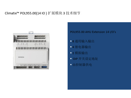
Climatix™ POL955.00(14 IO ) 扩展模块 3 技术细节
POL955.00 AHU Extension 14 I/O’s
8 通用输入输出
4 继电器输出 2 模拟输出 DIP 开关设定地址 由控制器供电
Climatix™ POL945.00(8 IO ) 扩展模块 4 技术细节
Climatix™ HMI 人机界面 HMI-DM POL895.50
技术细节
96×208点阵屏幕。 8行文字显示,可选白/蓝背光 便宜轻巧的旋钮操作键 带LED指示灯的报警按钮
可配置级别的用户操作权限
提供多种与控制器连接接口 (RS485、KNX) 支持多HMI链接,远程安装 从控制器供电 墙壁和控制柜内安装
技术细节
通过通讯总线连接到Climatix控 制器 M-Bus 模块提供连接具有M-Bus 接口的热表、能量表等。 最多可为6个M-bus设备提供电 源 可通过主控制器SD卡升级
Climatix™ 系列控制器平台为OEM提供全面的楼宇集成方案 ——开放的通讯协议提供全面的支持
在各个系统和渠道都要求控制器具有开放的标准通讯协议; 对于楼宇系统的工程设计和集成的高级要求可以满足 通讯协议的开发工具带来高附加值;“ HVAC系统能够和其他楼宇系统、设备协调工作
莱珂D202+D203+D208+D301+D302+B301+S301采暖温控+说明书
电源电压:AC220V, 50/60Hz 定时误差:<1% 负载:见接线图 精确度:±0.5℃ 温度设定范围:5℃-40℃ 自身功耗: <1W 感温元件:NTC 尺寸:86*86*37mm (L*W*D)三, 使用方法1.开、关机:通电状态下,请按开/关机键。
按住开、关机键4秒钟,屏幕出现图样,表示按键已被锁。
同样按住开/关机键4秒,图样消失,锁键取消。
2.工作模式:请按模式键,实现手动、编程、睡眠三种工作模式切换。
睡眠模式只测温度。
3.温度设定:请按加键和减键来调整。
4."5+2"制热编程模式(如无编程功能模式产品,则无以下功能):周一到周五共用相同的时段/温度设置,周六、周日用相同的时段/温度设置。
每天4个时段,温控器自动转换设置温度,从而智能的控制室内温度。
开机状态下,请按模式键切换至编程模式,再按键"设置键"4秒进入"5+2"制热编程模式。
当需要更改时段的"开始时间"和"设置温度"时:请切换至"5+2"制热编程模式后,然后方可进行如下操作:按住设置键4秒钟以上,界面进入编程模式设置,依次设置小时、分钟、设置注意:在按下设置键后,若在8秒钟内无操作返回主界面。
5.菜单模式:关机状态下按住模式键4秒以上松开,进入菜单设置模式。
然后每按一次模式键,屏幕出现1至6数字的转换,代表6个参数。
按加键、减键来改变参数值。
8秒不动作按键,自动跳回温控器原状态。
数字"1"--温度校正界面,按加键、减键调整校正值,9℃到-9℃可调,默认为0℃。
数值"2"--防冻功能选择界面,当图标"--"显现出来时表示防冻功能取消。
按加键、减键设置防冻温度;当防冻功能开启后,室温高于防冻温度2℃后温控器自动关闭;默认为取消防冻功能。
Sporlan电子阀门控制板说明说明书
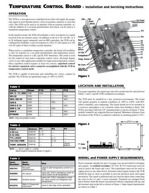
OPERATIONThe TCB is a microprocessor-controlled device that will supply the properstep signal to most Sporlan electric valves to position, initialize or close thevalve. The TCB can be used as an interface with an external controller; or,with the addition of a set point potentiometer and sensor, can be used as astandalone temperature control.In the interface mode, the TCB will modulate a valve in response to a signalreceived from an external source. In addition to the 0 to 10 volt DC, or 4to 20 milliamp signal commonly used on PID controllers, the TCB can beconfigured to modulate a valve in response to a TLL (5 volt) signal, or a 120volt AC pulse of three to thirty seconds duration.When used as a standalone temperature controller, the board will modulatea valve in response to a set point potentiometer and temperature sensor.The temperature sensor is a 2K, type B, NTC thermistor. This mode is usedfor the control of step motor evaporator control valves, discharge bypassvalves or any other application suitable for single point temperature control.Since superheat control requires at least two sensors, superheat controlfor electric expansion valves cannot be accomplished with the TCB intemperature control mode.The TCB is capable of powering and controlling two valves, connect inparallel. The TCB has an operational range of -40°F to 210°F.For proper operation, the signal type and valve model must be selected fromTables 1 and 2, and the TCB configured accordingly.The TCB must be installed in a dry, protected environment. The boardwill operate properly in ambient conditions of -40°F to 140°F, with 90%relative humidity, non-condensing. The board should never be mounted ina corrosive atmosphere or in a location where frost buildup is likely. TheTCB is provided with four 1/8” mounting holes as shown in Figure 2. Non-metallic standoffs are suggested but not required. Minimum clearance fromthe bottom of the TCB to a conductive substrate or mounting panel is 3/16”.WIRING and POWER SUPPLY REQUIREMENTSScrew terminals suitable for up to 14 gauge wire are provided for all inputsand outputs. An isolated secondary 24 VAC 40 VA transformer must beused to power the board and valve. The transformer must not be used tosupply power to any other device. External control signal wiring to the TCBshould be kept as short as possible to prevent electrical noise and signalattenuation. The signal is polarized and care must be taken when connectingthe wires to the (+) and (-) screw terminals. Terminals are arranged fromtop to bottom when the board is positioned with the component side up, andthe terminal strip on the left as shown in Figure 1. Input signal requirementsare shown in Table 3.T emperaTure C onTrol B oard - Installation and Servicing Instructions1” max.3/16” min.Figure 2NOTE: Only one jumper is used.NOTE: L = left, R = right, C = centerWhen board is viewed as shown in Figure 1.fdeREPLACEMENT PARTS AND PARTS KITSThere are no user serviceable parts on the TCB, however, the accessories listed in Table 3 aid in the use and testing of the TCB/electric valve system.TROUBLESHOOTINGIf a step motor is suspected to have failed, a simple resistance check may be made of the motor windings, however, actual winding failures are rare. Therefore Sporlan developed a diagnostic instrument, the SMA-12, to test our step motors. The SMA-12 is a step motor actuator that will operate all 12 volt DC bipolar step motor valves, as well as test the continuity of the valve wiring and motor. The step rate can be selected at 1, 50, 100 or 200 steps-per-second. At the one step-per-second rate the SMA-12 will test the continuity of the valve wiring and motor. The SMA-12 can also be used to manually open, position, or shut the valve should the controller fail. If contaminants are suspected, the SMA-12 can be used to drive the valve fully open to purge the foreign material.NOTE: Pin 8 causes valve to open on temperature rise above set point. Pin 9 causes valve to close on temperature rise above set point.4-20 MILLIAMP - source controller must supply 20 milliamps at 12volts DC into a 600 Ohm load.NOTE: 20 milliamps at 24 volt DC is not suitable. 0-10 VOLT - signal must be supplied with at least 20 milliampcurrent. Wiring between controller and TCB must be kept short to minimize electrical noise.TTL - logical “1” must be a DC signal greater than 4.5volts for 3 milliseconds. Logical “0” must be less than 0.5 volts DC for 3 milliseconds.AC PULSE - Must be 120 volts AC ± 20% for a period of 3 to30 seconds.INPUT SIGNAL REQUIREMENTS50000010000200003000040000-6010080604020-20-40120200180160140Temperature (Degrees Fahrenheit)O h m sFigure 3TEMPERATURE SENSOR RESISTANCEWhen a system component does fail, it is important to first determine whether the failure is the valve, the TCB, or the external controller (if used).TEST THE VALVEThe resistance of the motor winding may be tested without opening the system.1. Remove power from the external controller and/or TCB.2. Remove the valve leads from TCB.3. Measure the resistance between the black and white leads of the valve. The resistance should be 75 Ohms for brass housed valves with the valve at room temperature or about 65 Ohms if the valve is at -40ºF. The resis-tance for stainless steel housed valves should be 100 Ohms with the valve at room temperature.4. Measure the resistance between the green and red leads. This value should be within ± 5% of the resistance between the black and white leads.5. Measure the resistance from any lead to valve body. Resistance should be infinite, that is to say, open.TEST THE TCBThe flow charts that follow are designed to assist in diagnosing a possible TCB failure. All measurements should be made with a Digital Multimeter .Boards manufactured after March 1, 2000 will have a pin jumper on both P5 and P6. The boards are shipped with the jumpers on one post of P5 & P6. With the pin jumpers in this position, the valve will close when the pumpdown relay is energized. If both P5 & P6 are enabled, the valve will open when the pumpdown relay is energized.For testing purposes, make sure the pin jumpers are on both posts of pins P5 & P6.Look at the date on the serial number label in the center of the board. If the date is prior to March 1, 2000, continue with steps 9 through 13. If the date is March 1, 2000 or later, go to step 14 and continue.TROUBLE SHOOTING GUIDE – TCB Operating on External Signal (4-20 ma or 0-10 VDC)*Note: Before testing the TCB, make certain the valve is operating. See “Test the Valve” instructions.Boards manufactured after March 1, 2000 will have a pin jumper on both P5 and P6. The boards are shipped with the jumpers on one post of P5 & P6. With the pin jumpers in this position, the valve will close when the pumpdown relay is energized. If both P5 & P6 are enabled, the valve will open when the pumpdown relay is energized.For testing purposes, make sure the pin jumpers are on both posts of pins P5 & P6.Look at the date on the serial number label in the center of the board. If the date is prior to March 1, 2000, continue with steps 9 TROUBLE SHOOTING GUIDE – TCB Operating as Standalone ControllerNote: Before testing the TCB, make certain the valve is operating. See “Test the Valve” instructions.。
H12012温度 过程控制器用户指南说明书

'DWD $FTXLVLWLRQ
Communication Products and Converters, Data Acquisition and Analysis Software, Data Loggers Plug-in Cards, Signal Conditioners, USB, RS232, RS485, Ehernet and Parallel Port Data Acquisition Systems, Wireless Transmitters and Receivers
$8 Noise suppression kit, 110 to 230 Vac
* Requires external 250 Ω precision shunt resistor, OMX-R250 (sold separately).
MOST POPULAR MODELS HIGHLIGHTED!
Comes complete with operator’s manual. Ordering Examples: CN7223, dual output controller, DC pulse, mechanical relay output, RS485 communications, $169.
Thermocouple Type
100 to 1800°C (212 to 3272°F)
alarm outputs. The second relay output can be reconfigured as a third alarm output. The alarm type
Thermocouple Type
ߜ RS485 Communications ߜ Free Software
WJ(M-PRO)系列控制器使用说明书
-Uppf功率因数控制器使用说明书-
安装本自动功率因数调整器时,请务必遵守标准作业规范和安全准则。 安装: 1. 确认量测与控制电压、供电频率和电流转换比是否与控制器技术资料吻合。 2. 配电盘上开孔尺寸是 138*138mm.,利用两个固定夹将此调整器安装至配电盘上,其
嵌入的深度是 49mm。
3. 根据配线图进行接线。
4. 请连接保护接地于设备金属外壳上的 PE 接点。
5. 请移除 CT 短接片。
-2-
1、产品概述
Uppf 功率因数控制器使用说明书
Uppf 功率因数控制器是集数据采集、无功补偿、电网参数分析等功能于一体的新型配
电测控设备,适用于交流 0.4KV、50Hz 低压配电系统的监测及无功补偿控制。
Uppf 功率因数控制器以高速数字信号处理器为核心,采用交流取样,人机界面为 128X64
6.3 参数设置 ............................................................. 7
6.4 超限及故障警示 ...................................................... 14
7、安装与测试............................................................... 15
4.1 实时数据监测 ......................................................... 3
4.2 无功补偿 ............................................................. 4
5、技术数据.................................................................. 4
pol系列暖通控制器综合说明
s3900Climatix TMClimatix 产品系列POL68X.XX/XXX,POL63X.00/XXX,POL985.00/XXX, POL965.00/XXXPOL955.00/XXXPOL94U.00/XXX, POL94E.00/XXXPOL945.00/XXX, POL925.00/XXXPOL902.00/XXXPOL904.00/XXX, POL906.00/XXXPOL907.00/XXX, POL908.00/XXXPOL909.00/XXXClimatix 系列是为暖通空调、制冷和区域供热领域设计的专业控制产品。
强大的工程和服务工具平台为暖通空调、制冷应用提供全面的支持,易于开发调试。
CB1Q3900zh_012 / 16POL68X 通讯概念POL63X 通讯概念3 / 16Climatix 6XX 产品系列专为暖通空调、制冷、区域供热领域而设计,并为该领域的应用提供了广泛的控制监视功能。
该产品系列属于模块化设计,包含不同版本的主控制器(内置 HMI 或不带内置 HMI )、不同型号的 I/O 扩展模块、可驱动步进电机的扩展模块,以及可工厂或现场安装的增强通讯模块。
不同类型可供选择的人机界面 HMI ,可本地或者远程连接控制器实现操作监视功能。
该系列控制器可自由编程。
可通过功能强大且界面友好的 SAPRO 编程工具对 Climatix 控制器进行自由编程,从而在暖通空调、制冷应用程序开发与测试过程中节省大量时间与投入。
此外免费提供的一款强大调试软件 SCOPE ,对于应用的开发提供全面的帮助。
可配置的输入/输出通道,为一个主应用程序适应不同的特定需求提供了可能性。
实际上,模块化的设计可以扩展主控制器的 IO 容量,能够更加灵活地适应应用程序的配置,且连接方式可为本地或者远程。
模块化设计的 IO 扩展针对暖通空调、制冷领域的实际应用进行了最佳优化。
主控制器板载的通讯接口可提供基本的通讯功能,完善了系统的升级扩展性和智能化。
海洛斯操作手册说明书
HIROSS恒温恒湿机房精密空调操作手册HIMOD系列北京****科技有限公司技术部2009年01月01日目录第一章HIMOD系列海洛斯空调概述....................................................................................1.1型号多 ....................................................................................................................................1.2控制技术先进 ........................................................................................................................1.3制冷系统 ................................................................................................................................1.4送风系统 ................................................................................................................................1.5加湿系统 ................................................................................................................................1.6加热系统 ................................................................................................................................1.7其它 ........................................................................................................................................ 第二章HIMOD系列海洛斯空调型号含义............................................................................ 第三章有关空调的一些资料 ..................................................................................................3.1气流组织方式 ........................................................................................................................3.2盖板纽开启方式 ....................................................................................................................3.3空调重量 ............................................................................................................................3.4机组尺寸及维护空间 ............................................................................................................ 第四章制冷循环管路示意图 ..................................................................................................4.1风冷却(A型).....................................................................................................................4.2水冷却(W型)....................................................................................................................4.3双冷源(D型).....................................................................................................................4.4单系统(C型).....................................................................................................................4.5双系统(C型)..................................................................................................................... 第五章调速风机调速接线示意图........................................................................................... 第六章MICROFACE概述......................................................................................................6.1概述 ........................................................................................................................................6.2Microface面板简介................................................................................................................6.3LCD液晶显示屏介绍 ............................................................................................................ 第七章MICROFACE面板的操作.......................................................................................... 第八章控制器的使用 ..............................................................................................................8.1控制器(HIROMATIC)概述 ..............................................................................................8.2控制器的操作 ........................................................................................................................8.3菜单结构 ................................................................................................................................ 第九章日常维护及特殊维护 ..................................................................................................9.1日常维护 ................................................................................................................................9.2特殊维护 ................................................................................................................................ 第十章常见报警及处理 ................................................................................................................10.1低压报警 ..............................................................................................................................10.2高压报警 ..............................................................................................................................10.3加湿报警 ..............................................................................................................................10.4失风报警 ..............................................................................................................................10.5电加热过热报警 ..................................................................................................................10.6显示器发黑 ..........................................................................................................................10.7空调不制冷 ..........................................................................................................................附录1:参数列表 ....................................................................................................................附录2:报警内容列表 .............................................................................................................附录3:各菜单项含义 .............................................................................................................第一章HIMOD系列海洛斯空调概述HIMOD系列海洛斯空调(HIMOD空调)是当今世界上最先进的机房专用恒温恒湿机房专用精密空调。
Pro1 Technologies 制冷系统温度控制器说明书
FAN ON AUTO EmHCOOL OFF HEATSet AtLEAVEAMHold/RunTimeProgramPro1 TechnologiesToll Free: 888-776-1427 Web: Hours of Operation: M-F 9AM - 6PM EasternBattery PowerHardwire (Common Wire)Hardwire (Common Wire) with Battery BackupA trained, experienced technician must install this product.Carefully read theseinstructions. You could damage this product or cause ahazardous condition if you fail to follow these instructions.Una version en español de este manual se puede descargar en la pagina web de la compañia.Rev. 1823U.S. Registered Trademark. Patents pending Copyright 2018 All Rights Reserved.Installation TipsThermostat Quick Reference WiringWiring DiagramsFeatures & About The BadgeTechnician Setup Programming Thermostat 4-56 7813-16Subbase Installation The thermostat should be installed approximately 4 to 5 feet above the floor. Select an area with average temperature and good air circulation.• Close to hot or cold air ducts • That are in direct sunlight • With an outside wall behind the thermostat• In areas that do not require conditioning• Where there are dead spots or drafts(in corners or behind doors)• Where there might be concealed chimneys or pipesWall LocationsVertical MountHorizontal MountFor vertical mount put one screw on the top and one screw on the bottom.For horizontal mount put one screw on the left and one screw on the right.Do not installthermostat in locations:Mount ThermostatAlign the 4 tabs on the subbase with corresponding slots on the back of the thermostat, then push gently until the thermostat snaps in place.Battery InstallationBattery installation is recommended even if thermostat is hardwired (C terminal connected). When thermostat is hardwired and batteries are installed, the thermostat will activate a compressor delay of 5 minutes when the thermostat detects a power outage from the hardwired power supply.Important:High quality alkaline batteries are recommended. Rechargeable batteries or low quality batteries do not guarantee a 1-year life span.Insert 2 AAquality alkaline batteries are recommended.Simple operating instructions are found on the back of the battery door.Getting to know your thermostatSystem SwitchEasy change battery door Temperature Setpoint Buttons LCD DisplayThermostat Quick ReferenceSpecificationsThe display range of temperature ... 41˚F to 95˚F (5˚C to 35˚C)The control range of temperature.... 44˚F to 90˚F (7˚C to 32˚C)Swing (cycle rate or differential) ...... Heating is adjustable from 0.2˚ to 2.0˚ Cooling is adjustable from 0.2˚ to 2.0˚Power source ...........................................18 to 30 VAC, NEC Class II, 50/60 Hz for hardwireBattery power from 2 AA Alkaline batteriesOperating ambient ............................... 32˚F to +105˚F (0˚C to +41˚C)Operating humidity .............................. 90% non-condensing maximum Dimensions of thermostat ................. 4.7”W x 4.4”H x 0.8”D9 -12P .O. Box 3377Springfield, MO 65808-3377Fan Switch User ButtonsT625-2Tech SettingsTech SettingsSwing Setting TipTemperature swing, sometimes called differential or cycle rate, can be customized for this individual application. For most applications choose a swing setting that is as long as possible without making the occupants uncomfortable.LCD Will Show temperature display to read 4˚above or below the factory Tech Settings Adjustment OptionsDefaultTech SettingsAdjustment OptionsDefaultadjustable from 0.2˚ to 2˚. For example: A swing setting of Use the and key to Use the and key to LCD Will Show This thermostat has a technician setup menu for easy installerconfiguration. To setup the thermostat for your particular application:Swing Setting TipTemperature swing, sometimes called differential or cycle rate, can be customized for this individual application. For most applications choose a swing setting that is as long as possible without making the occupants uncomfortable.Technician Setup Menuhomeowners do not accidentally access the installer settings.3. Press the Program button to advance to the next step. 4. Press the time button to go back to the previous stop.5. Press the Hold/Run button to exit.The Technician Setup MenuTech Settings2H/1C Heat Pump System - Factory Default SettingTypical 2H/1C Heat Pump System with separate emergency heatCConventional System 1H/1C, 2H/1C (Heat pump set to “OFF” in tech settings)Note: Thisthermostat is only compatible with ONE transformer systems.(HOT)setpoint temporarily until next time period.Permanent Hold : If you press the HOLD button on the left of your screen, you will see HOLD appear to the right of the ambient To Return to Running Schedule : Press the RUN button on the left of your screen to exit either temporary or permanent hold.Gently slide a screwdriver into the bottom edge of the badge. Gently turn the screwdriver counter clockwise. The badge is held on by a magnet in the well of the battery door. The badge should pry off easily. DO NOT USE FORCE.About The BadgeAll of our thermostats use the same universal magnetic badge. Visit the company website to learn more about our free private label program.Magnet in doorUse the bevel on lower ridgeTech SettingsConventional & Heat PumpThe switch converts the thermostat between conventional and heat pump operation.Heat Pump : Configures the thermostat for heat pump operations.Conventional : Configures the thermostat for conventional operations.Use the or key to Tech SettingsAdjustment OptionsDefault LCD Will ShowUse the and key toProgrammingProgrammingSet Program Schedule1. Select HEAT or COOL with the system switch. Note: You have to program heat and cool each seperately.2. Press PROGRAM3. Monday-Friday is displayed and WAKE is shown. You are now programming the wake time period for the weekday setting.4.5. Press PROGRAM6.7. Press PROGRAM8. Repeat steps 4 thru 7 for weekday LEAVE time period, for weekday RETURN time period, and for weekday SLEEP time period.To customize your program schedule, follow these steps Weekday:Repeat steps 4 thru 7 for the Saturday WAKE time period, LEAVE time period, RETURN time period, and for the Saturday SLEEP time period.Saturday:Repeat steps 4 thru 7 for the Sunday WAKE time period, LEAVE time period, RETURN time period, and for the Sunday SLEEP time period.Sunday:You can use the table below to plan your customized program schedule.。
- 1、下载文档前请自行甄别文档内容的完整性,平台不提供额外的编辑、内容补充、找答案等附加服务。
- 2、"仅部分预览"的文档,不可在线预览部分如存在完整性等问题,可反馈申请退款(可完整预览的文档不适用该条件!)。
- 3、如文档侵犯您的权益,请联系客服反馈,我们会尽快为您处理(人工客服工作时间:9:00-18:30)。
s3900Climatix TMClimatix 产品系列POL68X.XX/XXX,POL63X.00/XXX,POL985.00/XXX, POL965.00/XXXPOL955.00/XXXPOL94U.00/XXX, POL94E.00/XXXPOL945.00/XXX, POL925.00/XXXPOL902.00/XXXPOL904.00/XXX, POL906.00/XXXPOL907.00/XXX, POL908.00/XXXPOL909.00/XXXClimatix 系列是为暖通空调、制冷和区域供热领域设计的专业控制产品。
强大的工程和服务工具平台为暖通空调、制冷应用提供全面的支持,易于开发调试。
CB1Q3900zh_012 / 16POL68X 通讯概念POL63X 通讯概念3 / 16Climatix 6XX 产品系列专为暖通空调、制冷、区域供热领域而设计,并为该领域的应用提供了广泛的控制监视功能。
该产品系列属于模块化设计,包含不同版本的主控制器(内置 HMI 或不带内置 HMI )、不同型号的 I/O 扩展模块、可驱动步进电机的扩展模块,以及可工厂或现场安装的增强通讯模块。
不同类型可供选择的人机界面 HMI ,可本地或者远程连接控制器实现操作监视功能。
该系列控制器可自由编程。
可通过功能强大且界面友好的 SAPRO 编程工具对 Climatix 控制器进行自由编程,从而在暖通空调、制冷应用程序开发与测试过程中节省大量时间与投入。
此外免费提供的一款强大调试软件 SCOPE ,对于应用的开发提供全面的帮助。
可配置的输入/输出通道,为一个主应用程序适应不同的特定需求提供了可能性。
实际上,模块化的设计可以扩展主控制器的 IO 容量,能够更加灵活地适应应用程序的配置,且连接方式可为本地或者远程。
模块化设计的 IO 扩展针对暖通空调、制冷领域的实际应用进行了最佳优化。
主控制器板载的通讯接口可提供基本的通讯功能,完善了系统的升级扩展性和智能化。
增强的扩展通讯模块为楼宇系统的需要提供了各类接口。
主控制器可以选择是否由人机界面 HMI 来进行操作和监视,但其控制功能相同;Climatix 控制器系列提供内置 HMI 和外接 HMI (通常为面板安装)。
此外,外接 HMI 可通过过程总线远程接入,该过程总线基于 KNX 技术,可通过双绞线为 HMI 提供电源,由此节约了安装成本。
扩展 IO 模块通过设备总线与主控制器连接,包含有不同的型号,其 IO 通道均可配置。
步进电机控制模块是一个特殊的 IO 扩展模块,用来为电子膨胀阀提供驱动。
模块化的 IO 模块设计,简化了按照功能需求进行主控器和 IO 模块的配置,即可根据功能需求配置不同的 IO 模块,为控制系统设计和应用程序的开发提供了便利。
硬件配置的灵活对于模块化设计控制电柜也有极大的益处,在控制柜的机械设计匹配概念、通讯和电源的配置等方面都会得到体现。
增强的通讯模块(BACnet/IP 、BACnet/MSTP 、LON 、MBus 、Modbus RS-485 以及 AWM 高级可编程 Web 模块)扩展了 Climatix 控制器的通讯连接选项,实现了楼宇系统的无缝集成,而且可以提供可定制的远程高级服务功能。
Climatix 600 系列概览主控制器人机界面 HMII/O 扩展模块系列增强通讯模块Climatix 6XX –产品系列4 / 165 / 16Climatix 产品系列POL687.00/(请参阅技术文档 Q3903)POL687.70/内置 HMI (请参阅技术文档 Q3903)POL635.00/(请参阅技术文档 Q3230)POL636.00/(请参阅技术文档 Q3230)POL638.70/内置 HMI (请参阅技术文档 Q3230)POL985.00/(请参阅技术文档 Q3221)POL965.00/(请参阅技术文档 Q3222)POL955.00 (请参阅技术文档 Q3226)POL94U.00/(请参阅技术文档 Q3225)POL94E.00/(请参阅技术文档 Q3225)POL945.00/(请参阅技术文档 Q3223)POL925.00/(请参阅技术文档 Q3224)POL895.5x/ HMI(请参阅技术文档 N3941)POL902.00/ Modbus RS485 (请参阅技术文档 Q3234)POL904.00/BACnet MSTP (请参阅技术文档 Q3232)POL906.00/ LON(请参阅技术文档Q3231)POL907.00/ M-Bus(请参阅技术文档 Q3236)POL908.00/ BACnet IP(请参阅技术文档Q3233)POL909.00/ AWM Web (请参阅技术文档Q3235)主控制器和 HMIIO 扩展模块人机界面 HMI增强通讯模块6 / 16SAPRO 编程工具 (ACX93.00)SCOPE 调试工具模块连接组件增强通讯模块板-板 连接器主控制器板-板 连接器IO 扩展模块配置示例增强通讯模块 主控制器IO 扩展模块(985、965、955、94U 、94E 、945、925)软件工具7 / 16附件订购号板-板固定式连接器Phoenix ZEC1,0/4-LPV-3,5 GY35AUC2CI1 板-线直接插拔式连接器PhoenixZEC1,0/4-ST-3,5 GY35AUC1R1,4通讯模块总线连接板-板固定式连接器PhoenixZEC1,0/10-LPV-3,5 GY35AUC2CI1控制器附件实时时钟电池 BR2032 POL 0B1.20/STD 编程电缆 80 cm POL 0C2.20/STD 编程电缆 150 cm POL 0C2.40/STD SAPRO 编程软件 ACX93.000工程测试箱 POL 0G6.87/STD连接端子(笼型弹簧连接,电缆上入)POL 068.76/STD 1 x Phoenix FKCT 2,5/2-ST OG1 x Phoenix FKCT 2,5/2-ST GY7035 6 x Phoenix FKCT 2,5/3-ST KMGY 1 x Phoenix FKCT 2,5/5-ST GY7035 1 x Phoenix FKCT 2,5/6-ST GY7035 1 x Phoenix FKCT 2,5/7-ST GY70352 x Phoenix FKCT 2,5/8-ST GY7035连接端子(笼型弹簧连接,电缆侧入)根据需求选配 1 x Phoenix FKCVW 2,5/2-ST OG1 x Phoenix FKCVW 2,5/2-ST GY7035 6 x Phoenix FKCVW 2,5/3-ST GY7035 1 x Phoenix FKCVW 2,5/5-ST GY7035 1 x Phoenix FKCVW 2,5/6-ST GY7035 1 x Phoenix FKCVW 2,5/7-ST GY70352 x Phoenix FKCVW 2,5/8-ST GY7035连接端子(螺钉连接,电缆侧入)根据需求选配 1 x Phoenix MVSTBW 2,5/2-ST OG1 x Phoenix MVSTBW 2,5/2-ST GY7035 6 x Phoenix MVSTBW 2,5/3-ST GY7035 1 x Phoenix MVSTBW 2,5/5-ST GY7035 1 x Phoenix MVSTBW 2,5/6-ST GY7035 1 x Phoenix MVSTBW 2,5/7-ST GY70352 x Phoenix MVSTBW 2,5/8-ST GY7035设备总线连接连接扩展模块布线与接地规则关于供电和设备总线(连接 IO 扩展)的技术要求:•若连接扩展模块的设备总线长度超过 3 m,必须选用屏蔽电缆(L1 + L2 + Lx ≥3 m)•若连接扩展模块的设备总线小于 3 m,对于是否使用屏蔽电缆无要求(L1 + L2 + Lx ≤3 m)•屏蔽层必须只在一端接地•设备总线最长不能超过30 m (L1 + L2 + Lx ≤30 m)•使用直接插拔式连接器连接总线电缆和模块•供电电源的GND 必须可靠接地(参照上图)•远程连接位于不同处所控制设备的扩展模块,可使用 2 线制的总线 (A+ 和 B-)。
这种情况下, 连接的模块必须使用另外的电源供电(参照上图)。
必须保证所有的电源共用一个参照地•根据通过电流限制和模块功耗原则,来限制通过每一个单独模块的电流和功耗8 / 169 / 16IO 扩展模块的地址配置 扩展模块上配有 DIP 开关,用来设置与主控制器通讯时的地址。
DIP 开关 1、2、3、4、5 用来设置 IO 模块的从站地址,DIP 的第 6 位用来设置设备总线的终端电阻。
当扩展模块在整个网络的最终端时,开关 6 必须设置为“ON ”(终端电阻打开)。
通过 DIP 开关 1、2、3、4 或 5 的组合(二十进制 BCD 码),最多可配置 31 个从站地址。
下面是一些配置示例:扩展模块 DIP 开关设置 从站地址 (扩展模块)开关 1开关 2开关 3开关 4开关 5图例1Off Off Off Off On2 Off Off Off On Off3 Off Off Off On On4 Off Off On Off Off--- --- --- --- --- --- ---30 On On On On Off31 On On On On On扩展模块上 DIP 开关设置的地址必须和应用程序 (Sapro) 配置的 IO 模块的地址相同。
从站地址不能设置为 0。
DIP 开关注意F扩展模块连接通过电流限制原则通过电流是通过每一个模块的最大电流,限制的原则是保持该电流在安全级别。
当扩展模块和主控制器一组,或只有扩展模块为一组,通过设备总线供电时,必须计算以确保这一组总的电流功耗不超过 96 VA。
如果实际连接的控制器和扩展模块的总电流功耗超出限制,可采用分组的方法来确保每一组的电流功耗不超过 96 VA。
注意:使用交流 AC 24 V供电,电流功耗比使用直流 DC 24 V 稍高,因为直流电源的有功功率较高。
所以,当采用直流电源供电,使用同一电源连接为一组的模块数量要比采用交流电源时多。
最大模块连接数量31 (1…31)每组最大通过电流(最大功耗)96 VA连接电缆长度Max.30 m以下是不同分组模块连接的例子:下面表格提供了按每个单独模块的全负荷配置时,控制器的最大功耗。
实际使用时,功耗可能会依照实际情况略小。