海德堡主电机控制说明
海德堡
第三层LTE是电源部件插座单元。电压板LTK500是带酒精润版系统的印刷机用来控制4个印刷机组水斗电机用的。图10中的LTK50电路板是控制水斗转动的。纸堆控制板STK1负责向飞达和收纸部分的主纸堆提供电源。
ห้องสมุดไป่ตู้第四层是SSE伺服驱动插座单元。电源板NTK24向伺服装置提供电源。SSK是伺服驱动控制板,用于控制吸气头的高度调节、歪张校正、拉规调节等伺服电机。电压板LTK500负责向伺服电机提供电压。BAK是制动器控制电路板。
图6所示为收纸MID显示器的特殊功能显示图。它可显示水斗辊速度和纸张制动速度。图中①为有关位置代码,②为速度图形显示,③为速度百分比。
3.控制程序图
(1)在控制台操作印刷机时按图7所示流程进行
①进行指令选择,如预置、换活儿、分色、清洗;
②状态显示,如选择实际值显示,则功能控制立即直接影响印刷机;如选择预置显示,则功能控制存储在控制台,并在操作、走纸或印刷中自动改善印刷机组;
③在整机、收纸、印刷单元及飞达中进行单元选择;
④组/印刷单元选择,如走纸、吸气印刷机组等;
⑤功能选择,如启/停走纸、润版等,然后可进行调整,如调节水斗辊速度、吸气辊速度、工作计数器和预置等;
(2)控制台操作按图8所示流程进行
①启动印刷机后,控制台上3个故障信号灯哪个闪亮则对应哪个部位出现故障;
②选择故障显示方式;
海德堡印刷设备说明书
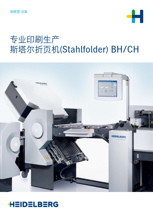
海德堡·设备专业印刷生产斯塔尔折页机(Stahlfolder)BH/CH海德堡——为您带来丰厚回报的合作伙伴印刷企业获得成功的关键在于人员、流程、材料和设备之间是否能实现完美的无缝式衔接配合。
长期以来,海德堡一直是印刷企业最值得信赖的合作伙伴,为满足您——我们的客户提出的所有印刷需求,海德堡不断潜心研究,推出了方便用户操作的系统,可定制化的产品和创新型的服务,以便您能享受到最高的生产质量,更轻松快捷地控制复杂的印刷流程,并能及时纠错,帮助您更好地优化整个生产流程,而这一系列最终将化为一个结果,那即是:您只需点击一键即可轻松实现高效生产。
我们称其为“Simply Smart”,它将为您带来:可根据您的需求量身定制的智能而全面集成的产品组合,帮助您打造更简单而高效的生产流程。
h e id e lb e /cn/company05斯塔尔折页机(Stahlfolder) BH/CH 06自动化0815大显著优势10内部视图14直角折页单元16收纸装置18应用我们将为您提供:设备面向未来——通过把数码印刷和胶印技术相结合来优化印刷生产工艺。
海德堡的印刷设备产品线既包含最尖端的数码科技、极具竞争力的标准化设备,还囊括各种为生产力最大化以及所有可能的印刷应用所需的个性化特别配置的设备。
从印前、印刷直至印后——海德堡能够为商务印刷和包装印刷提供整个生产流程。
通过印通,所有海德堡设备得以顺畅连接配合并生成相应的生产数据:这对流程优化和透明化管理都非常重要。
您的质量标准不容妥协! /cn/equipment服务海德堡全方位的服务平台,为您提供了更多时间关注核心业务。
海德堡专业的技术专家团队及高品质的原装零配件为您的稳定、高效生产保驾护航。
在通往优化及完善各领域高效生产的道路上,海德堡与您并肩同行。
海德堡毋庸置疑是您最值得信赖的合作伙伴。
/cn/service 材料海德堡优质的印刷材料搭配专业的技术使用手册,助您达到最佳的印刷效果。
海德堡四色机作业指引
5.5润版液调节:根据版面图文裁墨量的支配量调节润版液供给量的大小,使水墨趋于平衡。
5.6按三级签样进行首检,OK后批量生产。批量生产时机长每200张对印刷质量自检一次、二手每30分钟搅拌墨斗一次,检查水斗一次。
200g哑粉
0.19mm
±0.02mm
0.17-0.2
250g哑粉
0.27mm
±0.02mm
0.25-0.29
300g哑粉、270g灰咭
0.35mm
±0.02mm
0.33-0.37
250g单粉咭
0.3mm
±0.02mm
0.28-0.32
300g单粉咭、300g灰咭
0.38mm
±0.02mm
0.36-0.40
作业指引
生效日期
修订记录
批准
审核
制作
事业处/部门
一处/印刷部
2010/12/31
NO
日期
记录
文件名称
CD102-4海德堡四色机作业指引
版本
1
04.09.10
整合ISO9001-2000、ISO14001-1996和OHSAS18000三体系。
2
05.03.04
1.3内容变更及2.0中增加2.7项内容。
5.0作业内容
5.1换色:把输墨系统原落版墨色洗净,换下一次印色要求的油墨;换色要求墨辘要洗净,不能留残墨,墨斗不能有挂墨现象。
5.2上版:把准备好的PS版用版夹和螺丝按规定的位置固定在印版滚筒上,要求印刷上机歪斜不能过大。
5.3校正规矩:开动印刷机,将速度调至8000-9000转/小时,根据套印十字印矩线校版,要求速度快,避免印版串动过频,引起牙口边和拖稍边受损裂。
海德堡印刷机控制系统及模拟操作系统(可编辑)
海德堡印刷机控制系统及模拟操作系统(可编辑)项目十印刷机控制系统及模拟操作系统模块一控制系统现在最典型的有罗兰CCI(Compuer Controlled InkingSystem)系统、海德堡的CPC(Computer Printing Control System)系统、小森PQC(Ptinting Quality and Control)系统、高宝Colortronic系统等。
海德堡印刷机械股份公司研制的CPC Computer Print Control 计算机印刷控制系统是一种可扩展式系统,由给墨量和套准遥控装置CPC1、印刷质量控制装置CPC2、印版图像测读装置CPC3、套准控制装置CPC4和CP Tronic(CP 窗)自动监测和控制系统组成。
如图3-97所示。
(1)CPC1-01 为基本控制装置,它通过按钮遥控给墨和套准,包括区域墨量、墨斗辊墨条宽度遥控装置及轴向、周向套准装置。
为了便于控制,该供墨装置沿墨斗轴向安装了32个计量墨斗辊,把给墨区域分成32个小区域,每个计量辊的宽度为32.5mm,计量墨辊中间大部分做成偏心柱。
通过微电机转动计量墨辊,以改变计量墨辊和墨斗辊的间隙,便可调节该区域的墨量。
控制台上设有控制微电机的32个间隙调节按键7,按键上方设有32套显示装置8,每套显示其由16个发光二极管组成,用于显示墨斗辊与计量辊之间的间隙,其间隙的调节范围在0―0.52mm之间,每小格表示0.1mm 间隙。
整个墨斗出墨量的粗调是通过按键5,改变墨斗辊间歇回转角的大小来实现的。
墨斗辊回转角的大小通过微电机控制,同时由轴端电位计将调整信号用数字显示出来。
所显示的数字为最大回转角的百分数,调节精度为最大回转角的1%。
图中按键3、4是遥控印版滚筒轴向和周向套准,并通过控制印版滚筒轴端的电机来实现。
调节精度为0.01mm,调节范围为+/-2mm。
(2)CPC1-02控制装置采用光笔和按钮进行墨量的整体快书和局部遥控调节,有存储记忆功能。
海德堡印刷机操作手册
xxxxxxxxxxxxxxx股份有限公司印刷车间海德堡四开五色平版印刷机操作指导书文件编号:文件版本:发放号码:受控状态:生效日期:编制:审核:批准:目录一、目的二、适用范围三、应作文件四、生产设备五、胶印简单流程图六、技术参数七、劳动安全及生产要求八、设备操作与保养1、目的本操作指导书为设备操作人员操作海德堡四开五色平版印刷机进行相关的质量检验提供工作指导。
2、适用范围本操作指导书适用于xxxxxxxxxxxxx股份有限公司海德堡四开五色平版印刷机,胶印设备。
3、应用的文件《海德堡四开五色平版印刷机使用说明书》4、生产设备德国海德堡机械有限公司所生产四开五色平版印刷机介质电压:380V 额定电流:30A频率:50HZ 气压:≥6kg/c㎡温度: 18ºC—25ºC; 相对温度:45%—65%、胶印简单生产流程图56.1印刷材料:最大纸张尺寸:600*740mm (尺寸F)530*740mm(尺寸C) 最小纸张尺寸:210*350mm 最大纸张厚度:0.8mm 6.2油墨/上光:6.2.1 只能够使用单张纸胶印机专用印刷油墨和上光材料。
6.2.2 上光装置中只允许使用水基分散上光液,在使用紫外线上光液时,则需要使用专手型印刷机型。
6.3 自动清洗装置使用清洗液只允许使用具有下列特性的清洗液:闪点至少达到55℃。
苯含量要低于0.1%二甲苯和混合二甲苯的仿量小于1%芳香烃物质含量(>Cg)小于1%清洗剂中不得带有氯化烃,氯化氟代烃,共同点烯,h-已烷,二胺和酰胺。
6.4 清洗剂和溶剂:要使用其闪点至少不55℃的清洗剂和溶剂。
6.5 噪声释放量:输纸机的噪声等线为84 dB(A)输纸机控制台处的噪声等级为:82dB(A)高纸堆收纸机上的噪声等级为:83 dB(A)6.6纸堆的最大重量:输纸机重量:1000kg收纸机重量:1000kg7、劳动安全要求应遵守公司内部的劳动安全条例。
注意:所有设备操作人员必须经过培训。
印刷机重要操作(海德堡)

•
應使用相同厚度與紙面特性的過版紙
海德堡印刷媒體技術中心
• • • • • • • • • • • • • • • • 12 • • • • • • • • • • • • • • • • •
瞭解裝版與定位技巧 ……
•
版夾頭歸零與校正
• • • • • • • • • • • • • • • • 13 海德堡印刷媒體技術中心 • • • • • • • • • • • • • • • • • 緊版的技巧與一次套准 ……
飛達導紙輪之設定 ……
•
• • • • • • • • • • • • • • • • 17 • • • • • • • • • • • • • • • • •
3號螺絲用來調整導紙 輪抬起與放下之時間, 兩個導輪必須調整同時 接觸下方之皮帶輥
•
當導紙輪完全接觸下方 皮帶輪後, 位置4螺絲與 底板間應有0.3mm間隙
• • • • • • •
印刷機重要操作
Clark Chung
海德堡印刷媒體技術中心
正確的墨輥安裝與設定………
• • • • •
• • • • • • • • • • • • • • • • 2 • • • • • • • • • • • • • • • • •
墨滾間正確壓力調整
墨滾直徑檢查
墨滾表面不能發亮 使用墨痕寬度標準卡 不同印刷機有不同的壓 力設定
不背印, 少噴粉 • 偏色少 M C Y Bk 疊印取代量
Dec_2005
• • • • • • • • • • • • • • • • • • • • • • • • • • • • • • • • • • • • • • • • 印刷業明天的效率與質量 • • • • • • • • • • • • • • •
海德堡印刷机操作手册
xxxxxxxxxxxxxxx股份有限公司印刷车间海德堡四开五色平版印刷机操作指导书文件编号:文件版本:发放号码:受控状态:生效日期:编制:审核:批准:修订记录版次修订内容编制/日期审核/日期批准/日期A 初版发布B目录一、目的二、适用范围三、应作文件四、生产设备五、胶印简单流程图六、技术参数七、劳动安全及生产要求八、设备操作与保养1、目的本操作指导书为设备操作人员操作海德堡四开五色平版印刷机进行相关的质量检验提供工作指导。
2、 适用范围本操作指导书适用于xxxxxxxxxxxxx 股份有限公司海德堡四开五色平版印刷机,胶印设备。
3、 应用的文件《海德堡四开五色平版印刷机使用说明书》4、 生产设备德国海德堡机械有限公司所生产四开五色平版印刷机 介质电压:380V 额定电流:30A 频率:50HZ 气压:≥6kg/c ㎡ 温度: 18ºC —25ºC; 相对温度:45%—65%5、 胶印简单生产流程图6、 技术参数原材料丝印胶印大张检验印刷材料:最大纸张尺寸:600*740mm (尺寸F)530*740mm(尺寸C) 最小纸张尺寸:210*350mm 最大纸张厚度:油墨/上光:6.2.1 只能够使用单张纸胶印机专用印刷油墨和上光材料。
6.2.2 上光装置中只允许使用水基分散上光液,在使用紫外线上光液时,则需要使用专手型印刷机型。
自动清洗装置使用清洗液只允许使用具有下列特性的清洗液:闪点至少达到55℃。
苯含量要低于%二甲苯和混合二甲苯的仿量小于1%芳香烃物质含量(>Cg)小于1%清洗剂中不得带有氯化烃,氯化氟代烃,共同点烯,h-已烷,二胺和酰胺。
清洗剂和溶剂:要使用其闪点至少不55℃的清洗剂和溶剂。
噪声释放量:输纸机的噪声等线为84 dB(A)输纸机控制台处的噪声等级为:82dB(A)高纸堆收纸机上的噪声等级为:83 dB(A)纸堆的最大重量:输纸机重量:1000kg收纸机重量:1000kg7、劳动安全要求应遵守公司内部的劳动安全条例。
海德堡印刷机操作手册
xxxxxxxxxxxxxxx股份有限公司印刷车间海德堡四开五色平版印刷机操作指导书文件编号:文件版本:发放号码:受控状态:生效日期:编制:审核:批准:一、目的二、适用范围三、应作文件四、生产设备五、胶印简单流程图六、技术参数七、劳动安全及生产要求八、设备操作与保养1、目的本操作指导书为设备操作人员操作海德堡四开五色平版印刷机进行相关的质量检验提供工作指导。
2、适用范围本操作指导书适用于xxxxxxxxxxxxx股份有限公司海德堡四开五色平版印刷机,胶印设备。
3、应用的文件《海德堡四开五色平版印刷机使用说明书》4、生产设备德国海德堡机械有限公司所生产四开五色平版印刷机介质电压:380V 额定电流:30A频率:50HZ 气压:≥6kg/c㎡温度: 18oC—25oC; 相对温度:45%—65%5、胶印简单生产流程图6、技术参数印刷材料:最大纸张尺寸:600*740mm (尺寸F)530*740mm(尺寸C) 最小纸张尺寸:210*350mm 最大纸张厚度:油墨/上光:6.2.1 只能够使用单张纸胶印机专用印刷油墨和上光材料。
6.2.2 上光装置中只允许使用水基分散上光液,在使用紫外线上光液时,则需要使用专手型印刷机型。
自动清洗装置使用清洗液只允许使用具有下列特性的清洗液:闪点至少达到55℃。
苯含量要低于%二甲苯和混合二甲苯的仿量小于1%芳香烃物质含量(>Cg)小于1%清洗剂中不得带有氯化烃,氯化氟代烃,共同点烯,h-已烷,二胺和酰胺。
清洗剂和溶剂:要使用其闪点至少不55℃的清洗剂和溶剂。
噪声释放量:输纸机的噪声等线为84 dB(A)输纸机控制台处的噪声等级为:82dB(A)高纸堆收纸机上的噪声等级为:83 dB(A)纸堆的最大重量:输纸机重量:1000kg收纸机重量:1000kg7、劳动安全要求应遵守公司内部的劳动安全条例。
注意:所有设备操作人员必须经过培训。
生产过程中无特殊情况不得退出生产界面,不得随意改动设备生产参数如需调整生产参数则必须报告当班领班或主管(助理)。
海德堡印刷机操作手册
6.3自动清洗装置使用清洗液
只允许使用具有下列特性的清洗液:
闪点至少达到55C。
苯含量要低于0.1%
二甲苯和混合二甲苯的仿量小于1%
芳香烃物质含量(>Cg)小于1%
清洗剂中不得带有氯化烃,氯化氟代烃,共同点烯,h-已烷,二胺和
酰胺。
6.4清洗剂和溶剂:
要使用其闪点至少不55C的清洗剂和溶剂
纸机控制台上的控制按钮对主输纸堆和副输纸堆进行手动移动控制。
8.5设置吹气量:
吹气量是通过在印刷材料菜单中所输入的内容而自动设置的,在此可 以更改这项设置。吹气量补偿:吹气量的大小随着印刷机速度的快慢 变化,-关闭后吹气量大小保持不变。
A.在显示屏幕的页首部分按一下走纸(Paper run)按钮,此时走纸
8.1.1首先按动“走纸(paper run)按钮。此时走纸(paper run)菜单 显示出来
8.1.2再按动“输纸机纸堆”(Feeder pile)按钮。输纸机纸堆(Feeder pile) 菜单显示出来。
8.1.3使用“+”或“-”按钮,设置所需要的纸堆上升量(其调节范围: 处在自动预定的数值2.5mm之间。
生产过程中无特殊情况不得退出生产界面, 不得随意改动设备生产参数 如需调整生产参数则必须报告当班领班或主管(助理) 。
对于原材料的领用; 半成品、废品、耗材的处理必须严格遵守安全管理 的有关规章制度,保持其溯源性。
在批量生产前都必须对生产内部定单、原材料、机器设置进行核对并 测试,然后才能开始生产。
生产过程中,当设备出现异常情况时,应立即中断生产,及时向当班 领班及主管(助理)报告情况。待查明原因,排除故障后才可继续进行生 产。
8、 设备操作 机器操作分布于:红纸机操作面的主操作台、收纸上方的集中操作台, 每一机组侧面的操作盒。在每一处操作版上的按钮均标明作用,为确 保每一机组安全操作,特设操作台之间的互锁系统。
(完整版)海德堡印刷机操作手册
(完整版)海德堡印刷机操作手册xxxxxxxxxxxxxxx股份有限公司印刷车间海德堡四开五色平版印刷机操作指导书文件编号:文件版本:发放号码:受控状态:生效日期:编制:审核:批准:一、目的二、适用范围三、应作文件四、生产设备五、胶印简单流程图六、技术参数七、劳动安全及生产要求八、设备操作与保养1、目的本操作指导书为设备操作人员操作海德堡四开五色平版印刷机进行相关的质量检验提供工作指导。
2、适用范围本操作指导书适用于xxxxxxxxxxxxx股份有限公司海德堡四开五色平版印刷机,胶印设备。
3、应用的文件《海德堡四开五色平版印刷机使用说明书》4、生产设备德国海德堡机械有限公司所生产四开五色平版印刷机介质电压:380V 额定电流:30A频率:50HZ 气压:≥6kg/c㎡温度: 18oC—25oC; 相对温度:45%—65%、胶印简单生产流程图56.1印刷材料:最大纸张尺寸:600*740mm (尺寸F)530*740mm(尺寸C) 最小纸张尺寸:210*350mm 最大纸张厚度:0.8mm 6.2油墨/上光:6.2.1 只能够使用单张纸胶印机专用印刷油墨和上光材料。
6.2.2 上光装置中只允许使用水基分散上光液,在使用紫外线上光液时,则需要使用专手型印刷机型。
6.3 自动清洗装置使用清洗液只允许使用具有下列特性的清洗液:闪点至少达到55℃。
苯含量要低于0.1%二甲苯和混合二甲苯的仿量小于1%芳香烃物质含量(>Cg)小于1%清洗剂中不得带有氯化烃,氯化氟代烃,共同点烯,h-已烷,二胺和酰胺。
6.4 清洗剂和溶剂:要使用其闪点至少不55℃的清洗剂和溶剂。
6.5 噪声释放量:输纸机的噪声等线为84 dB(A)输纸机控制台处的噪声等级为:82dB(A)高纸堆收纸机上的噪声等级为:83 dB(A)6.6纸堆的最大重量:输纸机重量:1000kg收纸机重量:1000kg7、劳动安全要求应遵守公司内部的劳动安全条例。
- 1、下载文档前请自行甄别文档内容的完整性,平台不提供额外的编辑、内容补充、找答案等附加服务。
- 2、"仅部分预览"的文档,不可在线预览部分如存在完整性等问题,可反馈申请退款(可完整预览的文档不适用该条件!)。
- 3、如文档侵犯您的权益,请联系客服反馈,我们会尽快为您处理(人工客服工作时间:9:00-18:30)。
Direct-current main drive Control overviewThe d.c. main motor is controlled by the power converter board SRK via the converter power part SLT.The power converter board SRK regulates the armature and field circuits as specified by the processor board REK1 (setpoint values).Controlled by the power converter board SRK the converter power part SLT generates the control signals for the field and armature windings of the d.c. main motor. In addition the SLT records the armature and field currents as well as the mains,armature and field voltages. These current and voltage values are then used for drive control.On the basis of the setpoint values from thecontrol electronics (REK1, REK2, REK386, ESK,SAK, SAK2) the brake control module BAM is controlled via the EAK2. The BAM then switches the motor brake in accordance with the setpoint values from the control electronics.Via the encoder IDS the control electronics (REK1, REK2, REK386 ESK, SAK, SAK2)receives information on the current press speed and direction of rotation.Code resistors are assigned to the converter power part SLT and the main motor. The power converter board SRK monitors these code resistors and thus whether the correct drive components are connected.Direct-current main drive Control overviewCross-section of direct-current main motor Layout1Coil former for field winding (north)2Coil former for field winding (south)3Armature4Armature windings with the different conduc-tion directions5Motor shaft6Motor casingConverter power part SLTThe converter power part SLT supplies the main motor with current. The SLT consists of the two power bridge modules SBM1 and SBM2. The field supply is effected by the SVT. SBM1 and SBM2 are responsible for the power supply of the armature circuit.Schematic representation of power converter power electronicsDirect-current main drive Control overviewDirect-current main drive Control overview Block diagram of componentsBlock diagram of components of direct-current main drivePower choke 15L1The power choke is in series with the converter power part SLT in order to prevent system perturbations which can be caused by switching the thyristors of the converter power part.Fuses 15F1These fuses are the main fuses of the main drive. They are connected in series with the converter power part.Converter power part SLTOn the basis of the instructions received from the control electronics, the converter power part controls the main motor via thyristors. For the generation of the voltages for the internal electronics and the field voltage, the SLT receives DC 120V from the rectifier module GRM120. Fuses 15F2These fuses protect the armature circuit of the main motor.Direct-current main motor M1The main motor M1 is a d.c. shunt motor. The armature and field windings are supplied with current by the converter power part SLT. The field winding is supplied with a clocked direct voltage. The armature winding receives a regulated positive or negative direct voltage from the SLT. The main motor also contains the brake and the brush control monitoring carbon brush wear. Code resistances allocated to the motor are read by the control electronics via the interference suppressor module ESM.Control transformer 15T1From the mains voltage, the control transformer generates the individual voltages for the printing press. For the main drive control, the control transformer supplies the rectifier modules–GRM24 with 3xAC26V,–GRM48 with 3x AC37V,–GRM120 with 3x AC90V.Rectifier module GRM24From the 3x AC26V it receives, the rectifier module GRM24 generates a direct voltage of DC +24V for the control electronics.Rectifier module GRM48From the 3x AC37V it receives, the rectifier module GRM48 generates a direct voltage of DC +48V for the brake control module BAM.Rectifier module GRM120From the 3x AC90V it receives, the rectifier module GRM120 generates a direct voltage of DC +120V. This output voltage is supplied to the converter power part (voltages for the electronics, field voltage).Contactor K48AWhen the press is ready to run, the contactor K48A is controlled and passes the supply voltage from the GRM120 on to the converter power part SLT. In the case of a malfunction, the contactor, which is controlled by the control electronics, cuts off the power supply to the SLT and thus shuts down the main drive.Brake control module BAMThe brake control module BAM receives DC +48V from the GRM48 and actuates the motor brake on the basis of the instructions received from the control electronics.Interference suppressor module ESMWith the help of the interference suppressor module ESM, the control electronics reads and monitors the code values which identify the motor. Optocoupler module 15U5The optocoupler module monitors carbon brush wear.Encoder IDSThe encoder IDS informs the control electronics about the present press speed and direction of rotation.Direct-current main drive Control overviewDirect-current main drive Control overview Functional relationships of the control electronicsBlock diagram of control electronicsComponents of the control electronicsThe following electronic boards are directly involved in control of the main motor:–Processor board REK1–Power converter board SRK–Input/output board EAK2–Input/output control board ESK–Memory analog board SAK/SAK2–Safety input board SEKThe processor boards REK2 and REK386 are at a higher level than the electronic boards mentioned above. In the case of a fault, the REK2/REK386 intervenes in press control to ensure the safety of the machine.Power converter board SRK and processor board REK1During the initialization of the press, the power converter board SRK carries out a self-test and then checks the converter power part SLT, the main motor and the connecting cables. Any faults which occur are stored and indicated in the control console display ZID.After conclusion of the test, the REK1 outputs an enable signal for the power converter control. Based on the reference values supplied by the REK1, the SRK regulates the armature and field circuits. The SRK receives the actual values for closed-loop control from measuring devices on the converter power part SLT. If REK1 detects deviations from the reference values, the SRK receives new values and the deviations are corrected.Input/output board EAK2The input signals required to control the main motor are transmitted to the processor boardREK2/REK386 via the EAK2 and the ESK. The output signals reach the corresponding compo-nents in reverse direction.Inputs:– carbon brush monitoring, Outputs:– brake control,– field voltage interruption.Input/output control board ESKVia the ESK, the signals from the encoder IDS are transmitted to the processor board REK1. Thus REK1 receives information about the speed and direction of rotation of the printing press.Memory analog board SAK/SAK2All drive parameters which are determined are stored on the memory analog board SAK/SAK2. At certain intervals, these parameters are checked and, if necessary, restored on the SAK/SAK2. Apart from this, the SAK/SAK2 monitors the motor code.Safety input board SEKIn the case of an emergency stop, the safety input board SEK passes an emergency stop signal directly to the power converter board SRK. The SRK then decelerates the main motor down to standstill, irrespective of the state of the press.Direct-current main drive Control overviewThe converter power part SLT consists of the following components:–connecting part of the power converter SVT,–power bridge modules SBM1/SBM2.Connecting part of the power converter SVT The connecting part of the power converter is the link between the main motor and the power bridge modules and between the power converter board and the power bridge modules.The SVT is above all equipped with measuring devices which determine the armature and field currents and the mains, field and armature voltages. The measured current andvoltage values are used for closed-loop drive control.A power supply unit on the SVT generates thevoltages for the internal electronics of the SVT from the 120V DC of the GRM120. Apart from this, the 120V DC serve to generate the field supply for the main motor.Controlled by the power converter board SRK, the SVT generates the firing pulses for the thyristors on the bridge modules SBM1/2.Power bridge modules SBM1/SBM2SBM1 and SBM2 are of identical design and each contains the thyristors for controlling the armature winding of the main motor for positive and negative current direction. Thus the function of the SBM varies depending on the module slot.The SBM in slot 1 is responsible for:crawl speed, inching forward, run and braking while inching backward.The SBM in slot 2 is responsible for:inching backward, braking at crawl speed,inching forward and run.The SBMs also contain a power code and atemperature sensor. The code enables the power converter board to identify the power variant of the bridge module. With the help of the temperature sensor, the power converter board can measure the current temperature on each SBM. Thusexcessive temperature (e.g. due to overload) or an incorrect code can be detected and the power converter board SRK can be informed accordingly via the SVT.Converter power part SLTConverter power part SLTDirect-current main drive Control overviewLayout1Power bridge module SBM12Power bridge module SBM23Supporting element of the power con-verter4Connecting part of the power converter SVT5X16; plug connection to main motor 6X15; plug connection to GRM1207A2; armature circuit main motor (–)8Connection mains voltage; L1, L2, L3;380–415V, 3 , 50/60Hz; clockwise rotating field9A1; armature circuit main motor (+)ßX9; plug connection to SRKSLT Converter power partNote:The PE conductor is connected on the reverse sideof the SLT.Pin assignmentX15Plug connection to GRM 120Function ă 120V DC + 120VPin 1, 25, 6X16Plug connection to main motorFunction F1 (+)F2 (–)Pin 1, 25, 6Direct-current main drive SLT Converter power partRemoval/installationConverter power part SLT1Connector SVT-X92Connections armature circuit and mains voltage3Connector SVT-X154Connector SVT-X165Fixing bolts for SLTRemoval:1Turn off the main switch at the central control cabinet ZSG and make sure no-one can turn the power back on.2Remove the protective cover (plexiglass) over the SLT.3Remove the following connections:Note:Mark the cables to ensure they are not mixed up later on.–SVT-X15 3–SVT-X16 4–terminals A1, L1, L2, L3and A2 2–SVT-X9 1–PE conductor on the reverse side of the SLT.4Loosen the 4 fixing bolts 5 of the SLT at the front. While doing this, safeguard the SLT from falling out at the back.Installation:5Insert the SLT and fix it with the 4 fixing bolts 5.Note:When using an SLT of lower or higher rating,do observe the instructions on the next page!6Re-establish all connections and put the protective cover back in place.Direct-current main drive SLT Converter power partCase 1: One power bridge module SBM isdefective. There is no spare SBM.In this case, put the SBM which functions in slot SBM1. This ensures the operating modes ”Crawl speed”, ”Inching forward” and ”Run”. ”Inching backward” and electric deceleration are notpossible. The press is stopped by the mechanical brake.Case 2: One power bridge module SBM isdefective. An SBM of lower or higher rating is available.In this case, put the SBM which functions in slot SBM1 and the SBM of lower or higher rating in slot SBM2. Thus all press functions are main-tained. An SBM with lower rating, however,reduces the braking power of the power converter.Case 3: Both power bridge modules SBM aredefective. Power bridge modules oflower rating are available.The power bridge modules with lower rating can be used. Thus all press functions are maintained,but the driving and braking power of the main drive are reduced.Case 4: Both power bridge modules SBM aredefective. Power bridge modules of higher rating are available.The power bridge modules with higher rating can be used. Thus all press functions are maintained.Note:If a 220A power bridge module SBM is used on a printing press with a software version below 006 (on REK1/2 and DSK), the maximum armature current is limited to approx. 130A.Emergency measures for defective power bridge modules Direct-current main drive SLT Converter power partRemoval/installation of a power bridge module SBM1Fixing bolts of SBM 2Connectors X1, X2Removal:1Turn off the main switch at the central control cabinet ZSG and make sure no-one can turn the power back on.2Remove the protective cover (plexiglass)over the SLT.3Loosen the connector 2 of the power bridge module to be replaced on the connecting part of the power converter SVT.4Alternately and evenly loosen the 2 fixing bolts 1 of the SBM. Thus the contact blades are withdrawn from the contacts of theconnecting part of the power converter SVT.5Take out the SBM by the handle.1Fixing bolts of SBM 2Contact blade 3Connectors X1, X24Handle of SBMInstallation:6Insert the SBM and alternately and evenly screw in the 2 fixing bolts 1. The contactblades are thus pressed into the receptacles in parallel.Note:When using an SBM of lower or higher rating,do observe the instructions on the previous page!7Reconnect the connector 3 of the SBM to the SVT and put the protective cover back in place.Side view of SBMConverter power part SLTDirect-current main drive SLT Converter power partRemoval/installation of the connecting part of the power converter SVTConnecting part of power converter SVT from ABB1Fixing bolts of SVT 2Connector X93Connector X154Connector X16Note:Before removing the connecting part of the power converter SVT, both power bridge modules SBM1/2 must be removed.Removal:1Turn off the main switch at the central control cabinet ZSG and make sure no-one can turn the power back on.2Remove the power bridge modules SBM1/2.3Undo the following connections on the SVT:-X15 3,-X16 4,-X9 2.4Alternately and evenly unscrew the 4 fixing bolts 1 of the SVT and remove the SVT.Installation:5Insert the SVT and alternately and evenly screw in the 4 fixing bolts 1.6Reconnect all connectors and put both power bridge modules SBM back in place.Direct-current main drive SLT Converter power partSRK Power converter board LayoutPower converter board SRK (ABB)1Red LED2Connector X20;connection to the connecting part of the power converter SVT (X9) via thebackplane of the computer plug-in unit RER (X1)3Connector X10;connection to REK1, REK2, SAK, ESK and SEK via the backplane of the computer plug-in unit RERFunctionThe power converter board SRK belongs to the d.c. main drive function group. The board isintegrated in the computer plug-in unit REE. The SRK which is subordinate to the processor board REK1 controls the main drive. The signals of the SRK are transmitted via the backplane of the computer plug-in unit RER.The power converter board SRK is in thecomputer plug-in unit REE.Direct-current main drive SRK Power converter boardBAM Brake control module LayoutBrake control module BAM1Heat sink2X1 Pin base (underneath the heat sinks);plug connection to main motor and EAK 3Fuse F1, 8A, slow-blowing4X2 Socket base; plug connection to safety input board SEK (currently not in use)FunctionThe brake control module BAM is used for d.c.main drives with holding brake. The BAM converts the signals from the control electronics of the main drive into potential-free control signals.When brake control has been enabled, the brake is first overexcited with DC 48V and is then, after 1s, subject to clocked control. The relay on the BAM serves as make-contact and for rapid shutdown.Note:The BAM comprises further functions which are not used at the moment.On the BAM the clocked control voltage can be monitored, and in the case of a fault a fault signal can be generated. This fault signal is transmitted to the safety input board SEK. Ten seconds after the fault message has been generated, an emer-gency stop will occur. The relay cuts off the power supply to the brake and the brake is applied.Direct-current main drive BAM Brake control modulePin assignmentPin base X1, 10-poleX1Plug connection to motorFunction DC + 48V Brake –Brake +ă 48V1st control signal (DC +12 to 24V)1st control signal (ă 12 to 24V)2nd control signal (DC +12 to 24V)2nd control signal (ă 12 to 24V)Pin 12, 34, 5678910Socket base X2, 2-poleDirect-current main driveBAM Brake control moduleESM Interference suppressor module LayoutInterference suppressor module ESM1Pin base X1; plug connection to RER (RER-XU1)2Interference suppressor module ESM 3Terminal strip X2; connections to main motor (M1-X2)FunctionPin assignmentX1Plug connection to RER (XU1)Function DC +10V ă10VPin 12Pin base X1, 6-poleX2Terminal connection to main motor (M1-X2)Function DC + 10V ă10VTerminal 43The interference suppressor module ESM is a filter which compensates for interferenceoccurring during the main motor code acquisition.Direct-current main drive ESM Interference suppressor module15U5 Optocoupler module FunctionOptocoupler module 15U515U5 Terminal assignment of the optocoupler module Function AC 220V AC 220V DC+24V (NTK24)Signal via FEM to EAK2_15Terminal 1234Terminal assignmentThe optocoupler module 15U5 receives theAC 220V signal from carbon brush monitoring (main drive with shunt motor with brushes). The optocoup-ler converts the AC 220V signal into an isolated DC 24V signal which is then transmitted to the input/output board EAK2_15 (central control cabinet) via the flat-cable input module FEM.Direct–current main drive15U5 Optocoupler module。