TQF-10-ERM多用炉操作指南
丰东多用炉操作维护规程
丰东多用炉操作维护规程丰东多用炉操作维护规程由于存在高压,有爆炸的危险,特制定丰东多用炉的操作维护规程如下:为确保任何时间都不会出现危险,必须满足以下要求:✧遵守当地有效的安全和事故预防规程。
✧只有被授权人和经过培训的人员才可以进入功能辅助区(室)和操作设备。
✧出现危险情况时应停炉。
✧不准拆除原有的安全装置或者使之失效。
应按照规定对安全装置的功能进行检查。
✧使用者、操作人员必须学会使用必要的保护装置,穿防护服(只要是适合的)。
✧操作人员应身体健康,在体力和精神上能胜任工作要求。
他应该保持随时排除所有可以避免的危险的状态。
✧设备操作人员必须经过相关的培训。
他应了解设备操作(运行)情况和与工艺过程相关的危险及其预防措施。
若出现问题和任何情况,应向上级领导报告。
✧必须由专业人员负责保持安全和控制装置的有效功能,该人员应掌握设备运行中出现的所有危险或者故障,并由他向监管负责人报告。
✧在安装、启动、操作和维护之前,负责人员应知道并掌握所有(由供货商)提供的教材和安全提示的内容。
✧必须由专业人员承担保持安全和控制装置的功能是否有效的责任,该人员应掌握设备运行中出现的所有危险或者故障,并由他向监管负责人报告。
✧只准由资质的专业人员操作带电的设备部件,操作这些设备部件之前,必须按各国电工规范和事故预防规程的要求先断电。
✧设备的正常使用:本设备仅用于在保护气体和反应气体条件下对钢件进行热处理。
不允许设备偏离使用范围。
不准超过最高工作温度。
人员防护措施:✧设备只准由被授权的、经过培训的人员进行操作、维护和修理。
该人员必须经过有关意外危险的专门学习。
★在设备送电之前,必须对以下管、线进行检查:>电缆的敷设;>冷却水进水和排水管路;>气体供给和排放管路;检查内容包括:敷设是否符合规范,连接是否符合规定。
特别说明-只有当对重要的安全装置和线路的功能进行过检查之后,才可以向炉内充入可燃的保护气体和反应气体。
-此外,只有当《保护气体气氛下渗碳时炉子的准备》中所提出的一系列说明和补充说明得以遵守之后,才准进行炉子充气。
好曼燃气炉双炉控制说明书
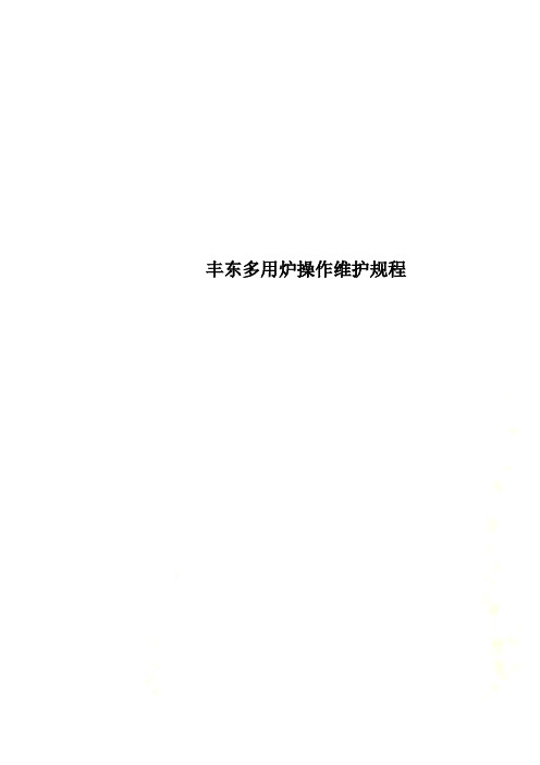
Goodman Manufacturing Company, L.P .2550 North Loop West, Suite 400Houston, TX -or-The Furnace Twinning Kit (FTK) provides the means for two (2) Amana ® brand or Goodman ® brand gas furnaces containing an Integrated Ignition control to operate at the same time from a single thermostat. The two furnaces to be “twinned” must be exactly the same model with their circulating air blowers set to deliver the same air flow at the same time. The furnaces may deliver different CFMs in the cooling mode, if appropriate. THIS KIT CANNOT BE USED TO CONTROL MORE THAN TWO (2) FURNACES. When properly installed, these furnaces will achieve the operational and performance specifications described in the installation instructions. For items not covered in this manual, follow the installation instructions shipped with the furnaces.This Twinning Kit Installation Instruction is divided into five sections. Section I deals with furnace opening sizes, recommended filter sizes and maximum CFM per furnace. Section II details the installation of the twinning kit. Section III details the sequence of operation. Section IV provides checks and possible repair procedures. Section V provides a point-to-point wiring diagram.Bottom ReturnIn most cases, bottom return air to both upflow furnaces will be more practical. When bottom return air is used, the furnaces should be set as close together (0 to 3 inches) as is practical. This separation distance is variable, depending upon the needs of the particular job.See furnace specification sheet for furnace opening sizes, recommended filter sizes, and maximum CFM per furnace.Side Return (One Return per Furnace)This is applicable only for the upflow models with less than five tons of airflow.P REFERRED M ETHODPlace the furnaces close together and install a return air drop to the out-side of each furnace (Figure 1).Figure 1 - [Preferred Method] Single-Side Return Per Furnace SideCutouts are 14" x 23" (All Furnaces)A LTERNATE M ETHODThe alternate method is used when the installer is forced to use one re-turn for two furnaces (Figure 2). The maximum required spacing between the furnaces is 30 inches apart (approximately 28 x 24 return trunk duct).F URNACE T WINNING K ITI NSTALLATION I NSTRUCTIONSNOTE: NOT FOR USE WITH TWO-STAGE VARIABLE SPEED FURNACES OR WITH 2-STAGE CONDENSING UNITS.SECTION 1 GENERAL INFORMATIONIt is very important to properly size ductwork and to supply appropriate filters for your furnaces. There are four possible ductwork configurations for twinning your furnaces:•Bottom Return•Side Return - One Return per Furnace •Two Side Returns •Top Return IMPORTANT NOTE: Back return duct installations to furnaces are NOT permitted. Back return installations constrict airflow which leads to poor performance and equipment damage. Back return installations are con-sidered improper installation and will void warranty coverage.GENERAL NOTES•Maximum CFMs are limited by a maximum filter velocity of 600 feet per minute, or by circulator high speed at 0.5 inches External Static Pressure (ESP) (whichever CFM is lower). THIS REQUIRES A HIGH VELOCITY FILTER. THROWAWAY FILTERS MUST NOT BE USED.If using anything other than a permanent high velocity filter, consult filter manufacturer recommendations for maximum allowable veloc-ity.•Actual CFM at the job should be established by carefully setting the furnace input and measuring the temperature rise. The ESP/CFM Tables in the furnace specification sheets and installation manuals are based on side return(s) for a single furnace. For twinned installa-tions - especially those with bottom return - the relationship between ESP and CFM may be different. The most accurate way to estimate airflow on twinned installations is to use temperature rise:CFM =BTUH Input1.085 x (Supply Air Temperature - Return Air Temperature)•Cooling CFM should be 350 to 450 CFM per nominal ton of cooling capacity. Heating CFM must produce a temperature rise within the range(s) specified on the furnace nameplate.©1998-2006 Goodman Manufacturing Company, L.P.Effective: March 2006Part No. IO-656Printed in USAFigure 2 - [Alternate Method] Single-Side Return per FurnaceSide Cutouts are 14" x 23" Furnaces are 30" ApartTwo Side ReturnsTwo side returns per furnace is ordinarily used when only 8 or 10 tons of cooling are required and where a bottom return is not practical. The fur-naces should be from 24 to 30 inches apart. Two side returns are applicableonly for upflow models with five tons of airflow.Figure 3 - Two Side Returns Per Furnace SideCutouts are 14" x 23 " (All Furnaces)Top ReturnWhen counterflow furnaces are twinned, the return air must enter through the top of the furnace.See the furnace specification sheet for minimum plenum height and maximum CFMs per furnace. Filter racks areincluded with the furnaces.Figure 4 - Twinned Counterflow Furnaces"A" = Minimum Plenum Height Furnaces from 0 to 30" ApartSECTION II TWINING KIT INSTALLATIONThis Installation Kit includes:ABBTwinning Kit Item Quantity DescriptionA 1Johnson Controls Y88FA-3 Twinning ControlB 2Fan Sensor Field Supplied Material 2 - #6 Screws 3/4" long18 Gauge 5-Wire ConductorTools Required 1/4" Nut Driver Drill3/32" Drill BitSmall Regular (Common) ScrewdriverBefore Installing the Twinning KitThere are important items which must be determined before installing the twinning kit. Read all of these instructions before you begin install-ing either furnace.Continuous Fan OperationFurnaces that are twinned using this kit cannot be setup for heating-cooling-continuous fan speed operation. When the furnaces are set for continuous fan operation, it will be at the cooling fan speed. This applies to models using 50A50-288, 50A55-288, 50T55-288, 50A65-288 controls only. Models using 50A55-289 or 50A65-289 controls are set for continu-ous fan operation at the heating fan speed.Condensate DisposalWhen installing condensing furnaces, be sure to plan for adequate con-densate drainage. This is especially important on counterflow installations. Follow the condensate disposal piping directions shipped with the fur-nace.Unit WiringThis kit allows the furnaces to be placed a maximum of five feet apart. Wire routing between furnaces is the same for any type furnace being installed. IMPORTANT NOTE: Any excess wires must be routed and secured to prevent becoming entangled in either blower or damaged by either set of burners.Kit Installation1.Disconnect all electrical power to unit.2.Find a location for mounting the twinning control. The side of thereturn section of the furnace cabinet or on the return air duct would be adequate locations.NOTE: The control should be mounted in a location that allows ac-cess to the terminals for wiring and servicing and keeps wire lengths to a minimum.3.Drill two holes according to the following illustration (Figure 5).2.05" 4" 6.76"6.20"4.56"Figure 5Mounting Hole Locationsing two #6 3/4-inch long screws (field-supplied), mount the twin-ning control vertically with the label right side up. Ensure the screws are located in opposite corners of the control. Do not over tighten the screws. DO NOT expose the control to water or temperatures below -40°F or above 120°F.5.Designate one of the furnaces as furnace #1 and the other as fur-nace #2.6.Connect furnace #1’s ignition control thermostat connectors: C, R, W,Y, and G to an 18 gauge 5-wire thermostat cable.7.Route the cable up through the blower deck and out the thermostatwire hole on the side of the cabinet. Connect the wires to the corresponding terminals on the furnace #1 section of the twinning control.8.Repeat steps 6 and 7 for furnace #2. Fan Sensor Wiring Installation1.Remove the backing paper from the adhesive backed Fan Sensor andattach to the #1 furnace control mounting plate next to the furnace control module.2.Route the three wire cable along the same path as the thermostatwiring to the twinning control.3.Connect the three wires to the corresponding FAN/LED SENSOR IN-PUTS on the furnace #1 section of the twinning control. The cable can be cut to a convenient length.4.Locate any two fan motor speed tap wires (red, black, blue, or or-ange), even if they are unused.IMPORTANT NOTE: To prevent damage to the fan sensor do not choose the WHITE “neutral” lead wire.5.Connect one of the two motor leads to one of the black wires from thefan sensor with the “Y” terminal provided. Repeat this step for the other fan lead.6.Connect the “Y” terminal to the original location of the motor speed tapwire.Note: The connector should be taped if the motor speed tap wire is not connected to the furnace control module.7.The two white wires attached to the fan sensor must be taped orwire nuts added to prevent accidental connections. These white wires have no connections.8.Repeat steps 1 through 7 for furnace #2.Thermostat Wiring InstallationImportant Note: The system thermostat that controls the conditioned space should not have a current draw higher than 25 milliamps.1.The system thermostat connects to the 6-terminal strip on the oppo-site side of the Twinning Control from the furnace inputs. The control allows the use of a two stage heating and cooling thermostat. If a single stage heating or cooling thermostat is used the W1 and W2 (1 stage heating) or Y1 and Y2 (1 stage cooling) must be jumped to-gether. For thermostats that require a “common” connection a “C”terminal is provided.2.The heat anticipator in the room thermostat must be correctly adjustedto obtain the proper number of heating cycles per hour and to prevent the room temperature from “overshooting” the room thermostat set-ting. Heat anticipator must be set at 0.16 amps.SECTION III SEQUENCE OF OPERATIONSingle Stage ThermostatOn a system call for heat a relay closes both blower (R-G) circuits, pow-ering the blowers of both furnaces (continuous fan speed). One second later, relays close the heating (R-W) circuits of both furnaces. In 30 or 45 seconds after the furnaces fire, the blowers will switch to the heating speed. When the call for heat is satisfied at the thermostat, both (R-W) circuits will immediately open. Following approximately a 65 second delay, the fan (R-G) circuits will open.For cooling operation, the sequence is identical but with the R-Y circuits activated.NOTE: In the heating mode, if the furnace control module blower off timing is longer than the Twinning Control's 65 seconds, the blower(s) will con-tinue to operate in the heating speed until the furnace control module blower off delay is satisfied.Two-Stage ThermostatOn a first stage call for heat, a relay will close both blower (R-G) circuits as in the single stage operation. One second later, a relay will close the heating circuit (R-W) of furnace #2 only. In 30 or 45 seconds after the furnaces light, the blower of furnace #2 will switch to the heating speed. When the call for heat is satisfied, the (R-W) circuit will open and the 65 second Twinning Control fan off delay begins. The furnace #2 blower will operate in the heating speed until the furnace control module blower off delay is satisfied, then the blower will switch to the continuous fan speed.NOTE: If the furnace control blower off delay is longer than the 65 second Twinning Control off delay, the Twinning Control will turn off the blowers.The blower for furnace #1 will shut off, and since the blower on furnace #2 is still running, the blower for furnace #1 will reenergize in the continuous fan speed. This process will continue until the furnace control blower off timing is satisfied and both blowers are running in the continuous fan speed. The Twinning Control will then simultaneously turn off both blowers.To prevent this operation, set both furnace's heat off delay time to 60seconds.On the next stage 1 call for heat, furnace #1 is signaled to heat. This sequence alternates on successive cycles balancing run times on the furnaces.If a stage 2 (W2) call for heat is received at any time W1 is activated the R-W circuit of the non-firing furnace closes.If both stages energize or deenergize simultaneously, operation is identical to single stage operation above.Two stage cooling is analogous to staged heating but activates the R-Y cir-cuits. The blowers will have a 65 second off delay in the cooling speed.Abnormal ConditionsIf only one blower is sensed “ON” for more than four seconds while a thermostat input is present, both furnaces will deenergize and the on-board LEDs are activated. This lockout condition can be reset by turning the thermostat to the OFF position or by turning the power OFF then back ON for both furnaces for at least one second and returning to the desired function. If, when no thermostat input is present, only a single blower is sensed, the blower circuits (R-G) close to both furnaces for 65 seconds and then open. If the unbalanced condition (one blower sensed), still ex-ists, the sequence repeats.Diagnostic LED Flash SequenceThe on-board LED activates with a blower failure on furnace 1, 2, or both.If the furnace blower failure is on furnace 1, the LED will flash once with a two-second off interval between flashes.If the furnace blower failure is on furnace 2, the LED will flash twice with a two-second off interval between flash sequences.If the furnace blower failure is on both furnaces, the LED will flash three times with a two-second off interval between flash sequences.SECTION IV CHECKOUT AND REPAIRSStartup ProcedureRefer to the Installation Instructions provided with the furnace for proper operation and startup procedures after installing the twinning control. If that information is not available, follow these instructions to ensure all components function properly:1.With the gas and thermostat off, turn ON power to the furnaces.2.Turn the thermostat to a high setting and verify that both ignition con-trols go through the operating sequence to a shutoff condition.Note: The burners will not light because the gas is off.3.Turn OFF the thermostat.4.Turn ON the gas and purge gas lines of all air.5.Check for gas leaks with a soap solution.6.Turn the thermostat to a high setting and verify successful ignition and a normal run condition for at least three minutes.7.Do a leak check on all pipe joints downstream of the gas valve with a soap solution.8.Turn the thermostat down for at least 30 seconds and then back up again. Verify successful ignition at least three times before leaving the installation.Repairs and ReplacementDo not attempt field repairs. Use only an exact or factory recommended replacement control.SECTION V POINT-TO-POINT WIRING DIAGRAM。
IPSEN易普森RTQF-10-ERM多用炉操作指南
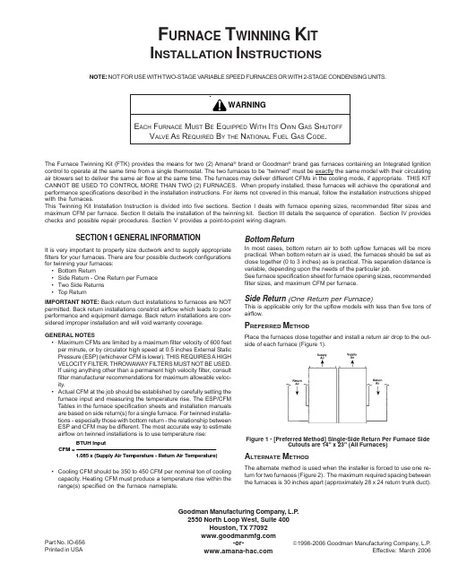
一、准备工作1、多用炉生产线周围,料车行走区域内不得有异物,生产线场地不得有易燃易爆物品,消防器材必须放置在明显的位置。
2、工件进炉前应首先检查空炉温度,设定在900—930C为宜,以免工件进炉造成降温过低。
3、将待处理工件,根据大小结构不同,装入专用或合适的料盘/料筐。
装炉量一般情况下以最大装炉量的70-80%为佳,最大不能超过1000Kg (为毛重,含料盘/料筐重量)。
然后送入清洗机清洗并烘干,或在回火炉里预热。
二、启动多用炉生产线的辅助设施1、接通主电源开关,检查电压值为380± 5%V。
2、启动循环水系统,使供水压力为0.2-0.3MPa。
3、启动压缩空气系统,使压缩空气出口压力为0.5-0.7MPa,主炉单机工作压力最小不得低于0.6MPa。
4、所有压力传感器必须设定在适当的工作压力上。
5、检查液化器/丙烷压力,使其出口压力为20-30KP&6、检查N2压力,使其出口压力为20-40KPa。
三、启动设备1、检查各限位开关是否准确可靠。
2、检查料车的运行状态及各停车位置是否准确无误。
3、确认设备处于启动前的状态(内炉门关闭,外炉门处于外推状态,并有100伽缝隙,淬火升降台处于装载位,炉链,附推处于初始状态,各冷却水阀均处于打开状态)。
4、将油槽温度限制器设定在150C,调节风扇及氧探头的冷却水流量,使其出水口水柱直径约为5-6mm出水口水温为30-40 C为宜。
冷却水流量不宜过大,否则易使风扇及氧探头的水入口处出现温度过低,在对应的炉膛内壁易形成水冷凝。
5、调节淬火室炉壁冷却水的水流大小,观察出水口的出水状态为控水状态即可(一旦调节好,以后不必再动)6、 检查淬火油槽的油位,使其达到油标指定的油位,油位过低,必须及时添加。
7、 接通控制柜上的主电源和控制电源开关,待 PLC 正常运行后按故障复位按钮。
8将加热器超温控制器设定在1100^0 (根据使用工艺的最高温度)9、加热室超温监控的上限设定在最高工作温度以上20-30 C,通过按“报警关/灯测试”和“故障复位”按扭使超温保护起作用。
箱式多用炉安全操作规程
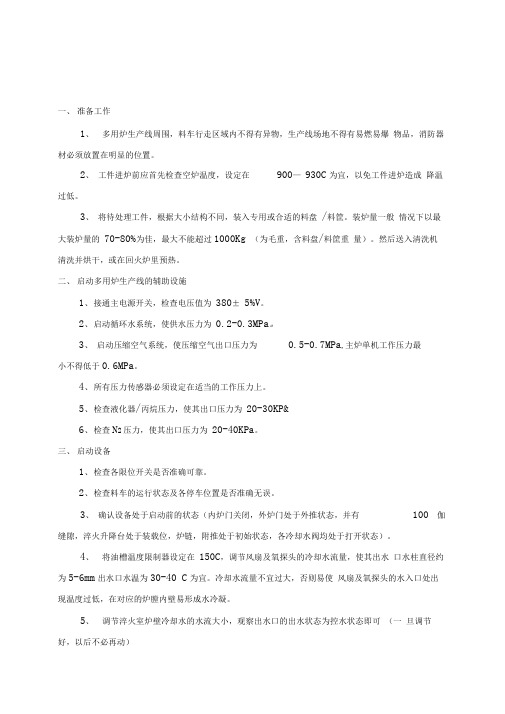
箱式多用炉安全操作规程箱式多用炉安全操作规程1、操作工必须经培训后方可持证上岗操作。
2、操作工必须严格按照《滴注式气体渗碳氮化炉自动线使用说明书》要求操作。
3、工作时严禁离岗,做到及时巡检,掌握好设备运行状况,确保设备安全运行,并按规定做好记录。
4、每周检查确认安全装置的有效性。
5、禁止在过载、超负荷下使用设备。
对体积小,表面积大的产品必须适当减少装炉量。
6、禁止炉膛直线升温。
7、炉膛内要始终保持清洁。
8、滴注剂及用完的空罐都应远离火源。
9、禁止往加热器罩和变压器上溅水,禁止在其旁边堆放物品。
10、淬火油内不能含水等杂质,油温使用温度不得超过95℃。
在加入新油或长时间未用的情况下,使用前必须进行除水处理:敞开前门,打开油搅拌,将淬火油加热至105℃,保温24小时,期间保持轻微搅拌,确保将油中所含水份蒸发掉。
11、结冰天气,长时间停炉要排放管路中的残水以防冻坏部件及管道。
12、加入炉内的工件要确保干燥、清洁。
13、工件固定要可靠,以防落入炉内或油池内。
14、操作时要注意:(1)确保引火烧嘴燃烧和前门小门处有明火;(2)经常检查排水集合器,看冷却水是否正常流动;(3)通过检查压力表的读数,确保压缩空气按照规定的压力供气;(4)检查油量是否充足;(5)检查滴注剂是否以正常的流量滴注;(6)检查加热器的电源电压是否符合要求;(7)检查加热电流是否三相平衡,能否达到规定的电流;(8)在“自动”、“单动”操作中关掉所有不必要的开关,禁止碰摸不必要的操作开关和按钮;(9)在“单动”操作中,确保操作开关一个一个地操作;(10)在“自动”操作中,确保相应设备和推拉车具有自动操作的能力(限位开/关指示灯的开关状态正常)。
15、停电时要注意:(1)确保安全,不让空气进入炉内,以免发生爆炸。
(2)在保证安全的前提下,考虑不损坏设备和不让工件氧化。
16、停炉时要注意:(1)停炉前必须具备两个条件:炉温低于850℃,油温低于80℃。
易普森多用炉操作参考
易普森工业炉(上海)有限公售后服务部郑文政多用炉操作参考(个人总结)Carb-O-Prof1. 启动:将控制柜门上的电源开关扳至ON后,打开下层控制柜门,启动UPS(不间断电源),确认电源指示灯亮(绿灯),再打开上层控制门,按下主机电源开关,确认主机启动灯亮(绿、红灯同时亮),待显示屏显示Carb-O-Prof后,关闭控制柜门。
2. 联机:在造气前必须将电脑设置为联机状态,方法如下在主菜单中用上/下光标键(红色条代表当前状态)选择过程控制(第二条),按回车键;用左/右光标键将红色条套在ON-LINE上,按F7(SAVE)保存。
3. 参数修改:当CP处于联机状态下,则TP-170的温度设置无效。
如需修改温度和碳势则只能CP上操作,方法如下修改加热室的温度和碳势:在过程控制(Process control) 菜单中选择加热室(Heating chamber),屏显中的F3为温度修改、F7为碳势修改,按下对应健后,在屏显的蓝色光标中输入需修改的数值按回车键即可;在过程控制(Process control) 菜单中选择淬火室(Quench chamber),屏显中的F3为温度修改,按下对应健后,在屏显的蓝色光标中输入需修改的数值按回车键即可。
4. 调用工艺程序:在过程控制(Process control) 菜单中选择炉料文件(Charge file)按回车键(如左上角出现stop,按F2即可激活),再在屏显中的第一栏(Programme No.)内输入对应的工艺号、在屏显中的第二栏(Nomber of charges) 内输入对应的炉次后按F7保存,待有装载信号后即可进行工件处理(如遇有工艺号调用错误时,可在Charge file中将光标标在需删除条目上按F8后再按回车即可,并重新调入正确的工艺号)。
5. 工艺过程监控:程序段/时间:第1栏:当前执行的程序段的持续时间;第2栏:从第1程序段到当前时刻所消耗的时间;第3栏:从当前时刻到最后一个程序段结束所需时间。
多用箱式淬火炉操作手册培训课程(ppt83张)

PowerMax Furnaces Corp
操作手册
UBQ36-48-36G加热炉
BEST SOLUTIONS FROM ONE SOURCE
PowerMax Furnaces Corp
安装
收货
• 在收到设备时,检查包装是否有损坏。如果损坏,打开 板条箱检查设备。 • 注:因运输导致任何损坏必须马上报告给收货人并且提 出损坏赔偿等。
拆箱
BEST SOLUTIONS FROM ONE SOURCE
PowerMax Furnaces Corp
BEST SOLUTIONS FROM ONE SOURCE
PowerMax Furnaces Corp
IV.
•
安全
•
保障人员安全,它必须给从事任何一种重要程序停工,当在这个设备上进行 任何一种维护时。在整个工作期,淬火前厅和淬火升降机安全插脚和炉门安 全销必须在适当位置,当人员在设备内部工作时。 全部驱动器防护装置必须是全部在工作状态内,除了进行设备维护的时候。 那时与任何防护装置是无关的,设备必须是锁定的,防止对维护人员产生伤 害。
III. 炉子、淬火槽安装
BEST SOLUTIONS FROM ONE SOURCE
PowerMax Furnaces Corp
A.淬火槽
• 确保购买者完全按照AFC-HOLCROFT/ POWERMAX的地基图一致的地面和基础工 作。 • 注:全部的地面和路轨高度和平行必须是+/- 1/8"。检查索箍和确保全部的 高度依照运输的尺寸。 • 由AFC-HOLCROFT/POWERMAX建筑的平面设计图,展示淬火槽的中心线。检查 淬火槽的内部,确保全部的组分恰当的安装和保护。移除任何阻拦或其它杂 质。确保淬火槽没有水。 • 淬火槽移动到位置。薄垫片和炉膛水平高度对中转车。设置炉子中转车与淬 火前厅操纵链轨之间1/2"间隙,经AFC-HOLCROFT/POWERMAX平面建筑设计图 。确定那车的滚筒高度和淬火槽排列。在完成薄垫片和水准测量后,用100% 水泥浆填在淬火槽之下后继续进行下列各项: • 安装淬火升降机气缸和限位开关装配。 a.连接升降机杆U-形钩到气缸和指示杆。 注: 升降机U-形钩是拴在活塞杆上,防止气缸杆从U-形钩上松开
多用炉操作作业指导书

多用炉操作作业指导书一、目的本指导书旨在规范多用炉的操作流程,确保设备的安全运行,提高生产效率和产品质量。
二、适用范围本指导书适用于公司内所有使用多用炉的操作人员。
三、操作前准备1.检查设备外观,确保设备完好无损,无明显异常。
2.检查电源、气源、水源等连接是否正常,无泄漏现象。
3.检查炉膛内是否有杂物,如有,应清理干净。
4.检查温度控制系统、气氛控制系统等是否正常。
四、操作步骤1.启动电源,开启多用炉的控制系统。
2.根据生产需求,设定炉温、气氛、加热时间等参数。
3.将待处理的物料放入炉膛内,注意物料应均匀分布,避免局部过热。
4.关闭炉门,启动加热程序。
5.在加热过程中,密切关注温度、气氛等参数的变化,确保其在设定范围内。
6.到达预定时间后,关闭加热程序,打开炉门,取出物料。
7.对取出的物料进行检查,确保其达到质量要求。
五、注意事项1.操作过程中,操作人员应佩戴好防护用品,如手套、防护眼镜等。
2.严禁在炉膛内放置易燃、易爆物品。
3.如发现设备异常情况,应立即停止操作,并及时上报维修人员。
4.操作结束后,应清理炉膛及周围环境,保持整洁。
六、维护与保养1.定期对设备进行清洁,去除炉膛内的积碳和氧化物。
2.定期检查设备的各部件,确保其完好无损。
3.如发现设备故障,应及时联系专业人员进行维修。
七、记录与报告1.每次操作后,应记录操作时间、温度、气氛等参数。
2.如发现异常情况或产品质量问题,应及时报告给上级或相关部门。
海尔电器空气炉手册说明书
Eco 50°
1) 4:35 2) 0,849 3) 9,5
Silence 50 1
1) 4:00 2) 1,050 3) 11,0
Glass 40°
1) 1:33 - 1:38 2) 0,800 - 0,850 3) 12,0 - 14,0
Express 65° - 1h Express 45°
1) 1:00 2) 1,300 3) 10,5 1) 0:29 2 2) 0,800 3) 10,5
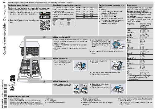
4. Place the lid back on the dispenser and turn to close.
Adding rinse aid
1. Press the catch on the lid of the dispenser for rinse aid and lift .
2. Add rinse aid up to the
gramme.
7. To cancel the programme, press
for
approx. 4 seconds.
The programme is cancelled and ends after ap-
prox. 1 minute.
Cleaning filters
1. After each wash check the filters for
2. Pull up the lower spray arm to remove.
3. Check the outlet nozzles on the spray arms for blockages under running water and remove any foreign bodies.
- 1、下载文档前请自行甄别文档内容的完整性,平台不提供额外的编辑、内容补充、找答案等附加服务。
- 2、"仅部分预览"的文档,不可在线预览部分如存在完整性等问题,可反馈申请退款(可完整预览的文档不适用该条件!)。
- 3、如文档侵犯您的权益,请联系客服反馈,我们会尽快为您处理(人工客服工作时间:9:00-18:30)。
TQF-10-ERM多用炉操作指南一、准备工作1、多用炉生产线周围,料车行走区域内不得有异物,生产线场地不得有易燃易爆物品,消防器材必须放置在明显的位置。
2、工件进炉前应首先检查空炉温度,设定在900—930℃为宜,以免工件进炉造成降温过低。
3、将待处理工件,根据大小结构不同,装入专用或合适的料盘/料筐。
装炉量一般情况下以最大装炉量的70-80%为佳,最大不能超过1000Kg(为毛重,含料盘/料筐重量)。
然后送入清洗机清洗并烘干(见装卸料操作规程),或在回火炉里预热。
二、启动多用炉生产线的辅助设施1、接通主电源开关,检查电压值为380-400V。
2、启动循环水系统,使供水压力为0.2-0.3MPa。
3、启动压缩空气系统,使压缩空气出口压力为0.5-0.7MPa,主炉单机工作压力最小不得低于0.5MPa。
4、所有压力传感器必须设定在适当的工作压力上。
5、检查液化器/丙烷压力,使其出口压力为10-40KPa。
6、检查N2压力,使其出口压力为10-40KPa。
三、启动设备1、检查各限位开关是否准确可靠。
2、检查料车的运行状态及各停车位置是否准确无误。
3、确认设备处于启动前的状态(前炉门、内炉门关闭,外炉门处于外推状态,并有150㎜缝隙,淬火升降台处于上工位,炉链处于初始状态,各冷却水阀均处于打开状态)。
4、将油槽温度限制器设定在150℃,调节风扇及氧探头的冷却水流量,使其出水口水柱直径约为5-6mm,出水口水温为30-40℃为宜。
冷却水流量不宜过大,否则易使风扇及氧探头的水入口处出现温度过低,在对应的炉膛内壁易形成水冷凝。
5、调节淬火室炉壁冷却水的水流大小,观察出水口的出水状态为控水状态即可(一TQF-10-ERM多用炉操作指南旦调节好,以后不必再动)。
6、检查淬火油槽的油位,使其达到油标指定的油位,油位过低,必须及时添加。
7、接通控制柜上的主电源开关“Main switch”、控制电源开关“APT”(1=开0=关),待PLC正常运行后按故障复位按钮。
8、将加热器超温控制器设定在1050℃。
(根据使用工艺的最高温度)9、加热室超温监控的上限设定在最高工作温度以上20-30℃,通过按“报警关/灯测试”和“故障复位”按扭使超温保护起作用。
四、加热1、将主炉外炉门左侧操作面板上的加热室风扇开关设置在“2”的位置。
(1=关、 2=开、 ST=手动)2、通过TP170A触摸屏将加热室温度设置为100℃,保温1小时后,然后将加热室温度设置为250℃,保温4小时,以后每隔2小时将加热室温度提高100℃,直到850℃再保温1小时(整个加热过程如下图所示),以上升温速度仅适用于停炉时间很短(1-2天)的情况,如果停炉时间较长也可适当降低升温速度,即将每个保温时间延长。
℃850℃750℃1h650℃2h550℃2h450℃2h350℃2h250℃2h100℃4h1h冷炉升温过程示意图TQF-10-ERM多用炉操作指南3、打开液化气阀门,关闭外门,点燃排气口尾气长明火的点火烧嘴。
4、启动C/N(气氛)面板启动C/N面板须满足以下六个条件:※设备处于“on-line”(联机,即PC机与PLC建立通讯联系)状态;※炉温必须超过750℃(一般在850℃以上);※有氮气通入且流量浮子高于传感器;※尾气长明火已点燃;※压缩空气在规定范围内(不能低于0.5MPa);※液化气或丙烷供应正常;○1将控制系统设置在“联机”即“ONLINE”状态;将CO控制方式设置在“计算”即“Calculated”状态;将填料文档设置在“Manual”及“手动”状态。
○2打开丙烷管路上的手动阀。
○3打开氮气管路上的手动阀,使氮气流量计的流量在4-5m3/h。
○4将空气电动阀的开关设定在“AUTO”(自动)的位置。
○5将内炉门开关“Inner door”置于“1”开的位置,待内门打开后,再将外门开关“Outer door”置于“1”开的位置,待火帘点燃后,外门打开。
○6同时按下控制柜上的报警关/灯测试和复位按扭,并保持一段时间。
○7按下“保护气体开”按扭(“protactive gas ON”),并保持一段时间,此时如满足条件,电磁阀打开,空气鼓风机启动,调节丙烷流量(0.2-0.4m3/h),同时观察炉膛进气孔处有燃烧的火焰时,说明C/N面板启动成功,此时关闭内炉门和外炉门,C/N面板启动程序完成。
○8观察C/N面板上的各种介质的常规流量(设定好后不要随意再调整任何阀)。
氮气流量:4-5m3/h(启动C/N前充氮气的流量)丙烷常规流量:0.2-0.4 m3/h炉门打开时丙烷流量:0.3-0.5 m3/h氧探头参比空气流量:20ml/minTQF-10-ERM多用炉操作指南氧探头清洗时空气流量:80ml/min○9如果所需丙烷压力以及鼓风机压力低于设定值,15秒后C/N面板停止,并出现故障报警(“保护气开”按扭指示灯会闪烁,控制柜上的故障灯和模拟图相应指示也闪烁)此时可调节相应介质流量或调节设定压力,然后再重新启动C/N面板。
○10C/N面板突然关闭时的重新启动当出现以下五种情况时,C/N面板随即关闭,且相应指示闪烁。
※加热室温度降到750℃以下,“750℃延时Ⅰ”和/或“750℃延时Ⅱ”安全时间结束(大约1.5h后)。
※丙烷压力低于设定的下限或鼓风机空气压力低于开关的设定值。
※压缩空气低于外炉门压紧气缸压力监控的设定值(大约0.4MPa)。
※炉门打开时间过长。
※停电。
○11如果C/N面板具备启动条件,而且炉门也没有打开过,关闭间隔时间又不超过30分钟,则启动C/N面板不必打开任何炉门而只需直接按“保护气开”按扭和控制柜“故障复位”按扭即可。
如果时间超过30分钟,则设备必须先要仔细排气,才可按照C/N面板启动程序,重新启动C/N面板。
五、工件装炉(自动方式)1、将控制柜上的方式开关置于“操作”方式,运行工艺时不得随意改动。
2、通过计算机在相应的“菜单”中确定所要使用的炉号。
3、在TP170触摸屏上设置工艺时间21、22、27和28时间为15-30分钟(炉门安全和清洗淬火室时间),第一次设定后不得随意改动。
4、进入相应的“菜单”,调用对应的程序(见《装炉程序调用步骤》)。
程序调用且工艺时间21、22、27和28计完后,控制系统给出装料信号,铃响,“装料”“load”按扭亮。
5、通过装卸料车、传送料台将已清洗、烘干过的工件送往炉子外门,使装卸料车对准炉门,此时应特别注意料盘必须与料车中线对正且平行于料车两边,(两边间隙一样)!!!TQF-10-ERM多用炉操作指南6、按下装料“load”按扭,30秒后前门打开,用料车将工件装入加热室中,然后再次按下装料“load”按扭,前门关闭,热处理工艺程序自动进行。
六、工件由加热室传送到淬火室1、在工件由加热室传送到淬火室以前5分钟,检查压缩空气压力是否在规定压力范围内。
2、工件在加热室的程序执完成后,推进链首先空转半周,将热链导入非受力状态,此时内门自动升起,然后炉链将工件推送到淬火室,内门自动降下关闭。
3、对于工件在加热室到淬火室油冷而言,在工件淬火入油中之前,淬火油温度应达到工艺设定值,油热交换器启动时,油压为0.15-0.25MPa,水压为0.04-0.07MPa,设定好后不得随意调整。
七、工件出炉1、淬火室的程序完成后,炉子控制系统给出卸料信号(铃响,卸料按钮“Unload”亮)。
2、将装/卸料车开到待出炉的外炉门处,对准外炉门(车自动停止位置)。
3、按下卸料“Unload”按钮,火帘点燃,外炉门打开,用装/卸料车将工件从淬火室拉到装/卸料车上。
4、再次按下卸料“Unload”按钮,外炉门关闭,程序结束。
八、关闭炉子1、关闭C/N面板关闭C/N面板的必备条件※加热室的温度必须在750℃以上。
※尾气长明火必须处于工作状态。
○1用相应的手动开关打开内炉门、外炉门和前炉门。
○2关闭通向C/N面板控制系统管路上的所有手动阀门。
15秒后,C/N面板关闭。
故障指示灯和模拟图相应指示均会闪烁。
○3按下“保护气体关”“Protective gas off”按扭,C/N面板关闭。
○4将加热室风扇开关置于(“start”)手动的位置并保持一段时间,使加热室处于通TQF-10-ERM多用炉操作指南风状态,以吹出炉膛中残存的气氛。
○5观察并确认炉底板缝隙中及炉膛内没有火焰冒出时,关闭前炉门和内炉门,外门落在150mm的顶杆上,气缸在外推位置不要压紧炉门,然后关闭尾气点火嘴和火帘点火嘴,并把计算机设置为脱机状态。
2、停机○1关掉计算机电源和UPS电源。
○2关掉炉子保护气供应管路上的手动阀。
○3在TP170A接触屏上将加热室温度定为0℃,也可将超温监控温度设置为0℃,采用自然降温。
○4在TP-170A触摸屏上将油循环开关关闭,使搅拌电机停止工作。
○5当炉温降至200℃以下时,关闭风扇冷却水,将风扇开关置于“1”(关)的位置,使风扇电机停止工作。
○6关闭丙烷管路阀门,关闭压缩空气阀门,关闭氮气阀门。
○7关闭控制柜上的控制电源开关和主电源开关“Main switch”。
九、手动操作(调整方式)1、将控制柜上的方式开关置于“调整”方式,点燃尾气长明火,故障复位。
2、将升降台开关置于“2”时,升降台下降;将升降台开关置于“1”时,升降台上升。
3、将内炉门开关置于“1”,打开内炉门。
4、升降台只有处于上位,才可以对推进链进行操作。
5、将推进链开关置于“1”,推进链运行0—1/2。
6、将推进链开关置于“2”,且内门已经打开时,推进链运行1/2—1,到达原位后停止。
7、将内炉门开关置于“0”,关闭内炉门。
8、将外炉门开关置于“0”,关闭外炉门。
十、几种特殊情况及处理办法1、周末停产时的炉子状态TQF-10-ERM多用炉操作指南○1如果短期停产,在炉子中没有工件的情况下(一般指待料状态),可将加热室的温度设定在900℃,将碳势设置在0.4%C,空炉运行(联机控制)。
○2如果停产时间较长,待工件出炉后,可关闭C/N面板,然后将加热室温度设定在850℃(脱机控制),炉子外门落在顶杆上并保持外推状态。
2、停电及设备故障状态下炉中工件的处理※停电时最重要的是迅速启动备用水源,确保炉子风扇、氧探头冷却水供应。
○1停电时间少于20分钟,来电后计算机仍处于联机状态。
直接按下“保护气体开”(“protective gas ON”)按钮重新启动C/N面板,此时系统继续执行原程序,须由有关人员对执行程序做相应修改,以完成后续过程。
○2停电时间较长,工件停在加热室中,炉温降到750℃以下,计算机不要联机。
※此时应保证有足够的氮气通入,来电后若要将工件直接出炉时,可先在TP-170A 触摸屏上分别选择加热室工艺方式“1”和淬火工艺方式“1”(空冷)。