钛码锐码-TM22XX模块数据手册
RM22JA31MR模块式测量与控制联络器数据手册说明书

Switching capacity in VA Measurement range
Zelio Control
Modular measurement and control relays
Current control relay
RM22JA
Overcurrent or undercurrent detection Overcurrent or undercurrent in window mode
Product datasheet
Characteristics
RM22JA31MR
Current control relay 4mA…1A, 2 C/O
The information provided in this documentation contains general descriptions and/or technical characteristics of the performance of the products contained herein. This documentation is not intended as a substitute for and is not to be used for determining suitability or reliability of these products for specific user applications. It is the duty of any such user or integrator to perform the appropriate and complete risk analysis, evaluation and testing of the products with respect to the relevant specific application or use thereof. Neither Schneider Electric Industries SAS nor any of its affiliates or subsidiaries shall be responsible or liable for misuse of the information contained herein.
Optex CD22系列迷你激光位置传感器用户手册说明书

Smallest displacement sensor in class* A mong devices equipped with displays in the 1 μm repeat accuracy class. Optex FA examination performed November 2015.Newly added amplifier unit that can be connected with CC-Link communication unitsBuilt-in amplifier & digital 4-digit displayFeaturing high performance functionality like high-end modelsRelated productsCC-Link communication UC1P .118Remote operation/calculation CDAP .450Specular reflection typeCD33P .47218 × 31 × 44 mm (W × D × H). The FASTUS CD22 series has achieved being the smallest displacement sensor in its class by adopting a new type of hybrid lens for the optical system and by integrating accumulated optical technology. By utilizing Optex FA’s know-how regarding the completion of measurement processing inside the sensor head, a feedback circuit that is the same as those on high-end displacement sensors has been equipped within the compact body.*Among devices equipped with displays in the 1 μm repeat accuracy class.Optex FA examination performed November 2015.Smallest in class*W18 × D31 × H44 mmPositioning for metal plate mountingDetection of presence/height of electronic componentsSlackness measurements for rubber materialsElectrode thickness measurement464Compact laser displacement sensor CD22 series Selection tableFor the pig tail type, please purchase an optional connector cable.When using a CDA amplifier unit, please select the RS-485 communication type.Regarding stainless steel housingtype (made-to-order)A type that features SUS316L for the housing can also bemade.ConnectorcablesDisplacement sensor amplifier unitCDA seriesOptionsDOL-1205-G02MCable length: 2 mDOL-1205-G05MCable length: 5 mDOL-1205-G10MCable length: 10 mCDA-M(master unit)CDA-S (slave unit)DOL-1205-G02M-RCable length: 2 m, robot cable typeDOL-1205-G05M-RCable length: 5 m, robot cable type* I mage shows DOL-1205-G02M. Robot cable type feature black instead of orange and shapes vary slightly.Features an organic EL display that can display clearly in bothJapanese and English.This external amplifier can be used for calculations using twoCD22 series units or connected to a CC-Link communicationunit.*For details, refer to page 450.Compact laser displacement sensor CD22 seriesFeaturesIdeal for robot mountingCD22 series models feature a compact and lightweight body, and because of their built-in amplifier, there are few limitations on installation space and wiring, meaning that sensors themselves can be mounted on robots or on moving parts.Connect with CC-Link to achieve “sensor visibility”By connecting a CDA series to a communication unit, connection to a CC-Link network is possible.It supports Mitsubishi iQ Sensor Solution (iQSS) and batch management of sensors can be performed easily with GX Works2.CC-Linkcommunication unit UC1Easy-to-see digital panelFeaturing an ultra-small body and easy-to-see built-in 4-digit digital panel meter.Confirmation of distance can be performed on the spot and the 4 operation buttons provide multi-functionality whileenabling easy operation.The housing features aluminum die-casting that suppresses measurement errors caused by temperatures or housing distortion.OUT: ON when output is ON ZERO: ON when zero reset is usedMANUAL: ON when "Extension mode"LASER: ON during laser emissionCC-Link communication unitUC1 series*For details, refer to page 118.The external amplifier unit enables remote operation and easy calculation settingWith its excellent visibility and operability, the external amplifier unit enables the CD22 series to be operated remotely even when mounted in narrow spaces such as inside machinery.Calculation of thickness and height differences can be performed easily using 2 sensor heads.Displacement sensor amplifier unitCDA series*For details, refer to page 450.Compact laser displacement sensor CD22 seriesHigh-accuracyWith the CD22 series, the causes of all measurement errors can be eliminated even in the case of workpieces in which highly accurate measurements were difficult thanks to “Tri-CORE” optimization technology that corrects receiving light waveforms by way of “digital sub-pixel processing”, a “high resolution electric shutter” and “unique algorithm”.Automatic sampling functionWith the CD22 series, in addition to normal receiving light quantity feedback, a “Sampling period: AUTO” mode has also been equipped that automatically adjust the sampling period when there are only low levels of reflected light from the workpiece.Thanks to this, high-speed measurements of even black workpieces and metal workpieces with low levels of reflected light are possible.Alarm hold functionAlarms may be generated during measurement due to small holes in the workpiece, etc.CD22 series models are equipped with an “alarmhold function” that enables the time until an alarm is identified to be set. It is possible to configure settings so that an alarm is not generated in the case of small holes, but is generated when there is no workpiece.During high-speed samplingresulting in some sections not being able to be measuredDuring low-speed samplingShape cannot be correctly obtainedworkpieces can be correctly obtainedWorkpiece in which receiving light quantity is decreased due Sampling period: When xedelectricalgorithmWhen alarm hold is not usedMeasurement not possible (9999)When alarm hold is usedAlarm holdCD22-15CD22-35 CD22-1000.21015Measurement distance (mm)L i n e a r i t y (%F S )200.10−0.1−0.2−0.3−0.4−0.50.30.40.50.220Measurement distance (mm)L i n e a r i t y (%F S )500.10−0.1−0.2−0.50.30.40.5−0.3−0.430400.25060708090110120130140100Measurement distance (mm)L i n e a r i t y (%F S )1500.10−0.1−0.2−0.3−0.4−0.50.30.40.5Black rubberStainless steel plateWhite ceramic (speci cation)Linearity characteristics data Low deviation depending on the workpieceCompact laser displacement sensor CD22 seriesSpecificationsAnalog output type¢Array Array<Measurement conditions>The measurement conditions are as follows unless otherwise designated: Ambient temperature: 23°C (normal temperature), Supply voltage: 24 VDC, Sampling period: 500 μs, Average number of times: 64, Center of measurement range, Measurement target: white ceramic.*1 A Class 1 type can also be made available (made-to-order product).*2 I n accordance with the FDA provisions of Laser Notice No. 50, the laser is classified as Class 1 or Class 2 per the IEC 60825-1 standard.*3 D efined with center strength 1/e2 (13.5%) at the center of measurement range. There may be leak light other than the specified spotsize. The sensor may be affected when there is a highly reflective object close to the detection area.*4 With an average of 512 times*5 In the case of the analog voltage output type, use a supply voltage of 12.0 VDC Minimum to obtain the proper output.RS-485 communication type¢<Measurement conditions>The measurement conditions are as follows unless otherwise designated: Ambient temperature: 23°C (normal temperature), Supply voltage: 24 VDC, Sampling period: 500 μs, Average number of times: 64, Center of measurement range, Measurement target: white ceramic.*1 A Class 1 type can also be made available (made-to-order product).*2 I n accordance with the FDA provisions of Laser Notice No. 50, the laser is classified as Class 1 or Class 2 per the IEC 60825-1 standard.*3 D efined with center strength 1/e2 (13.5%) at the center of measurement range. There may be leak light other than the specified spotsize. The sensor may be affected when there is a highly reflective object close to the detection area.*4 With an average of 512 times*5 Multi-drop connections by way of station number settings are not supportedCompact laser displacement sensor CD22 seriesI/O circuit diagram¢ Analog output type: With the NPN setting¢ Analog output type: With the PNP setting¢ Connector pin configuration(Sensor side)Brown 1Gray 3Black 2Blue 5White 4M12 connectorAnalog output typeBrown 1 12 to 24 VDC Black 2 Control output Gray 3 External input White 4 Analog output Blue 5 0 VRS-485 communication typeBrown 1 12 to 24 VDC Black 2 RS-485 (A)Gray 3 Not used White 4 RS-485 (B)Blue 5 0 VCompact laser displacement sensor CD22 series DimensionsSensorPig tail type Cable type(Unit: mm)Connector cables ¢ DOL-1205-G02M¢DOL-1205-G05M¢DOL-1205-G10M Connector cable (robot cable specification)¢ DOL-1205-G02M-R¢DOL-1205-G05M-RCable section material: PVCConductor cross-section: 5-wire × 0.5 mm2Cable section material: PVCConductor cross-section: 5-wire × 0.3 mm2 Precautions for laser useThis product emits a Class 1 or Class 2 visible laser beam that is compliant with JISC6802/IEC -60825-1/FDA laser safety standards. Labels for applicable standards areaffixed and attached to the sides of the sensor.Export to the United StatesIf this product is to be exported to the United States,it is necessary to follow laser standards as stipulatedby the American Food and Drug Administration(FDA). This product has already been submitted tothe CDRH (Center for Devices and RadiologicalHealth). If exporting to the United States, apply theattached seal to the product or replace the seal.Type of laser used in this product。
Sensata Technologies NOVA22 载流量监测模块安装说明及电气图说明书
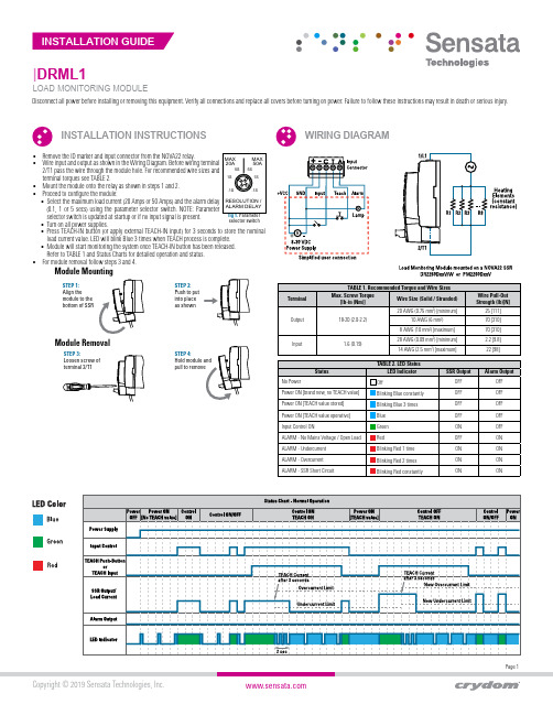
Page 1Copyright © 2019 Sensata Technologies, Inc.|DRML1LOAD MONITORING MODULEINSTALLATION INSTRUCTIONSWIRING DIAGRAMDisconnect all power before installing or removing this equipment. Verify all connections and replace all covers before turning on power. Failure to follow these instructions may result in death or serious injury.• Remove the ID marker and input connector from the NOVA22 relay.•Wire input and output as shown in the Wiring Diagram. Before wiring terminal 2/T1 pass the wire through the module hole. For recommended wire sizes andterminal torques see TABLE 2.• Mount the module onto the relay as shown in steps 1 and 2.• Proceed to configure the module:• Select the maximum load current (20 Amps or 50 Amps) and the alarm delay (0.1, 1 or 5 secs) using the parameter selector switch. NOTE: P arameter selector switch is updated at startup or if no input signal is present.• Turn on all power supplies.• Press TEACH-IN button (or apply external TEACH-IN input) for 3 seconds to store the nominal load current value. LED will blink Blue 3 times when TEACH process is complete.• Module will start monitoring the system once TEACH-IN button has been released. Refer to TABLE 1 and Status Charts for detailed operation and status.• For module removal follow steps 3 and 4.fig 1. Parameter selector switchMAX 20AMAX50A RESOLUTION /ALARM DELAY5S1S.1S 5S 1S.1S Module RemovalSTEP 1:Align the module to the bottom of SSRSTEP 4:STEP 3:Loosen screw ofterminal 2/T1Specification No.: Rev. 11/12/18Americas+1 (877) 502 5500************************Europe, Middle East & Africa +44 (1202) 416170***********************Asia Pacific*************************.com China +86 (21) 2306 1500Japan +81 (45) 277 7117Korea +82 (31) 601 2004India +91 (80) 67920890Rest of Asia +886 (2) 27602006 ext 2808Page 2CONTACT USCopyright © 2019 Sensata Technologies, Inc.Sensata Technologies, Inc. (“Sensata”) data sheets are solely intended to assist designers (“Buyers”) who are developing systems that incorporate Sensata products (also referred to herein as “components”). Buyer understands and agrees that Buyer remains responsible for using its independent analysis, evaluation and judgment in designing Buyer’s systems and products. Sensata data sheets have been created using standard laboratory conditions and engineeringpractices. Sensata has not conducted any testing other than that specifically described in the published documentation for a particular data sheet. Sensata may make corrections, enhancements, improvements and other changes to its data sheets or components without notice.Buyers are authorized to use Sensata data sheets with the Sensata component(s) identified in each particular data sheet. HOWEVER, NO OTHER LICENSE, EXPRESS OR IMPLIED, BY ESTOPPEL OR OTHERWISE TO ANY OTHER SENSATA INTELLECTUAL PROPERTY RIGHT, ANDNO LICENSE TO ANY THIRD PARTY TECHNOLOGY OR INTELLECTUAL PROPERTY RIGHT, IS GRANTED HEREIN. SENSATA DATA SHEETS ARE PROVIDED “AS IS”. SENSATA MAKES NO WARRANTIES OR REPRESENTATIONS WITH REGARD TO THE DATA SHEETS OR USE OF THE DATA SHEETS, EXPRESS, IMPLIED OR STATUTORY, INCLUDING ACCURACY OR COMPLETENESS. SENSATA DISCLAIMS ANY WARRANTY OF TITLE AND ANY IMPLIED WARRANTIES OF MERCHANTABILITY, FITNESS FOR A PARTICULAR PURPOSE, QUIET ENJOYMENT, QUIET POSSESSION, AND NON-INFRINGEMENT OF ANY THIRD PARTY INTELLECTUAL PROPERTY RIGHTS WITH REGARD TO SENSATA DATA SHEETS OR USE THEREOF.All products are sold subject to Sensata’s terms and conditions of sale supplied at SENSATA ASSUMES NO LIABILITY FOR APPLICATIONS ASSISTANCE OR THE DESIGN OF BUYERS’ PRODUCTS. BUYER ACKNOWLEDGES AND AGREES THAT IT IS SOLELY RESPONSIBLE FOR COMPLIANCE WITH ALL LEGAL, REGULATORY AND SAFETY-RELATED REQUIREMENTS CONCERNING ITS PRODUCTS, AND ANY USE OF SENSATA COMPONENTS IN ITS APPLICATIONS, NOTWITHSTANDING ANY APPLICATIONS-RELATED INFORMATION OR SUPPORT THAT MAY BE PROVIDED BY SENSATA.Mailing Address: Sensata Technologies, Inc., 529 Pleasant Street, Attleboro, MA 02703, USA.。
Modicon M221 TM221C16T 产品数据手册说明书

Modicon M221 Logic controller 24 V DC 9 discrete input conforming to IEC 61131-2 Type 1 including 4 fast input 2 at input range: 0...10 V Transistor 7 transistor including 2 fast output 24 V DC 0.5 A
0 ms for input 12 ms for input 3 ms for input
Positive logic (source)
3.5 A
100 kHz for fast output (PWM/PLS mode) at Q0...Q1 termnal 5 kHz for output at Q2...Q3 termnal 0.1 kHz for output at Q4...Q6 termnal
4 fast input (HSC mode) (counting frequency: 100 kHz), counting capacity: 32 bits
A/B Pulse/direction Single phase
USB port with connector mini B USB 2.0 Non isolated serial link "serial 1" with connector RJ45 and interface RS485 Non isolated serial link "serial 2" with connector RJ45 and interface RS232/RS485
1ZM M.2 模块 - 数据手册说明书
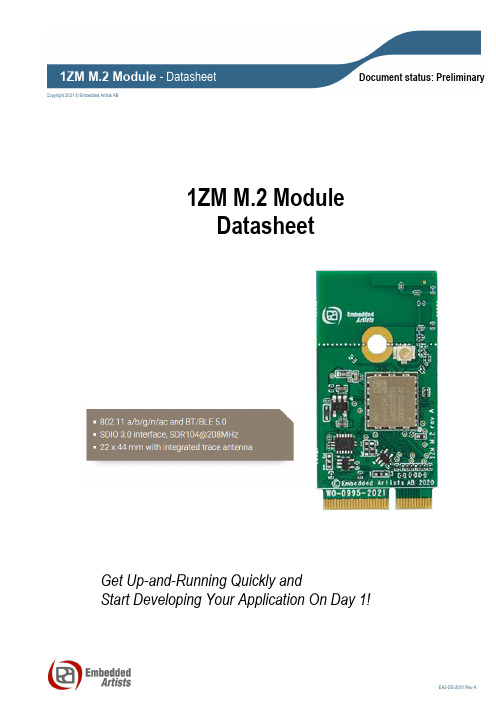
Copyright 2021 © Embedded Artists ABDocument status: Preliminary1ZM M.2 ModuleDatasheetGet Up-and-Running Quickly andStart Developing Your Application On Day 1!Embedded Artists ABJörgen Ankersgatan 12211 45 MalmöSwedenhttps://Copyright 2021 © Embedded Artists AB. All rights reserved.No part of this publication may be reproduced, transmitted, transcribed, stored in a retrieval system, or translated into any language or computer language, in any form or by any means, electronic, mechanical, magnetic, optical, chemical, manual or otherwise, without the prior written permission of Embedded Artists AB.DisclaimerEmbedded Artists AB makes no representation or warranties with respect to the contents hereof and specifically disclaim any implied warranties or merchantability or fitness for any particular purpose. The information has been carefully checked and is believed to be accurate, however, no responsibility is assumed for inaccuracies.Information in this publication is subject to change without notice and does not represent a commitment on the part of Embedded Artists AB.FeedbackWe appreciate any feedback you may have for improvements on this document.TrademarksAll brand and product names mentioned herein are trademarks, services marks, registered trademarks, or registered service marks of their respective owners and should be treated as such.Table of Contents1Document Revision History4 2Introduction5 2.1Benefits of Using an M.2 Module to get Wi-Fi/BT Connectivity5 2.2More M.2 Related Information5 2.3ESD Precaution and Handling5 2.4Product Compliance5 3Specification6 3.1Power Up Sequence7 3.2Mechanical Dimensions7 3.3M.2 Pinning9 3.4Test Points12 3.5VDDIO Override Feature Does Not Exists12 4Antenna13 4.1Mounting and Clearance13 4.2Overriding PCB Trace Antenna14 4.3Current Consumption Measurements15 4.4On-board Trace Antenna Performance16 4.4.11ZM M.2 Module Mounted on iMX OEM Carrier Board 17 4.4.21ZM M.2 Module Mounted on COM Carrier Board 21 5Regulatory24 6Disclaimers25 6.1Definition of Document Status261 Document Revision History2 IntroductionThis document is a datasheet that specifies and describes the 1ZM M.2 module mainly from a hardware point of view. Software related issues, like the Linux and WICED drivers, are not addressed. There are separate documents for that.2.1 Benefits of Using an M.2 Module to get Wi-Fi/BT ConnectivityThere are several benefit to use an M.2 module to add connectivity to an embedded design:∙Drop-in, certified solution!∙Modular and flexible approach to evaluate different Wi-Fi/BT solutions - with different trade-offs around performance, cost, power consumption, longevity, etc.∙Access to maintained software drivers (Linux and WICED) with responsive support from Murata.∙Supported by Embedded Artists' Developer's Kits for i.MX RT/6/7/8 development, including advanced debugging support on carrier boards∙One component to buy, instead of 50+∙No RF expertise is required∙Developed in close collaboration with Murata and NXP∙M.2 pinning defined in close cooperation with Murata, NXP, Cypress+Infineon and Embedded Artists2.2 More M.2 Related InformationFor more information about the M.2 standard and Embedded Artists' adaptation, see: M.2 PrimerFor more general information about the M.2 standard, see: https:///wiki/M.2The official M.2 specification (PCI Express M.2 Specification) is available from: 2.3 ESD Precaution and HandlingPlease note that the M.2 module come without any case/box and allcomponents are exposed for finger touches – and therefore extra attention mustbe paid to ESD (electrostatic discharge) precaution, for example use of static-free workstation and grounding strap. Only qualified personnel shall handle theproduct.Make it a habit always to first touch the mounting hole (which is grounded)for a few seconds with both hands before touching any other parts of theboards. That way, you will have the same potential as the board and therefore minimize the risk for ESD.In general touch as little as possible on the boards in order to minimize the risk of ESD damage. The only reasons to touch the board are when mounting/unmounting it on a carrier board.Note that Embedded Artists does not replace modules that have been damaged by ESD.2.4 Product ComplianceVisit Embedded Artists' website at /product_compliance for up to date information about product compliances such as CE, RoHS2/3, Conflict Minerals, REACH, etc.3 SpecificationThis chapter lists some of the more important characteristics of the M.2 module, but it is not a full specification of performance and timing. The main component in the design is Murata's 1ZM module (full part number: LBEE5QD1ZM), which in turn is based around NXP/Marvell 88W8987 chipset. For a full specification, see on Murata's 1MW Module (LBEE5QD1ZM) see Murata’s 1ZM product page (url TBD) and the 1ZM datasheet (url TBD).3.1 Power Up SequenceThe supply voltage shall not rise (10 - 90%) faster than 40 microseconds and not slower than 100 milliseconds.Signals WL_REG_ON must be held low for at least 1 milliseconds after supply voltage has reached specification level before pulled high.External Sleep ClockThe sleep clock signals can be applied to a powered and unpowered M.2 module.3.2 Mechanical DimensionsThe M.2 module is of type: 2230-S3-E according to the M.2 nomenclature. This means width 22 mm, length 30mm (without trace antenna), top side component height 1.5 mm and key-E connector. The table below lists the different dimensions and weight.Embedded Artists has added a non-standard feature to the 2230 M.2 modules designed together with Murata. The pictures below illustrates the how the standard module size has been extended by 14 mm in the length direction in order to include a pcb trace antenna.Figure 1 – M.2 Module with, and without, PCB Trace AntennaThe picture below gives dimensions for the grounded center (half) hole and the u.fl. antenna connector.Figure 2 – M.2 Module, Antenna Connector Position22 mm30 m m44 m m22 mm1.5 mm11 mm,3.3 M.2 PinningThis section presents the pinning used for the M.2 module. It is M.2 Key-E compliant. The pin assignment for specific control and debug signals has been jointly defined by Embedded Artists, Murata, NXP and Infineon/Cypress.The picture below illustrates the edge pin numbering. It starts on the right edge and alternates between top and bottom side. The removed pads in the keying notch counts (but as obviously non-existing).Figure 3 – M.2 Module Pin NumberingThe Wi-Fi interface uses the SDIO interface. The Bluetooth interface uses the UART interface forcontrol and PCM interface for audio. The table below lists the pin usage for the 1ZM M.2 modules. The column "When is signal needed" signals four different categories:∙ Always: These signals shall always be connected.∙ Wi-Fi: These signals shall always be connected then the Wi-Fi interface is used.∙ Bluetooth: These signals shall always be connected then the Bluetooth interface is used. ∙ Optional: These signals are optional to connect.3.4 Test PointsThere are some test points that can be of interest to probe for debugging purposes, as illustrated in the picture below.Figure 4 – 1ZM M.2 Module Test Points3.5 VDDIO Override Feature Does Not ExistsThe M.2 standard specify 1.8V logic level on several of the data and control signals. Other M.2 modules in the Embedded Artists' family supports VDDIO override to 3.3V instead.Note that the 1ZM M.2 module does not support this feature because of limitations in the NXP88W8987 chipset. The control signals that are 1.8V according to the M.2 standard must be 1.8V. This is also true for the SDIO voltage level. It must be 1.8V.4 AntennaThis chapter address the antenna side of the module. There is an on-board, reference certified pcb trace antenna. This can be used for testing/evaluation purposes, but also for the final product. Also, for testing and evaluation purposes, it is possible to disconnect the on-board antenna and instead use an u.fl. connector to connect an external antenna.4.1 Mounting and ClearanceIdeally, arrange the M.2 module so that the antenna is located at a corner of the product. Keep plastic case (i.e., non-metallic) away from the antenna area with at least 5 mm clearance (in all directions). Also keep any metal elements (e.g., connectors, battery, etc.) away from the antenna area with at least 5 mm clearance (in all directions). Keep a clearance area under and above the antenna area of at least 7.5mm , both under and over the PCB.Human hands or body parts should be kept away (in the normal use case) from the antenna area. The ground hole in the middle shall be grounded. Use a metal stand-off according to M.2 standard (height suitable for selected M.2 connector) and use metal screw to create a proper ground connection.Figure 5 – M.2 Module Clearance Area4.2 Overriding PCB Trace AntennaThe antenna connection from the 1ZM module be redirected to the u.fl. connector by just moving one zero ohm 0201 series resistor, see illustration below. The on-board trace antenna can be left as-is, or the antenna can be snapped-off.Figure 6 – Rework to Connect U.FL. ConnectorSnap-off on-board antenna, if needed, else just leave as-is.4.3 Current Consumption MeasurementsIt is possible to measure the currents of the power supplies to the 1YM module, VBAT and VIO. VBAT is the 3.3V the is supplied to the M.2 interface and VIO is an on-board generated 1.8V. VIO isgenerated from the supplied 3.3V. If the supply voltage (3.3V) to the M.2 module is measured it will be both the VBAT and VIO currents that is measured. By measuring currents at the illustrated points blow it is possible to measure VBAT and VIO independently.Note that zero ohm resistors are mounted by default. Select a series resistor with as low resistance as possible to keep the voltage drop to a minimum. Keep the drop below 100mV. VBAT can be slightly above 1 Amp in peak which means that maximum series resistance is 100 milliOhm for the VBAT resistor.Figure 7 – Current Measurement4.4 On-board Trace Antenna PerformanceThe on-board pcb trace antenna type is monopole. The 1ZM M.2 module has been measured both standalone and mounted on the iMX OEM Carrier Board (which is a typical carrier board design). The table below lists total efficiency:The table below lists peak gain:4.4.1 1ZM M.2 Module Mounted on iMX OEM Carrier BoardThe 3D directivity measurements are presented below for the 2 GHz and 5GHz bands when the 1ZM M.2 module is mounted on the iMX OEM Carrier Board.Figure 8 – 3D Directivity Measurements in 2 GHz BandFigure 9 – 3D Directivity Measurements in 5 GHz BandFigure 10 – 3D Directivity Measurements Plane OrientationsThe pictures below illustrates the return loss, efficiency and directivity when the 1ZM M.2 module ismounted on the iMX OEM Carrier Board.Figure 11 – Return Loss for 1ZM M.2 Module Mounted on iMX OEM Carrier BoardFigure 12 – Efficiency for 1ZM M.2 Module Mounted on iMX OEM Carrier BoardFigure 13 – Directivity for 1ZM M.2 Module Mounted on iMX OEM Carrier Board4.4.2 1ZM M.2 Module Mounted on COM Carrier BoardThe 3D directivity measurements are presented below for the 2 GHz and 5GHz bands when the 1ZM M.2 module is mounted on the COM Carrier Board.Figure 14 – 3D Directivity Measurements in 2 GHz BandFigure 15 – 3D Directivity Measurements in 5 GHz BandThe pictures below illustrates the return loss, efficiency and directivity when the 1ZM M.2 module is mounted on the COM Carrier Board.Figure 16 – Return Loss for 1ZM M.2 Module Mounted on COM Carrier BoardFigure 17 – Efficiency for 1ZM M.2 Module Mounted on COM Carrier BoardFigure 18 – Directivity for 1ZM M.2 Module Mounted on COM Carrier Board5 Regulatory <TBC>6 DisclaimersEmbedded Artists reserves the right to make changes to information published in this document, including, without limitation, specifications and product descriptions, at any time and without notice. This document supersedes and replaces all information supplied prior to the publication hereof. Customer is responsible for the design and operation of their applications and products using Embedded Artists’ products, and Embedded Artists accepts no liability for any assistance with applications or customer prod uct design. It is customer’s sole responsibility to determine whether the Embedded Artists’ product is suitable and fit for the customer’s applications and products planned, as well as for the planned application and use of customer’s third party customer(s). Customers should provide appropriate design and operating safeguards to minimize the risks associated with their applications and products. Customer is required to have expertise in electrical engineering and computer engineering for the installation a nd use of Embedded Artists’ products.Embedded Artists does not accept any liability related to any default, damage, costs or problem which is based on any weakness or default in the customer’s applications or products, or the application or use by custome r’s third party customer(s). Customer is responsible for doing all necessary testing for the customer’s applications and products using Embedded Artists’ products in order to avoid a default of the applications and the products or of the application or use by customer’s third party customer(s). Embedded Artists does not accept any liability in this respect.Embedded Artists does not accept any liability for errata on individual components. Customer is responsible to make sure all errata published by the manufacturer of each component are taken note of. The manufacturer's advice should be followed.Embedded Artists does not accept any liability and no warranty is given for any unexpected software behavior due to deficient components.Customer is required to take note of manufacturer's specification of used components. Such specifications, if applicable, contains additional information that must be taken note of for the safe and reliable operation.All Embedded Artists’ products are sold pursuant to Embedded Artists’ terms and conditions of sale: /sites/default/files/docs/General_Terms_and_Conditions.pdfNo license, express or implied, by estoppel or otherwise, to any intellectual property rights is granted under this document. If any part of this document refers to any third party products or services it shall not be deemed a license grant by Embedded Artists for the use of such third party products or services, or any intellectual property contained therein or considered as a warranty covering the use in any manner whatsoever of such third party products or services or any intellectual property contained therein.UNLESS OTHERWISE SET FORTH IN EMBEDDED ARTISTS’ TERMS AND CONDITIONS OF SALE EMBEDDED ARTISTS DISCLAIMS ANY EXPRESS OR IMPLIED WARRANTY WITH RESPECT TO THE USE AND/OR SALE OF EMBEDDED ARTISTS PRODUCTS INCLUDING WITHOUT LIMITATION IMPLIED WARRANTIES OF MERCHANTABILITY, FITNESS FOR A PARTICULAR PURPOSE (AND THEIR EQUIVALENTS UNDER THE LAWS OF ANY JURISDICTION), OR INFRINGEMENT OF ANY PATENT, COPYRIGHT OR OTHER INTELLECTUAL PROPERTY RIGHT. UNLESS EXPRESSLY APPROVED IN WRITING BY THE CEO OF EMBEDDED ARTISTS, PRODUCTS ARE NOT RECOMMENDED, AUTHORIZED OR WARRANTED FOR USE IN MILITARY, AIR CRAFT, SPACE, NUCLEAR, LIFE SAVING, OR LIFE SUSTAINING APPLICATIONS, NOR IN PRODUCTS OR SYSTEMS WHERE FAILURE OR MALFUNCTION MAY RESULT IN PERSONAL INJURY, DEATH, OR SEVERE PROPERTY OR ENVIRONMENTAL DAMAGE.Resale of Embedded Artists’ products with provisions different from the statements and/or tec hnical features set forth in this document shall immediately void any warranty granted by Embedded Artistsfor the Embedded Artists’ product or service described herein and shall not create or extend in any manner whatsoever, any liability of Embedded Artists.This document as well as the item(s) described herein may be subject to export control regulations. Export might require a prior authorization from national authorities.6.1 Definition of Document StatusPreliminary– The document is a draft version only. The content is still under internal review and subject to formal approval, which may result in modifications or additions. Embedded Artists does not give any representations or warranties as to the accuracy or completeness of information included herein and shall have no liability for the consequences of use of such information. The document is in this state until the product has passed Embedded Artists product qualification tests.Approved– The information and data provided define the specification of the product as agreed between Embedded Artists and its customer, unless Embedded Artists and customer have explicitly agreed otherwise in writing.。
tmc2210中文规格书

tmc2210中文规格书TMC2210中文规格书一、产品介绍TMC2210是一款先进的步进电机驱动器,具有高性能和高精度的特点。
该驱动器采用了最新的技术,为用户提供了更好的驱动体验。
TMC2210适用于各种领域,如工业自动化、机器人、3D打印等。
二、主要特点1. 高精度:TMC2210采用了先进的运动控制算法,能够实现高精度的步进电机驱动,确保运动的平稳和准确性。
2. 低噪音:该驱动器通过改进的电流控制和电机驱动技术,降低了噪音水平,提供了更加安静的工作环境。
3. 高效能:TMC2210的电源效率非常高,能够最大程度地利用电能,减少能源浪费。
4. 多种保护功能:该驱动器具有过流保护、过温保护、欠压保护等多种保护功能,可以有效保护电机和驱动器的安全运行。
5. 简化设计:TMC2210的设计紧凑,可以方便地集成到各种设备中,简化了系统的设计和安装。
三、技术参数1. 电源电压范围:5V-28V2. 驱动电流:最大2.5A3. 步进角度:1.8°4. 步进分辨率:最大256微步5. 控制接口:SPI、UART6. 工作温度范围:-40°C至+85°C7. 封装形式:QFN48四、应用领域TMC2210广泛应用于各种领域,包括:1. 工业自动化:TMC2210可以用于控制各种工业设备,如数控机床、印刷机、包装机等。
2. 机器人:该驱动器可以用于机器人的关节控制,提供高精度和高效能的驱动能力。
3. 3D打印:TMC2210可以用于3D打印机的各个轴的驱动,实现高精度和高速度的打印。
五、总结TMC2210是一款高性能的步进电机驱动器,具有高精度、低噪音和高效能的特点。
该驱动器适用于工业自动化、机器人和3D打印等领域。
它的多种保护功能和简化设计使其成为用户的首选。
希望通过本规格书的介绍,能够使用户更好地了解TMC2210的特点和应用。
Omega 22 mm OMPBD7 推按钮和选择开关系列产品说明书

22 mm PILOT DEVICES OMPBD7 SERIESPUSHBUTTONS AND SELECTOR SWITCHESOmegas rugged OMPBD7 pilot devices offer maximum flexibility and a wide choice for all applications. This 22 mm line is aesthetically appealing and modularly designed to make assembly and interchangeability easy. The OMPBD7 operators are available in two different body styles to meet every application need. Both operators exhibit a new lower profile stylish appearance while maintaining the rugged performance necessary for demanding environments.Two Operator TypesOMPBD7P is a plastic operator with acaptive black plastic front bezel. Constructed of high-grade thermoplastics, the OMPBD7P is the corrosion resistant solution for harsh environments. For super tough applications,the OMPBD7M has a die-cast zinc housing and mounting ring for a rugged durability.Both are finished with corrosion resistant chrome plating. The OMPBD7M also features a captive shiny metal bezel for a polished appearance.Quick, Easy InstallationA standard anti-rotation tab keeps front elements from turning or falling off the control panel, making it possible for one person to install all OMPBD7components even if the front and rear panel are not accessible at the same time. A central mounting ring allows for quick installation and removal of all OMPBD7 operators. All back-of-panel components including contact blocksand power module elements snap-on and are readily accessible and interchangeable without removing the pilot device from the panel.Tool-Less Mounting LatchThe OMPBD7 “tool-less” mounting latch mates the front element with the contact blocks and other back-of-panel components.The mounting latch is available in a plastic and metal design. The latches are easily installed with a “click” and removed by pushing a rotating collar to the right. Quick,reliable and strong, it’s the best pilot device mounting latch available in the industry.Long Electrical and Mechanical LifeMost OMPBD7 operators have a mechanical of ten million operations… five million contact blocks. Electrical life ranges from 500,000 cycles at 3 A to ten million at 0.1 A.The OMPBD7 line is also electronics compatible with self cleaning contacts.Environmental RatingsFront elements, including pushbuttons,mushroom operators and selector switches,are IP66 rated against submersion, oil and dirt, making them reliable in the toughest industrial environments. Metal operators are NEMA 4/13 rated and plastic operators are rated NEMA 4/4X/13.OMPBD7M-F3PX10, $24, metal pushbutton,flush button, green,momentary operation with 1 NO contact.OMPBD7P-E4PX10, $24, plastic pushbutton,extended button, red,momentary operation with 1 NO contact.OMPBD7P-MT34PX01, $45,plastic pushbutton, 30 mm mushroom, red, maintained operation with 1 NC contact.Each pushbutton includes one contact block. Units shown with two additionalblocks (pushbuttons may be used with up to 6 contacts)see page I-26.l Heavy-Duty/Oil Tight Pushbuttonsl Quick Installation with Tool-Less Mounting Latchl Plastic Operators: NEMA 4/4X/13and IP65/66 Ratedl Metal Operators: NEMA 4/13 and IP65/66 Ratedl Touch-Safe ContactBlocks–with IP20 Recessed Screw Terminalsl Heavy-Duty Current Rating(10A Continuous)All models shownlarger than actual size.Additional Featuresand OptionsHeavy-Duty Ratings—The OMPBD7 lineis UL 46E, NEMA A600 and Q600 listed. All components carry a 10 Amp continuous current rating, covering all industrial control needs.All Major Approvals—OMPBD7 front elements are UL Recognized, while all OMPBD7 assemblies are UL Approved. The line is also approved by every major international agency making themideal for export requirements.H-Bridge & Gold Plated Contacts—By doubling the available paths for current to pass through the contacts, the standard H-bridge design provides a cleaner current flow. Gold plated contacts quadruple the current paths for increased contact reliability in low voltage applications.Touch-Safe—Back of panel components are finger safe, with IP20 protection.Long Lasting Integral LED Assemblies—Our new LED lamps last up to 11 years! They are conveniently offered as a complete unit for all illuminated operators which include the one piece Integral LED Module. They come in five different colors: amber, blue, green, red and white.OMPBD7M-HM22PX01, two way metal selector switch with long knob.Each unit includes tool-less mounting latch and one normally closed contact block.Shown with two additional (up to 6 total per operator possible) normally opencontact blocks, model OMPBD7-X10, $8.50 each.All shown largerthan actual size.CONTACT BLOCKSRed = normally closed.OMPBD7-X01, $8.50.OMPBD7-X10, $8.50.Green = normally open.Rear view.OMPBD7P-LMM43PX10, $39, plastic pushbutton,green, 40 mm mushroom,momentary operation, one NO contact, shown larger than actual size.OMPBD7P-LE4PX01, $30, plastic pushbutton, extended button, red, momentary operation, one NC contact,shown larger than actual size.22 mm PUSHBUTTONSILLUMINATED PUSHBUTTONS AND E-STOPSOMPBD7-IL Series Start at$51(Specify Model Number)MOST POPULAR MODELS HIGHLIGHTED!used per operator (light module occupies center position).*Insert number for color selection, 2= black, 3= green, 4= red, 5= yellow, 6= blue.Complete with pushbutton and light moduleEach operator includestool-less mounting latch and one contact block. Shown with two additional (up to 4total per operator possible)contact blocks.used per operator.Front-of-Panel (Operators)1Notes:1Performance data given in this publication is provided only as a guide for the user in determining suitability and do not constitute a performance warranty of any kind. Such data may represent the results of accelerated testing at elevated stress levels, and the user is responsible for correlating the data to actual application requirements. ALL WARRANTIES AS TO ACTUAL PERFORMANCE, WHETHER EXPRESS OR IMPLIED, ARE EXPRESSLY DISCLAIMED.2Momentary mushroom operators are IP65, multi-function operators are not Type 13 rated. Plastic operators with keys are not Type 4X rated.3Operating temperatures below 0°C (32°F) are based on the absence of freezing moisture and liquids, UL recognized to 55°C (131°F)incandescent module, max 40°C (104°F).22 mm PILOT DEVICESHEAVY-DUTY/OIL TIGHT PUSHBUTTONSAND SELECTOR SWITCHES OMPBD7 SERIESNon-illuminated pushbuttons, shown on pages I-25 and I-26.Notes:1Performance data given in this publication is provided only as a guide for the user in determining suitability and do not constitute a performance warranty of any kind. Such data may represent the results of accelerated testing at elevated stress levels, and the user is responsible for correlating the data to actual application requirements. ALL WARRANTIES AS TO ACTUAL PERFORMANCE, WHETHER EXPRESS OR IMPLIED, ARE EXPRESSLY DISCLAIMED.4Low voltage contacts are recommended for applications below 17 V, 5 mA.5Wires less than #18 (0.75 mm2) may not hold in terminal securely.CANADA www.omega.ca Laval(Quebec) 1-800-TC-OMEGA UNITED KINGDOM www. Manchester, England0800-488-488GERMANY www.omega.deDeckenpfronn, Germany************FRANCE www.omega.fr Guyancourt, France088-466-342BENELUX www.omega.nl Amstelveen, NL 0800-099-33-44UNITED STATES 1-800-TC-OMEGA Stamford, CT.CZECH REPUBLIC www.omegaeng.cz Karviná, Czech Republic596-311-899TemperatureCalibrators, Connectors, General Test and MeasurementInstruments, Glass Bulb Thermometers, Handheld Instruments for Temperature Measurement, Ice Point References,Indicating Labels, Crayons, Cements and Lacquers, Infrared Temperature Measurement Instruments, Recorders Relative Humidity Measurement Instruments, RTD Probes, Elements and Assemblies, Temperature & Process Meters, Timers and Counters, Temperature and Process Controllers and Power Switching Devices, Thermistor Elements, Probes andAssemblies,Thermocouples Thermowells and Head and Well Assemblies, Transmitters, WirePressure, Strain and ForceDisplacement Transducers, Dynamic Measurement Force Sensors, Instrumentation for Pressure and Strain Measurements, Load Cells, Pressure Gauges, PressureReference Section, Pressure Switches, Pressure Transducers, Proximity Transducers, Regulators,Strain Gages, Torque Transducers, ValvespH and ConductivityConductivity Instrumentation, Dissolved OxygenInstrumentation, Environmental Instrumentation, pH Electrodes and Instruments, Water and Soil Analysis InstrumentationHeatersBand Heaters, Cartridge Heaters, Circulation Heaters, Comfort Heaters, Controllers, Meters and SwitchingDevices, Flexible Heaters, General Test and Measurement Instruments, Heater Hook-up Wire, Heating Cable Systems, Immersion Heaters, Process Air and Duct, Heaters, Radiant Heaters, Strip Heaters, Tubular HeatersFlow and LevelAir Velocity Indicators, Doppler Flowmeters, LevelMeasurement, Magnetic Flowmeters, Mass Flowmeters,Pitot Tubes, Pumps, Rotameters, Turbine and Paddle Wheel Flowmeters, Ultrasonic Flowmeters, Valves, Variable Area Flowmeters, Vortex Shedding FlowmetersData AcquisitionAuto-Dialers and Alarm Monitoring Systems, Communication Products and Converters, Data Acquisition and Analysis Software, Data LoggersPlug-in Cards, Signal Conditioners, USB, RS232, RS485 and Parallel Port Data Acquisition Systems, Wireless Transmitters and Receivers。
TM-xa系列 计重型 收银系列使用说明书V2.30B
1.4 规格 ................................................................................................................. 6 1.5 TM-xA 系列热敏打印机 .................................................................................. 6
前言
感谢您使用上海精函有限公司的产品!在您开始使用本产品前,请务必仔细阅读《前言》中的内容, 并严格遵守这些事项!
1.1 注意事项
Ø 确保电源插头和电源线连接正常,使用三芯电源线进行连接,如果使用了拖线板,则拖线板的插口 也要是三芯的,确保三芯的地线妥善的与建筑大地连接,以避免漏电的情况。
Ø 切勿用沾湿的手插拔电源插头,这样可能导致触电。 Ø 严禁将身体重力压在秤盘上,以免损坏称重传感器。 Ø 严禁撞击重压,或用重物冲击秤盘,以免损坏称重传感器,同时勿超过其最大称量范围。 Ø 严禁淋雨或用水冲洗;如不慎沾水,请用干布擦试干净;若秤体工作异常,请尽速送到经销商处,
- 1、下载文档前请自行甄别文档内容的完整性,平台不提供额外的编辑、内容补充、找答案等附加服务。
- 2、"仅部分预览"的文档,不可在线预览部分如存在完整性等问题,可反馈申请退款(可完整预览的文档不适用该条件!)。
- 3、如文档侵犯您的权益,请联系客服反馈,我们会尽快为您处理(人工客服工作时间:9:00-18:30)。
0X16
命令名
参数 1
参数 2
校验
注:校验 = (命令名+参数 1+参数 2) MOD 256
2
广州市钛码电子科技有限公司
表 3 命令名及含义
代码
参 1
0xF1
0x00
0xF2
0x00
0xF3
0x00
0XF4
0x01:标准休眠(默认) 0x02:深度休眠
参数 2 0x00 0x00 0x00
0x00
3.9厘米×2.8 厘米×1.8 厘米 注:“休眠”和“深度休眠”的区别在于恢复到工作状态的时间不同。休眠恢复到工作状态的时间小 于 1 毫秒。深度休眠恢复到工作状态的时间约为 100 毫秒。
1
三、TM22XX 模块使用说明
广州市钛码电子科技有限公司
/
表 2 扫描器引脚定义
可驱动 3.3V 无源蜂鸣器 低:没有读取到条码,或者条码数据已 经发送完成(LED 灭)。 高:已经完成条码读取(LED 亮)。 低:省电状态;高:正常工作 低:待机状态;高:读码状态。
扫描模式 TM22XX 系列扫描器有两种工作模式: 手动模式 为默认的工作模式。在这种模式下,TRIG 引脚输入高电平,扫描器处于读码状态。读码成功
2.性能稳定 模块的软件和硬件都经过精心设计和严格测试,具有稳定的性能,适合长时间连续工作。
3.丰富的条码码制 模块支持所有常见的一维码,并可根据用户的需求添加自定义码制。
4.接口简单,使用方便 模块以RS232的形式输出条码数据。在RS232设置成无握手协议的情况下,用户只需要接两根电源线(GND
自动扫描模式(连续扫描模式)
RS-232 接口参数设置
波特率:
2400 4800 9600(默认) 19200
握手协议: 无握手协议:阅读器只使用 RXD 和 TXD 两个数据线进行通信,并且在有数据需要传输的时候,直接按
约定的格式发给对方,而不进行任何形式(包括软件或者硬件的方式)应答。这是本设备的默认工作方式。 无握手协议*(默认)
广州市钛码电子科技有限公司
钛码 TM22XX 系列模块说明书
/
一.TM22XX系列一维条码阅读模块特性:
1.内置解码器 模块内置32位解码器,解码完成后直接输出条码数据的ASCII码,因此用户无需编写条码解码程序,有
助于缩短您的产品的开发周期。
2.解码能力强 采用自主研发的解码软件,解码能力强,能解超长、弯曲或者磨损的条码。
该模式只适用于 TM2240。 当扫描器进入省电状态,扫描器的功耗将降至最低(根据不同设定,电流为 12mA 或小于 1 毫安)。处 于省电状态,扫描器不读条码。 进入省电状态,只需把 PWD 引脚拉低,扫描器将在 60mS 内进入省电状态。退出省电状态只需把 PWD 引 脚重新拉高即可。扫描器将在 60mS 内恢复到待机模式。 工作状态指示 如果扫描器成功读取到一个条码,则 LED 输出一个高电平,并在串口数据传输完成后,恢复低电平。 LED 引脚如果外接发光二极管,则必须串一个 1K 的限流电阻。 在 LED 输出高电平的同时,BEEPER 输出一个频率约为 2.5KHz 的波形(频率可调),用于驱动 3.3V 的 无源蜂鸣器。 软件命令 主机可以通过串口命令来控制扫描器。命令的格式为:
码,93 码,11 码,MSI/Plessey,UCC/EAN 128,中国邮政码,GS1
DataBar(是最新的国际标准条码,前身是RSS)系列
提示方式 外接蜂鸣器和LED 指示灯 数据接口 RS-232 串口(3.3V电平) 触发方式 外部脉冲触发/串口命令触发/条码靠近自动扫描 尺 寸 宽×长×高:
/ 4
3
广州市钛码电子科技有限公司
标准的 RTS/CTS:阅读器和主机的握手协议以标准的形式进行。 标准 RTS/CTS
RTS 有效电平设置
Host:Low RTS *(默认)
数据位数:
7位 8 位(默认)
停止位:
1 位(默认) 2位
校验方式
无校验(默认) 奇校验 偶校验
标志校验(MART) 空(SPACE)
序号 名称
类型
1
UPDATA
输入,内部下拉
2
VCC
输入
3
GND
输入
4
RXD
输入
5
TXD
输出
6
CTS
输入
7
RTS
输出
8
NC
9
BEEPER
输出,漏极开路
10 LED
输出
11 PWD 12 TRIG
输入,内部上拉 输入,内部下拉
备注 低: 正常工作;高:进入固件升级模式 电源 3.3V 接地 串行数据输入 串行数据输出 允许数据发送 请求数据发送
和VCC)和一根串口数据线(TXD)即可以获取条码数据,非常适合各种嵌入式系统和自动控制系统使用。
二 、TM22XX 模块技术指标及参数
表 1 扫描器技术指标及参数
电源电压 直流3.3V
工作:42 毫安;
读码瞬间:75毫安; 电源电流
休眠:12毫安;
深度休眠:<1毫安 (深度休眠时,扫描电路关闭)
CPU
32位解码器
光 源 可视激光二极管,波长655 纳米
解码速度 100 次/秒
解 析 度 0.08 毫米(3mil)高解析度系列,或0.1 毫米(4mil)长景深系列
支持码制 UPC-A,UPC-E,EAN-13,EAN-8,ISBN/ISSN,39 码,39 码(ASCII
全码),32码,交叉25 码,工业25 码,矩阵25 码,库德巴码,128
请扫描以下设置条码,以设置相关参数: 选择 RS232 接口有效
/
功能 开始扫描 进入手动扫描模式 进入自动扫描模式 睡眠模式设定
手动模式:按下按键,阅读器发射激光并开始解码。完成解码后,阅读器自动关闭激光,并发出提示信号。 手动扫描模式(默认)
连续扫描模式下,阅读器的激光处于常亮状态。只要有可读条码进入阅读区则自动读取条码数据。但只在 当前已读条码离开之后,才可以读取下一个条码。
后,阅读器通过串口输出条码数据;如果长时间(可设置)读不到条码,则自动关闭激光,退出扫描读码 状态。
手动模式两次读取条码的时间间隔不小于 60mS。即在完成一次条码读取后,TRIG 必须至少保存 60mS 的低电平时间。
自动模式 扫描器的激光器处于常亮状态,并且在有条码进入扫描区域时自动读取。在已经读取的条码 离开扫描区后,扫描器可以继续读取下一个条码。这种模式下,条码的读取由扫描器自动完成,不受 TRIG 电平控制。 省电状态