萨牌仪表说明书 叉车资料
有关叉车说明书的内容

有关叉车说明书的内容有关叉车说明书的内容篇一:12t叉车说明书前言本说明书主要介绍重装系列12-13.5t叉车的有关性能、结构、操作和维修保养等方面内容,以便操作人员了解叉车,正确地使用和维修。
叉车在使用过程中,用户的有关操作人员和设备管理人员应认真执行本说明书上对叉车的要求和规定,使叉车经常保持良好的技术状况。
由于叉车产品不断地进行改进而作更改,本说明书内容与叉车实物有出入,恕不另行通知,敬请用户谅解。
例:–发动机及变型代号(见铭牌或合格证上出厂编号数字后代码)型号注:本说明书中的车型代号与产品铭牌和合格证上的型号不同,本车型代号包括了发动机及变型代号。
目录一、叉车驾驶、操作安全规程????2二、主要技术参数???5三、叉车的主要部件介绍6四、叉车的结构、原理、调整及维护?71. 动力系统 72. 传动装置103. 驱动桥194. 电气系统205. 制动系统296. 转向系统327. 液压系统378. 起升缸和倾斜缸??479. 起重系统51一、叉车驾驶、操作安全规程叉车驾驶人员和管理人员必须牢记―安全第一‖,按照叉车《使用维护说明书》和《司机手册》进行安全操作,规范操作。
1. 叉车的运输用汽车装运叉车时须注意如下事项:(1)刹住停车制动;(2)门架与配重前后都应用钢丝固定好;前后轮胎相应位置用楔块垫好楔牢;(3)起吊时按照叉车的―起吊标牌‖所注位置进行起吊。
2. 叉车的存放(1)放净燃油;( 冷却液是防锈防冻液,则不要放)(2)未漆件表面涂以防锈油,起升链条涂润滑油;(3)门架降到最低位置;(4)刹住停车制动;(5)前后轮胎用楔块垫好。
3. 使用前准备(1)不要在有明火的地方检查燃油、漏油、油位以及检查电气仪表,不要在运转时加燃油;(2)检查轮胎气压;(3)前进、倒退档手柄应在中间位置(零档位置);(4)在燃油系统工作及检查电瓶时不要吸烟;(5)检查各手柄及踏板情况;(6)作好起动前准备工作;(7)松开停车制动;(8)进行门架升降、前后倾、转向、制动的试动作。
萨牌双交流电控DUALAC2说明书
目录1 简介2 规范2.1D U A L A C2的技术规范 52.2D U A L A C2&H P的技术规范 62.3D U A L A C2P O W E R(加强型)的技术规范72.4D U A L A C2&H P P O W E R(加强型)的技术规范82.5控制单元82.5.1微动开关82.5.2加速单元82.5.3其他模拟控制单元92.5.4速度反馈92.5.5转向角传感器10 2.6保护特性11 2.7操作特性12 2.8故障诊断13 2.9热保护措施13 2.10常规问题的解决与防范13 2.11磁化与磁辐射13 2.12主接触器与应急开关14 3安全与保护14 4、安装144.1连接电缆14 4.2接触器15 4.3熔断器15 4.4“D U A L A C2”与“D U A L A C2”加强型的接线说明15 4.5“D U A L A C2”与“D U A L A C2&H P”加强型的接线说明174.6编码器安装194.7C A N B U S连接器的结构194.7.1单个D U A L A C2控制器194.7.2“D U A L A C2”作为C A N B U S网络的终端模块204.7.3“D U A L A C2”作为循环模块接入C A N B U S网络204.8电源接线图214.8.1“D U A L A C2”214.8.2“D U A L A C2加强型”224.8.3“D U A L A C2&H P”234.8.4“D U A L A C2&H P加强型”244.9机械图254.10“D U A L A C2”与“D U A L A C2加强型”标准接线图294.11“D U A L A C2&H P”与“D U A L A C2&H P加强型”标准接线图305、利用手持单元的编程及调整315.1使用手持单元调整31 5.2手持单元及连接器接线的描述315.3标准手持单元菜单的介绍32 5.3.1“D U A L A C2”与“D U A L A C2加强型”菜单结构325.3.1a主菜单325.3.1b从菜单335.3.2“D U A L A C2&H P”与“D U A L A C2&H P加强型”菜单设置345.3.2a主菜单345.3.2b从菜单355.4功能设置35 5.4.1“D U A L A C2”与“D U A L A C2加强型”—主控制部分35 5.4.2“D U A L A C2”与“D U A L A C2加强型”—从控制部分375.4.3“D U A L A C2&H P”与“D U A L A C2&H P加强型”—主控制部分功能38 5.4.4“D U A L A C2&H P”与“D U A L A C2&H P加强型”—从控制部分功能385.5参数调节40 5.5.1“D U A L A C2”—主控制部分40 5.5.2“D U A L A C2”—从控制部分41 5.5.3“D U A L A C2&H P”—主控制部分415.5.4“D U A L A C2&H P”—从控制部分425.6可编程的控制器的功能46 5.6.1功能设置(参见 5.4)465.6.2参数编程(参见 5.5)465.6.3“D U A L A C2&H P”与“D U A L A C2&H P加强型”测试465.6.4“D U A L A C2&H P”与“D U A L A C2&H P加强型”测试475.6.5储存功能(存储数据)—仅适用于P C控制47 5.6.6复制功能(下载参数用于其他控制)—仅适用于P C手持单元47 5.6.7显示最后5次报警信息,连同小时计值,温度一起显示47 5.6.8加速器范围整定48 5.6.9参见手持单元手册对于功能和参数的详细说明485.7A C牵引逆变器设置顺序485.8测试功能描述48 5.8.1“D U A L A C2”与“D U A L A C2加强型”—主控制部分495.8.2“D U A L A C2”与“D U A L A C2加强型”—从控制部分50 5.8.3“D U A L A C2&H P”与“D U A L A C2&H P加强型”—主控制部分515.8.4“D U A L A C2&H P”与“D U A L A C2&H P加强型”—从控制部分526、其他功能54 6.1保存与复制功能54 6.2报警菜单描述54 6.3手持单元整定加速器操作过程557、“D U A L A C2”与“D U A L A C2&H P”故障诊断56 7.1与牵引相关的错误编码56 7.2手持单元显示的关于牵引相关的报警分析60 7.3与泵斩波器相关的故障编码647.4手持单元显示的关于油泵方面的报警分析658、推荐使用部件659、定期维护67= 凡标注此记号的章节是与安全相关的内容签名表公司DEPT.设备执行经理工程执行部分出货管理员出版物编号:版本1 简介ZAPIMOS系列中的DUAL AC2逆变器适合用于3—7KW一对电机控制。
Ae0zp0ba (AC0-ing)

INDEXPage 1Introduction (3)2Specification (3)2.1Technical specifications (3)2.2Control unit (4)2.2.a Microswitches (4)2.2.b Accelerator unit (4)2.2.c Other analog control unit (5)2.2.d Speed feedback (5)2.3Protection features (6)2.4Operational features (7)2.5Diagnosis (8)2.6Thermal consideration (8)2.7General instructions and precautions (8)2.8Susceptibility and electromagnetic emission (9)2.9Main contactor and emergency switch (9)3Installation (10)3.1Connection cables (10)3.2Contactors (10)3.3Fuses (10)3.4Description of connectors - Standard version (11)3.5Description of connectors - MDI PRC Version (13)3.6Encoder installation (15)3.7Description of power connections (16)3.8Mechanical drawing (17)3.9Connection drawing - Standard Version (18)3.10Connection drawing - MDI PRC Version (19)4Programming & Adjustments using Digital Console (20)4.1Adjustments via Console (20)4.2Description of Console & Connection (20)4.3Description of Standard Console Menu (21)4.3.a Standard Version (21)4.3.b MDI PRC Version (22)4.4Function configuration (23)4.4.a Standard Version (23)4.4.b MDI PRC Version (28)4.5Parameter regulation: Standard Version (37)4.6Parameter regulation: MDI PRC Version (39)4.7Programming console functions (43)4.8Sequence for Ac Inverter Traction setting (44)4.9Tester: description of the function; Standard Version (45)4.10Tester: description of the function; MDI PRC Version (48)=The informations included into the marked paragraphs by this symbol areessential for the safety.SIGNATURES TABLE SE C I V R E S .T P E D Y N A P M O C EM V I T U C E X E T N E M E G A N A EV I T U C E X E N O I T C E S G N I R E E N I G N E R E G A N A M T R O P X E Publications N°: AE0ZP0BAEdition: October 20015Other functions............................................................................................515.1Description of the Console Save function .............................................515.2Description of Console Restore function...............................................525.3Description of Alarms menu .................................................................535.4Description of Console Program Vacc function (546)AC0 Inverter diagnostic...............................................................................556.1Analysis of alarms displayed on console . (557)Recommended Spare parts for inverter ....................................................608Periodic Maintenance to be repeated at times indicated.. (61)1 INTRODUCTIONThe AC0 inverter has been developed for applications such as transpallet trucks, stacker trucks and cleaning machines with traction motors up to 1.2KW (Vbatt=24V) and 1.8KW (Vbatt=36V). This model is available in the standard format, using an encoder, but it's also thought (work in progress) for sensorless control (no shaft encoder is required). The AC0 can directly replace an AC1 inverter having exactly the same I/O connections and param-eter settings. The only differences are the maximum current (150A vs. 250A), the dimen-sions, and the input CNA #13 which is reserved for an analogue motor sensor.2 SPECIFICATION2.1 TECHNICAL SPECIFICATIONSInverter for AC asynchronous 3-phase motorsRegenerative brakingCan-bus interfaceDigital control using a microcontroller Voltage:.......................................................................................................24 - 36V Maximum current (24V,36V):.........................................................150A (RMS) for 2' Booster (all version):......................................................170A (RMS) for 10 seconds Operating frequency:..........................................................................................8kHz External temperature range:.................................................................-30°C ÷ 40°C Maximum inverter temperature (at full power):....................................................78°C Encoder Interface2.2 CONTROL UNIT2.2.a Microswitches-The microswitches must have a contact resistance lower than 0.1Ω and a leakage current lower than 100µA.-When full load connected, the voltage between the key switch contacts must be lower than 0.1V.-The microswitches send a voltage signal to the microprocessor when a function request (for ex.: running request) is made.2.2.b Accelerator unitThe accelerator unit can consist of a potentiometer or an Hall effect device.It should be in a 3-wire configuration.CPOT (B10) signal ranges from 0 to 10V.Potentiometer value should be in the 0.5 - 10 KΩ range; generally, the load should be in the(PROGRAM VACC function), in either direction. This function is unique when it is neces-sary to compensate for asymmetry with the mechanical elements associated with theThe two graphs show the output voltage from a non-calibrated potentiometer withrespect to the mechanical “zero” of the control lever. MI and MA indicate the point where the direction switches close. 0 represents the mechanical zero of the rotation.The Left Hand graph shows the relationship of the motor voltage without signal acquisition being made. The Right Hand Graph shows the same relationship after signal acquisition of the potentiometer.2.2.c Other analog control unitInput A18 is an analog input, whose typical application is for proportional braking. It should be in a 3 wire configuration. Potentiometer value should be in the 0.5-10KΩ range. Gener-ally, the load should be in the 1.5mA to 30 mA range.The CPOTB (A18) signal range is from 0 to 10V.2.2.d Speed feedbackThe motor control is based upon the motor speed feedback. The speed transducer is an incremental encoder, with two phases shifted at 90°. The encoder can be of different types: -power supply:+5V or +12V-electric output:open collector ( NPN or PNP), push-pull.For more details about encoder installation see also chapter 3.6.2.3 PROTECTION FEATURES-Battery polarity inversionIt is necessary to fit a MAIN CONTACTOR to protect the inverter against reverse battery polarity and for safety reasons.-Connection ErrorsAll inputs are protected against connection errors.-Thermal protectionIf the chopper temperature exceeds 78°C, the maximum current is reduced inproportion to the thermal increase. The temperature can never exceeds 100°C.-External agentsThe inverter is protected against dust and the spray of liquid to a degree ofprotection meeting IP54.-Protection against uncontrolled movementsThe main contactor will not close if:-The Power unit is not functioning.-The Logic is not functioning perfectly.-the output voltage of the accelerator does not fall below the minimum voltage value stored, with 1V added.-Running microswitch in closed position.-Low battery chargewhen the battery charge is low, the maximum current is reduced to the half of the maxi-mum current programmed.-Protection against accidental Start upA precise sequence of operations are necessary before the machine will start.Operation cannot begin if these operations are not carried out correctly.Requests for drive, must be made after closing the key switch.2.4 OPERATIONAL FEATURES-Speed control.-Optimum behaviour an a slope due to the speed feedback:-the motor speed follows the accelerator, starting a regenerative braking if the speed overtakes the speed set-point.-the system can perform an electrical stop on a ramp (the machine is electrically hold on a slope) for a programmable time (see also chapter 4)-Stable speed in every position of the accelerator.-Regenerative release braking based upon deceleration ramps.-Regenerative braking when the accelerator pedal is partially released (deceleration).-Direction inversion with regenerative braking based upon deceleration ramp.-Regenerative braking and direction inversion without contactors: only the main contactor is present.-The release braking ramp can be modulated by an analog input, so that a proportional brake feature is obtained.-Optimum sensitivity at low speeds.-Voltage boost at the start and with overload to obtain more torque (with current control). -The inverter can drive an electromechanical brake-High efficiency of motor and battery due to high frequency commutations.-Self diagnosis.-Modification of parameters through the programming console.-Internal hour-meter with values that can be displayed on the console.-Memory of the last five alarms with relative hour-meter and temperature displayed on the console.-Test function within console for checking main parameters.2.5 DIAGNOSISThe microprocessor continually monitors the inverter and carries out a diagnostic proce-dure on the main functions. The diagnosis is made in 4 points1)Diagnosis on key switch closing that checks: watchdog circuit, current sensor, capaci-tor charging, phase's voltages, contactor drives, can-bus interface, if the switch se-quence for operation is correct and if the output of accelerator unit is correct.2)Standby diagnosis at rest that checks: watchdog circuit, phase's voltages, contactordriver, current sensor, can-bus interface.3)Diagnosis during operation that checks: watchdog circuits, contactor driver, currentsensors, can-bus interface.4)Continuos diagnosis that check: temperature of the inverter, motor temperature. Diagnosis is provided in two ways. The digital console can be used, which gives a detailed information about the failure; the failure code is also sent on the Can-Bus.2.6 THERMAL CONSIDERATION-The heat generated by the power block must be dissipated. For this to be possible, the compartment must be ventilated and the heat sink materials ample.-The heat sink material and system should be sized on the performance requirement of the machine. Abnormal ambient air temperatures should be considered. In situations where either ventilation is poor, or heat exchange is difficult, forced air ventilation should be used.-The thermal energy dissipated by the power block module varies and is dependent on the current drawn and the duty cycle.2.7 GENERAL INSTRUCTIONS AND PRECAUTIONS-Never connect SCR low frequency chopper with ASYNCHRONOUS INVERTER be-cause the ASYNCHRONOUS filter capacitors alter the SCR choppers' work. If it is necessary to use two or more control units (traction + lift. for ex.), they must belong to the ZAPIMOS family.-Do not connect the inverter to a battery with a nominal value different from the value indicated on the chopper plate. If the battery value is greater, the MOS may fail; if it is lower, the control unit does not "power up".-During battery charge, disconnect ASYNCHRONOUS from the battery.-Supply the ASYNCHRONOUS only with battery for traction; do not use a power supply. -When the inverter is installed, make tests with the wheels raised from the ground, in order to avoid dangerous situations due to connection errors.-After the chopper is switched off (key off), the filter capacitor remains charged for some minutes; if you need to work on the inverter, discharge them using a10Ω ÷ 100Ω resistance connected from the +Batt to the -Batt.2.8 SUSCEPTIBILITY AND ELECTROMAGNETIC EMISSION Electromagnetic susceptibility and emission are strongly influenced by the installation. Special attention must be given to the lengths and the paths of the electric connections and the shields.This situation is beyond ZAPI's control. Therefore ZAPI declines any responsibility for noncompliance if correct testing is not made (the irradiated emission directive isEN50081-2).2.9 MAIN CONTACTOR AND EMERGENCY SWITCH-The connection of the battery line switches must be carried out following ZAPI instruc-tions.-If a mechanical battery line switch is installed, it is necessary that the key supply to the inverter is open together with power battery line; if not, the inverter may be-connection overtakes 40% more than the battery nominal voltage or if the key isswitched off before the battery power line is disconnected.3 INSTALLATIONInstall the chopper with the base-plate on a flat metallic surface that is clean and unpainted. Apply a light layer of thermo-conductive grease between the two surfaces to permit better heat dissipation.Ensure that the wiring of the cable terminals and connectors is carried out correctly.Fit transient suppression devices to the horn, solenoid valves, and contactors not con-nected to the chopper such as those for activating the pump motor or steering motor.3.1 CONNECTION CABLESFor the auxiliary circuits, use cables of 0.5mm² section.For power connections to the motor and to the battery, use cables having sectionof 16 mm² (as a minimum).For the optimum inverter performance, the cables to the battery should be run side by side and be as short as possible.3.2 CONTACTORSThe main contactor must be installed. Depending on the setting of a parameter (see op-tion menu):-the output which drives the main contactor coil is on/off (the coil is driven with the full battery voltage).-the output which drives the main contactor coil is switched at high frequency (1 KHz) with a programmable duty cycle; this feature is useful to decrease the power dissipa-tion of the contactor coil.3.3 FUSES-Use a 6.3A Fuse for protection of the auxiliary circuits.-For protection of the power unit, refer to diagrams.. The Fuse value shown is the maxi-mum allowable. For special applications or requirements these values can be reduced. -For Safety reasons, we recommend the use of protected fuses in order to prevent the spread of fused particles should the fuse blow.A1NLCA2PLC , PEB Positive of main contactor coil and (optional) electromechanicalbrake coil.A3NBRAKE Output for driving the electromechanical brake coil; drives the load to -Batt. Maximum current : 3A.A4NPC Negative of pump contactor coil.A5PPC , PEV Positive of pump contactor coil and lowering electrovalve coil.A6NEV Negative of the lowering electrovalve coil.A7CAN-L Low level CAN-BUS voltage I/O.A8NPOTB-Batt.A9ENCODER Incremental ENCODER (see chapter 3.6).A10ENCODER Incremental ENCODER (see chapter 3.6).A11HM Output for driving an hourmeter; when the hourmeter is active thisoutput provides a +Batt signal; 3A maximum current.A12-BATT-Batt.A13THM Motor thermal sensor input. The internal pull-up is a fixed 2mA (Max5V) source current.A14SR2Speed reduction 2 input. Active low (switch opened).A15SR3Speed reduction 3 input. Active low (switch opened).A16+12V This output provides a +12V signal for thr MDI PRC, if present;100mA maximum current.A17CAN-H High level CAN-BUS voltage I/O.A18CPOTB Brake potentiometer wiper.A19ENCODER Incremental ENCODER (see chapter 3.6).A20ENCODER Incremental ENCODER (see chapter 3.6).B1KEY Connected to the power supply through a microswitch (KEY) with a10A fuse in series (this could be mounted on the AC0 cover).B2CM Common of FW / BW / SR1 / SR2 / SR3 / TILLER / H&S / BELLY /LIFTING / LOWERING microswitches.B3TILLER Tiller request input. Must be connected to the tiller microswitch,active high.B4H&S Hard & Soft request input. Must be connected to the Hard & Softmicroswitch, active high.B5BACKWARD Backward direction request input. Must be connected to the back-ward direction microswitch, active high.B6FORWARD Forward direction request input. Must be connected to the forwarddirection microswitch, active high.B7BELLY Quick inversion function input; must be connected to the Bellymicroswitch; it is active high.B8LOWERING Lowering request input, active high.B9LIFTING Lifting request input, active high.B10CPOT Accelerator potentiometer wiper.B11NPOT Negative of accelerator unit, tested for wire disconnection diagnosis. B12PPOT Potentiometer positive: 10V output; keep load > 1KΩ.C1PCLRXD Positive serial reception.C2NCLRXD Negative serial reception.C3PCLTXD Positive serial transmission.C4NCLTXD Negative serial transmission.C5GND Negative console power supply.C6+12Positive console power supply.C7FLASH Must be connected to C8 for the Flash memory programming (ifused).C8FLASH Must be connected to C7 for the Flash memory programming (ifused).A1NLCA2PLC , PEB Positive of main contactor coil and (optional) electromechanicalbrake coil.A3NBRAKE Output for driving the electromechanical brake coil; drives the load to -Batt. Maximum current : 3A.A4NPC Negative of pump contactor coil.A5PPC , PEV Positive of pump contactor coil and of the auxiliary output load.A6NEV Negative of the auxiliary output.A7CAN-L Low level CAN-BUS voltage I/O.A8NPOTB-Batt.A9ENCODER Incremental ENCODER (see chapter 3.6).A10ENCODER Incremental ENCODER (see chapter 3.6).A11PEV (+B)This output provides a +Batt for the electrovalves coils connected tothe MDI PRC; 3A maximum current.A12-BATT-Batt.A13THM Motor thermal sensor input. The internal pull-up is a fixed 2mA (Max5V) source current.A14LIFT AUX.Auxiliary lifting request input, active high.A15LOW AUX.Auxiliary lowering request input, active high.A16+12V This output provides a +12V signal for the MDI PRC; 100mA maxi-mum current.A17CAN-H High level CAN-BUS voltage I/O.A18CPOTB Proportional electrovalves potentiometer wiper.A19ENCODER Incremental ENCODER (see chapter 3.6).A20ENCODER Incremental ENCODER (see chapter 3.6).B1KEY Connected to the power supply through a microswitch (KEY) with a10A fuse in series (this can be mounted on the AC0 cover).B2CM Common of FW / BW / SR1 / LIFT AUX / LOW AUX / TILLER / H&S/ BELLY / LIFTING / LOWERING microswitches.B3TILLER Tiller request input. Must be connected to the tiller microswitch,active high.B4H&S Hard & Soft request input. Must be connected to the Hard & Softmicroswitch, active high.B5BACKWARD Backward direction request input. Must be connected to the back-ward direction microswitch, active high.B6FORWARD Forward direction request input. Must be connected to the forwarddirection microswitch, active high.B7BELLY Quick inversion function input; must be connected to the Bellymicroswitch; it is active high.B8LOWERING Lowering request input, active high.B9LIFTING Lifting request input, active high.B10CPOT Accelerator potentiometer wiper.B11NPOT Negative of accelerator unit, tested for wire disconnection diagnosis. B12PPOT Potentiometer positive: 10V output; keep load > 1KΩ.C1PCLRXD Positive serial reception.C2NCLRXD Negative serial reception.C3PCLTXD Positive serial transmission.C4NCLTXD Negative serial transmission.C5GND Negative console power supply.C6+12Positive console power supply.C7FLASH Must be connected to C8 for the Flash memory programming (ifused).C8FLASH Must be connected to C7 for the Flash memory programming (ifused).3.6 ENCODER INSTALLATION1)AC0 card is fit for different types of encoder. To control AC motor with Zapi inverter, itis necessary to install an incremental encoder with 2 phases shifted of 90°. The en-coder power supply can be +5 or +12V. It can have different electronic output.A9+5V/+12V positive of encoder power supply.A10GND negative of encoder power supply.A19A phase A of encoder.A20B phase B of encoder.2)3)It is necessary to specify in the order the type of encoder used, in terms of power supply, electronic output and n° of pulses for revolution, because the logic unit must be set in the correct way by Zapi.3.7 DESCRIPTION OF POWER CONNECTIONS-BATT+BATT Positive of the battery.FU; FV; FW Connection bars of the three motor phases; follow this sequence and the indication on the motor.4 PROGRAMMING & ADJUSTMENTS USING DIGITAL CONSOLE4.1 ADJUSTMENTS VIA CONSOLEAdjustment of Parameters and changes to the inverter’s configuration are made using the4.3 DESCRIPTION OF STANDARD CONSOLE MENU 4.3.a Standard Version4.4 FUNCTION CONFIGURATION4.4.a Standard VersionSUBMENU "SET OPTIONS"1TILLER SWITCH-HANDLE input B3 is managed as a tiller input.-SEAT input B3 is managed as a seat input.2SET INPUT #1-OPTION #1:input A13 is managed as a motor thermal sensor analog input.-OPTION #2:input A13 is managed as a cutback speed input (SR#1 - HWmodification required).-OPTION #3:input A13 is managed as an handbrake input (HW modificationrequired).3SET INPUT #2-PRESENT:input A14 is managed as a cutback speed input (SR#2).-OPTION #1:input A14 is managed as an "Inching Forward" input.4SET INPUT #3-PRESENT:input A15 is managed as a cutback speed input (SR#3).-OPTION #1:input A15 is managed as an "Inching Backward" input.5SET INPUT #4-BELLY:input B7 is managed as a belly input.-BRAKE:input B7 is managed as a service brake input.-EX. HYDRO:input B7 is managed as a "Exclusive Hydro" input.6HOUR COUNTER-RUNNING:the counter registers travel time only.-KEY ON:the counter registers when the "key" switch is closed.7BATTERY CHECK-ON:the battery discharge level check is carried out; when thebattery level reaches 10%, an alarm is signalled and themaximum current is reduced to the half of the programmedvalue.-OFF:the battery discharge level check is carried out but no alarm issignalled.8HYDRO KEY ON-ON / OFF:if this option is programmed ON the traction inverter managesan hydraulic steering function when the "key" is switched ON(only if the "aux output #1" option is programmed as "hydrocontactor" or as "exclusive hydro").9STOP ON RAMP-ON:the stop on ramp feature (truck electrically hold on a ramp) ismanaged for a time established by "auxiliary time" parameter.After this time, the behaviour depends on the "aux output #1"option programmation (see also the following table).-OFF:the stop on ramp feature is not performed.10AUX OUTPUT #1-BRAKE:output A3 drives an electromagnetic brake coil (see also thetable below).-HYDRO CONT.:the inverter manages an hydraulic steering function when thedirection input or brake pedal input are active or a movementof the truck is detected.-EX. HYDRO:output A3 drives an hydraulic steering function when theexclusive hydro input is active.-FREE:output A3 not used.11PEDAL BRAKING-ANALOG:Option "Set input #4" programmed "Belly":the mechanical brake pedal has a potentiometer installed.When the accelerator is released and the pedal brake ispushed the inverter performs an electrical braking whoseintensity is proportional to the brake pedal potentiometer. Theminimum intensity is established by the "Release braking"parameter, when the brake pedal is slightly pressed (brakepotentiometer at the minimum). The maximum intensity isestablished by the "Pedal braking" parameter when the brakepedal is fully pressed (brake potentiometer at the maximum). Inthe middle positions, the electrical braking intensity is a linearfunction between minimum and maximum intensity.Option "Set input #4" programmed "Brake":the mechanical brake pedal has a switch and a potentiometerinstalled. When the accelerator is released and the pedalbrake is pushed the inverter performs an electrical brakingwhose intensity is proportional to the brake pedalpotentiometer. The minimum intensity is established by the"Release braking" parameter, when the brake pedal is slightlypressed (brake switch closed but brake potentiometer at theminimum). The maximum intensity is established by the "Pedalbraking" parameter when the brake pedal is fully pressed(brake potentiometer at the maximum). In the middle positions,the electrical braking intensity is a linear function betweenminimum and maximum intensity.-DIGITAL:The truck does not have a potentiometer installed on themechanical brake pedal, but only a microswitch; when theaccelerator pedal is released and the brake pedal is pushed(brake switch closed), the inverter performs an electricalbraking following "Pedal braking" parameter.-NONE:Means that there aren't any switch or potentiometer installed onthe brake.12QUICK INVERSION-NONE The quick inversion function is not managed.-TIMED The quick inversion function is timed.-BELLY The quick inversion function is managed but not timed.13AUX VOLTAGE #1-%this parameter permits to program the supply voltage of themain contactor coil and the electromechanical brake.14PERFORMANCE-OPTION #1Set of parameter which determines a "Low Performance".-OPTION #2Set of parameter which determines a "High Performance".SOTTOMENU' "ADJUSTMENT"1SET POT BRK MIN:records the minimum value of braking pedal potentiometerwhen the braking pedal switch is closed; the procedure issimilar to the "Program Vacc" function (see chapter 5.4). Thisprocedure must be carried out only if the "Pedal braking"option is programmed as "Analog".2SET POT BRK MAX:records the maximum value of braking pedal potentiometerwhen the braking pedal is fully pressed; the procedure is simi-lar to the "Program Vacc" function (see chapter 5.4). Thisprocedure must be carried out only if the "Pedal braking"option is programmed as "Analog".3MOTOR OVERTEMP:if the temperature of the motor is higher than the specifiedvalue, a motor temperature warning occurs.4SET MOT TEMP:fine adjustment of the temperature of the motor measured bythe controller.5SET BATTERY TYPE:selects the nominal battery voltage.6ADJUST BATTERY:fine adjustment of the battery voltage measured by thecontroller.7THROTTLE 0 ZONE:establishes a deadband in the accelerator input curve (seealso curve below).8THROTTLE X POINT:These parameter change the characteristic of the acceleratorinput curve.9handbook14 CHECK UP TYPE:for an explanation of this point see the MDI instrumenthandbookAUX OUTPUTSTOPONRAMPA3OUTPUTBEHA VIOUR ON A SLOPEBRAKE ON -Drives the coil of a electromagneticbrake.The truck is electrically hold on aslope; when the time set by"auxiliary time" parameter is elapsedthe brake is applied and the 3-phase bridge is released. Do notuse this combination if thenegative brake is not installed.BRAKE OFF -Drives the coil of a electromagneticbrake.The truck is not electrically hold ona slope, but comes down veryslowly; when the time set by"auxiliary time" parameter iselapsed, the brake is applied andthe 3-phase bridge is opened. Donot use this combination if thenegative brake is not installed.HYDRO CONT.ON-Drives the coil of a hydraulicsteering contactor.The truck is electrically hold on aslope; when the time set by"auxiliary time" parameter iselapsed, the truck comes down veryslowly, till the flat is reached.HYDRO CONT.OFF-Drives the coil of a hydraulicsteering contactor.The truck is not electrically hold ona slope, but comes down veryslowly till the flat is reached.EXCL. HYDRO ON-Drives the coil of a hydraulicsteering contactor.The truck is electrically hold on aslope; when the time set by"auxiliary time" parameter iselapsed, the truck comes down veryslowly, till the flat is reached.EXCL. HYDRO OFF-Drives the coil of a hydraulicsteering contactor.The truck is not electrically hold ona slope, but comes down veryslowly till the flat is reached.。
ZAPI(萨牌)控制器ACE2 重要参数以及调试步骤
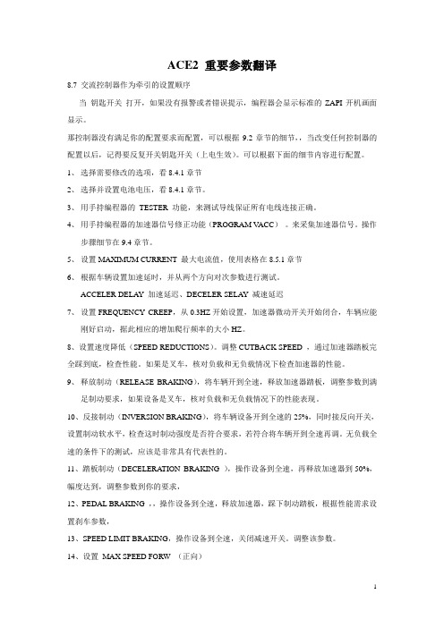
ACE2 重要参数翻译8.7 交流控制器作为牵引的设置顺序当钥匙开关打开,如果没有报警或者错误提示,编程器会显示标准的ZAPI开机画面显示。
那控制器没有满足你的配置要求而配置,可以根据9.2章节的细节,,当改变任何控制器的配置以后,记得要反复开关钥匙开关(上电生效)。
可以根据下面的细节内容进行配置。
1、选择需要修改的选项,看8.4.1章节2、选择并设置电池电压,看8.4.1章节。
3、用手持编程器的TESTER 功能,来测试导线保证所有电线连接正确。
4、用手持编程器的加速器信号修正功能(PROGRAM V ACC)。
来采集加速器信号。
操作步骤细节在9.4章节。
5、设置MAXIMUM CURRENT 最大电流值,使用表格在8.5.1章节6、根据车辆设置加速延时,并从两个方向对次参数进行测试。
ACCELER DELAY 加速延迟、DECELER SELAY 减速延迟7、设置FREQUENCY CREEP,从0.3HZ开始设置,加速器微动开关开始闭合,车辆应能刚好启动,据此相应的增加爬行频率的大小HZ。
8、设置速度降低(SPEED REDUCTIONS)。
调整CUTBACK SPEED ,通过加速器踏板完全踩到底,检查性能。
如果是叉车,核对负载和无负载情况下检查加速器的性能。
9、释放制动(RELEASE BRAKING),将车辆开到全速,释放加速器踏板,调整参数到满足制动要求,如果设备是叉车,核对负载和无负载情况下的性能表现。
10、反接制动(INVERSION BRAKING),将车辆设备开到全速的25%,同时接反向开关,设置制动软水平,检查这时制动强度是否符合要求,若符合将车辆开到全速再调。
无负载全速的条件下的测试,应该是非常具有代表性的。
11、踏板制动(DECELERATION BRAKING ),操作设备到全速,再释放加速器到50%,幅度达到,调整参数到你的要求,12、PEDAL BRAKING ,,操作设备到全速,释放加速器,踩下制动踏板,根据性能需求设置刹车参数,13、SPEED LIMIT BRAKING,操作设备到全速,关闭减速开关。
ZAPI表调整说明 叉车资料
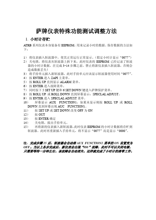
萨牌仪表特殊功能测试调整方法1. 小时计存贮ATRB系列仪表本身装备有EEPROM,用来记录小时的数据。
保存数据的方法如下:1)将仪表插入斩波器中,使其正常运行正常显示。
(假定小时计显示“0077”)2)关电锁,将仪表从斩波器上拆下来,此时仪表的EEPROM已经记录了斩波器的小时计数据,在完成3~14步骤之前,禁止将新仪表插入斩波器,否则会造成数据丢失!3)将手持单元插入新斩波器,此时手持单元应该显示斩波器使用时间“0077”。
4)按ENTER进入ZAPI主菜单。
5)按ROLL UP直到显示ALARM菜单。
6)按ENTER进入故障菜单。
7)同时按下5 SET UP键和6 SET DOWN键进入萨牌保护菜单。
8)按ROLL UP 或ROLL DOWN直到屏幕显示:SPECLAL ADJUST。
9)按ENTER进入SPECLAL ADJUST菜单。
10)屏幕显示AUX FUNCTION1,如果未显示则按ROLL UP或ROLL DOWN直到屏幕出现AUC FUNCTION1。
11)按SET UP或SET DOWN改变OFF为ON12)按OUT13)按ENTER确定14)关电锁,拔出手持单元。
15)再将新的仪表插入新斩波器,此时仪表EEPROM的小时计数据将存贮到斩波器。
此时再重新插入手持单元,将不显示“0077”而是显示“0000”。
注:完成步骤15后,斩波器会自动将AUX FUNCTION1菜单的ON设置变为OFF。
当以上各步完成后,新仪表会出现“098”故障,此时不可以关闭电锁,只需要等待一分钟左右。
该故障会自动消失。
这样就完成了小时计的清零工作。
2.电瓶电量放电曲线修正1)按ENTER进入ZAPI主菜单2)按ROLL UP直到显示ALARM菜单3)按ENTER进入故障菜单4)同时按下5键和6键进入萨牌保护菜单5)按ROLL UP或ROLL DOWN直到屏幕显示:SPECIAL ADJUST6)按ENRER进入SPECIAL ADJUST菜单7)屏幕显示AUX FUNCTION18)按ROLL UP或ROLL DOWN直到出现ADJUSTMENT#01和ADJUSRMENT#029)按SET UP或SET DOWN改变ADJUSTMENT#01和ADJUSTMENT#02的LEVEL值10)按OUT11)按ENTER确定ADJUSTMENT#01 修正电瓶电量100%~90%的上限值。
叉车使用说明书
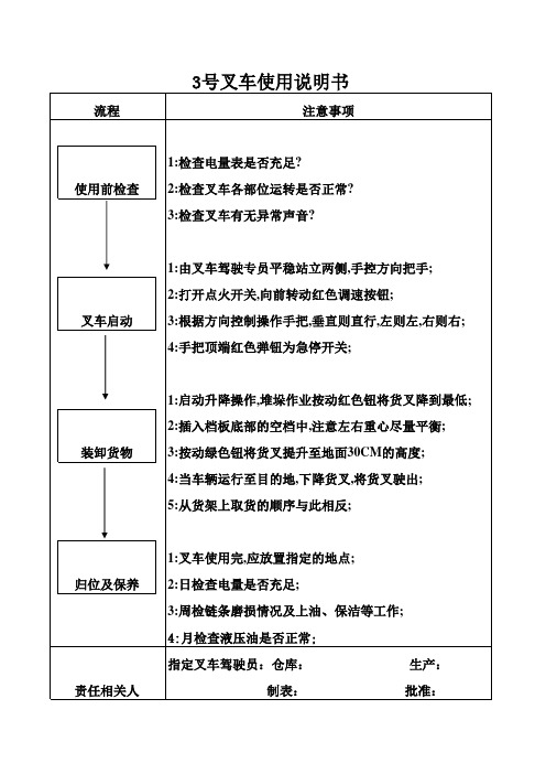
流程
注意事项
使用前检查
1:检查电量表是否充足? 2:检查叉车各部位运转是否正常? 3:检查叉车有无异常声音?
叉车启动
1:由叉车驾驶专员平稳站立两侧,手控方向把手; 2:打开点火开关,向前转动红色调速按钮; 3:根据方向控制操作手把,垂直则直行,左则左,右则右; 4:手把顶端红色弹钮为急停开关;
3:周检链条磨损情况及上油、保洁等工作;
4:月检查液压油是否正常;
指定叉车驾驶员:仓库:
生产:
制表:
批准:
装卸货物
1:启动升降操作,堆垛作业按动红色钮将货叉降到最低; 2:插入档板底部的空档中,注意左右重心尽量平衡; 3:按动绿色钮将货叉提升至地面30CM的高度; 4:当车辆运行至目的地,下降货叉,将货叉驶出; 5:从货架上取货的顺序与此相反;
归位及保养 责任相关人
1:叉车使用完,应放置指定的地点;
Байду номын сангаас
2:日检查电量是否充足;
叉车使用说明书

叉车使用说明书作业名称使用设备使用步骤:一、机动叉车1)机动叉车驾驶人员必须经过安全技术培训,取得上岗证。
2)须遵守厂区道路交通有关规定。
3)对叉车进行列行保养检修及一般故障排除。
4)严禁被装御、起重的物体重量超过核定起重量。
5)叉车铲运货物的长度以车寛为准,货物的宽度应短于叉齿的长度,货物高度应低于司机视平角,货物离地高度保持在30CM左右。
6)叉车升降时,严禁叉车下方站人。
7)若叉运货物超高、宽而影响司机的视野时,要有专人指挥行驶。
8)行车时保持车辆稳定,车速低于5KM/H.9)叉车行驶时,不许随车搭乘任何人员。
10)不准用汽油清洗车辆的机器部位,必须使用时,应先切断电源,远离火源。
11)车辆下坡时,严禁脱档滑行和熄火滑行。
12)驾驶员驾驶前严禁饮酒,行驶中不准吸烟、饮食、闲谈。
在行驶中发现制动机、方向盘有问题、应立即停车进行修复,严禁以手制动代替脚制动继续行驶。
编制批准文件编号生效日期版本页次叉车使用说明书作业名称使用设备使用步骤:二、人力叉车13)严禁站在人力叉车上快速滑行。
14)各厂地物料应摆放整齐,保持通道通畅,15)人力叉车上堆放物料,不得超过1.8M。
16)人力叉车搬移物料时,拉料人员应保持正确姿势,面朝前方,严禁快速拉车。
编制文件编号生效日期版本页次批准叉车使用说明书作业名称使用设备使用步骤:二、人力叉车1)严禁站在人力叉车上快速滑行。
2)各厂地物料应摆放整齐,保持通道通畅,3)人力叉车上堆放物料,不得超过1.8M。
4)人力叉车搬移物料时,拉料人员应保持正确姿势,面朝前方,严禁快速拉车。
编制文件编号生效日期版本页次批准。
叉车秤 XK3190-A12+(E)仪表说明书

叉车秤XK3190—A12+(E)仪表说明书第一章主要参数1.型号:xk3190-12+(E)称重指示器2.准确度:3级,n=30003.采样速度:10次/秒4.传感器灵敏度范围: 1.5~3mV/V5.分度值: 1 /2/5/10/20/50可选6.显示:6位LCD/LED, 6个状态指示7.大屏幕显示接口(可选);采用串行输出方式,电流环信号,传输距离≤2000米8.通讯接口(可选);RS232C: 波特率1200/24004800/9600可选9.使用电源: 免维护铅酸蓄电池SD6V4AH10.使用温度: 0~40℃11.储运温度: -25~55℃12.湿度: ≤85%RH仪表特色:仪表特色:1.高精度A/D转换,可读性达1/300002.调用内码显示方便,替代感量砝码观察及分析允差;3.特殊的软件技术,增强系统的抗振动能力4.数字滤波的速度,幅度以及稳定的时间可设置;5.称重计数功能(单件重量有断电保护)6.多种背光模式可选7.选配RS232通讯口,波特率可选;通讯方式可选;8.选配20ma电流环大屏幕通讯口;9.可定制非标改制型品种(可根据客户需求定制)叉车秤特色:快:搬运和称重同时作业的叉车电子秤,轻松压手柄,就显示标准重量。
省:省去中间环节,移动式直接称重,是传统称重的速度2倍,节省人工。
惠:一机两用,是移动叉车,还是一台地磅。
便:免插电使用,充一次电连续用一个星期。
第二章键盘功能【#】:开机自检时长按此键进入标定模式。
【功能】:在称重状态时,按此键大于5秒,进入用户设置模式。
按此键小于5秒,进入计数状态,【*】:在计数状态时,按此键进入取样样本数输入状态【去皮】:在称重状态时,按此键重量显示为零【开/关】:在关机状态时,按此键开机,在开机状态,按此键关机。
(A12+E无此键)第三章操作说明1.开机及开机自动置零1.接通电源后,仪表进行“000000~999999”的笔划自检,初始化完成后进入称重状态2.开机时,如果秤台重量偏离零点,但仍在设置的置零范围内,仪表将自动置零;若在设置的置零范围以外,仪表将自动报警“Err3”,提示超出置零范围,此时须去除秤台上重物货调整秤体零位或重新标定、设置。
- 1、下载文档前请自行甄别文档内容的完整性,平台不提供额外的编辑、内容补充、找答案等附加服务。
- 2、"仅部分预览"的文档,不可在线预览部分如存在完整性等问题,可反馈申请退款(可完整预览的文档不适用该条件!)。
- 3、如文档侵犯您的权益,请联系客服反馈,我们会尽快为您处理(人工客服工作时间:9:00-18:30)。
1 特性
1.1 特点
1.萨牌MDI多功能数字仪表是一个显示器,它适用于所有装有ZAPI高频电控器的各种形式的电动车辆。
2.萨牌MDI多功能数字仪表的信号取自斩波器,而不是电瓶,这样不同电压等级的车辆也可用同一仪表。
3.电瓶的放电状态由微处理器进行一定的换算模拟获得。
该换算考虑了制动及起动等大电流工况对电瓶的影响。
4.用萨牌MDI数字式手持单元,可以选择100种不同放电曲线。
5.萨牌MDI多功能数字仪表是一个以微处理器为基础的系统。
对电瓶放电状态测量是高精度的,具有很高的可靠性和灵敏度。
同时萨牌MDI多功能数字仪表还可以显示工作小时。
6.萨牌MDI多功能数字仪表有三个内部功能。
●显示放电状态。
●工作小时。
●显示控制系统故障。
7.萨牌MDI多功能数字仪表不直接连到电瓶,她仅与斩波器相连。
与传统显示仪表相比,萨牌MDI多功能数字仪表无需复杂接线,也节省了安装时间。
1.2 显示功能说明
1.2.a 发光二极管显示功能
萨牌MDI多功能数字仪表用发光二极管显示电瓶放电状态。
萨牌MDI多功能数字仪表有五个发光二极管,一红四绿,表示电瓶的放电状态。
充足电时,四个绿色发光二极管全亮。
随着电瓶不断放电,四个绿灯随电瓶剩余电量的减少逐步并按一定顺序熄灭,直至电瓶放完电,红灯开始闪烁,表示电瓶已开始过放电,斩波器进入低电压保护状态。
1.2.b 液晶显示功能
小时计:
在萨牌MDI多功能数字仪表中部装有液晶显示器,它可以用来显示
1.工作小时
2.系统故障,萨牌MDI多功能数字仪表显示故障状态时是以相应的代码表示,故障发生时,红色发光二极管将开始闪烁,以引起注意。
3.软件版本:电锁刚闭合时,萨牌MDI多功能数字仪表显示EPROM中的软件版本,即EP××,同时出现扳手图案。
4.其它信息,萨牌MDI多功能数字仪表上有三种图案,分别告知司机下列信息:
乌龟图案:
表示车辆处在“软”方式工作状态,在这种状态下,最大速度和加速度都被减小了。
扳手图案:
表示车辆规定的维护时间已到或表示出现故障或误操作,在出现故障和误操
作时还会显示一个代码,根据这个代码可以在控制器说明书有关故障诊断的章节中找出可能的故障原因,从而很快找到解决办法。
砂漏图案:
这个图案闪烁表示小时计正在工作。
2 设置和调整
用ZAPI数字式手持单元能实现下述设置和调整:
1.电瓶电量模拟换算
2.设置维护提示时间
3.工作时间记录
2.1 电瓶电量模拟换算
任何电瓶都有一条固有的放电曲线,即在一定的电流下,电瓶的剩余电量与电瓶两端的电压呈一定的关系。
萨牌MDI多功能仪表就利用了这一原理,模拟出一条电流在15%到27%控制器最大电流时的电瓶放电曲线。
这条放电曲线的始端和末端均可用手持单元来调整。
即:
●ADJUSTMENT #1 (调节#1):进入这个菜单可调整电瓶电量从100%到90%
时的电压临界值。
参数设置为0时,表示在同样的剩余电量下,电压临界值降低3.21%,参数设置为9时:表示在同样的剩余电量下,电压临界值增加电压范围2.75%。
参数为5,视同缺损,不进行修正。
●ADJUSTMENT #2 (调节#2):进入这个菜单可调整电瓶电量从20%到10%
时的电压临界值。
参数设置为0时,表示在同样的剩余电量下,电压临界值降低3.21%,参数设置为9时:表示在同样的剩余电量下,电压临界值增加电压范围2.75%。
参数为5,视同缺损,不进行修正。
参数为0电瓶使用时间长。
●电瓶电量从80%到30%时电瓶剩余电量与电压临界值的关系按线性变化模
拟。
下表表示缺损状态或参数为5时电瓶剩余电量与电压的关系:
●—旦控制器接通,电瓶容量显示就开始下降。
刚充足电的电瓶,电锁接通时显示100%电瓶容量。
除非在这种情况下;电瓶容量超过70%停止工作。
这时显示百分值(例如80%)持续的时间要比一般情况要长,这是因为实际电瓶容量高于显示电压值(80%)。
要等实际电瓶容量降到显示的百分数,电瓶容量显示才开始下降。
建议电瓶电量降到比较低时,如10%,20%或30%时就去充电,这样将有助于延长电瓶的寿命。
2.2 用ZAPI手持单元可对电瓶放电模拟曲线进行调正。
1)打开电锁,ZAPI手持单元显示出现如图信息
2)按ENTER进入主菜单
3)显示参数调整菜单
4)按ROLL UP键直到显示了“故障”ALARM菜单
5)按“ENTER”出进入故障ALARM菜单
6)显示斩波器中存储曾经发生过的故障或误操作
7)同时按下ROLL UP和ROLLDOWN键找到ZAPI保护菜单ZAPI PROTECT MENU
8)手持单元显示菜单标题,同时显示第一个子菜单
9)按ROLL UP 或ROLL DOWN,找到硬件设置HARDWARE SETTING菜单10)硬件设置标题HARDWARE SETTING出现
11)按ENTER进入
12)这时按UP或DOWN,进行调整操作
13)出现ADJUSTNENT #1时,同时出现预先设置或缺损的水平值。
14)按ROLL UP或ROLL DOWN修正水平值
15)显示新值
16)按OUT按钮退出菜单
17)最后按ENTER确认修正。
再按5)到12)步进行ADJUSTMENT #2的调整。
重要提示:
在对电瓶调整之前,建议用一台核定好的数字万用表测量一下电瓶电压,检查手持“测试”菜单中显示的电瓶电压值和电瓶实际值是否相同,若两个电压值不同要用手持单元对斩波器的测量电压进行校准,即进入“电压调整”菜单ADJUST BATTERY 进行调整,详细资料参阅相应斩波器的使用手册。
2.3 维护服务
萨牌MDI多功能数字仪表显示AL99,对应手持显示“CHECK UP NEEDED”,表示车辆到了预设的维护时间了。
什么时候显示AL99,或是否需要维护提示,可以用手持单元进行设置,即用手持单元进入“CHECK UP TYPE”菜单,按下表的定义进行设定。
在“CHECK UP TYPE”菜单中还可以设定提示方式,即若车辆到了应该维护的时间没有维护,
●“CHECK UP DONE”的设定若缺损,结果与设置成NONE一样,因为在
这种设置中不显示AL99,车辆不会降低速度行驶丧失,也不会停止工作。
为了清除AL99,要把“CHECK UP DONE”设置或ON,即进入手持单
元的硬件菜单(HARDWARE SETTING)中设置。
设置结束后进入退出
所有菜单。
断开电锁,10秒后再接通,AL99就被清除掉了。
●机器工作一定小时以后,如需激活维护提示功能,要把“CHECK UP
DONE”设置成ON,让小时计复位。
设置结束后进入退出所有菜单。
断
开电锁,10秒后再接通,维护提示就被启动。
2.4. 小时计存贮
萨牌MDI多功能数字仪表有一个自己的存储器,用来保存小时计的数据,若斩波器更换了,小时计的数据将转到新的斩波器中,这样车辆的维护资料就不会因更换备件而丢失。
这要求更换斩波器时按下述步骤进行操作
1.断开电锁开关,将萨牌MDI多功能数字仪表插头从斩波器中拔掉,插入手持单元
2.闭合电锁,进入HARDWARE SETTING 菜单,将“LOAD HM FROM MDI”
功能设置为ON。
有些版本此功能从“AUX FUNCTION1”菜单中设定。
3.断开电锁,取下手持单元,接上多功能表,合上电锁,新的控制器将立刻接收和保存原控制器中的小时计值。
必须注意:
对于“LOAD HM FROM MDI”设置缺损将被默认为设置成OFF,这种情况下这个功能未被激活,存储的小时值将被丢失。
为避免司机忘记设置参数“LOAD HM FROM MDI”,MDI多功能数字表显示“AL98”一分钟,这期间车辆停止运行,提醒司机小时计数据将要丢失,一分钟后如司机还是不去设置“LOAD HM MDI”,MDI的小时计数据将改写成新控制器的小时计数据,若控制器是新的,小时值就为0。
3 故障显示
萨牌MDI多功能数字表用相应的代码显示控制器的故障。
故障发生时,红色发光二极管闪烁,提示司机注意,并出现提示扳手图案
在MDI上显示故障译码
用MDI给出的显示,再照下表,可从相应的斩波器使用手册中找到相应的故障原因分析,从而很快解决问题。
如果不能解决,则司机能可将故障代码告诉维修中心,维修中心可依据这个故障代码给司机提供适当的帮助,或带上适当的。