Watson-Marlow 323E, 323S蠕动泵的说明书
齐力恒流泵基本型蠕动泵使用说明书
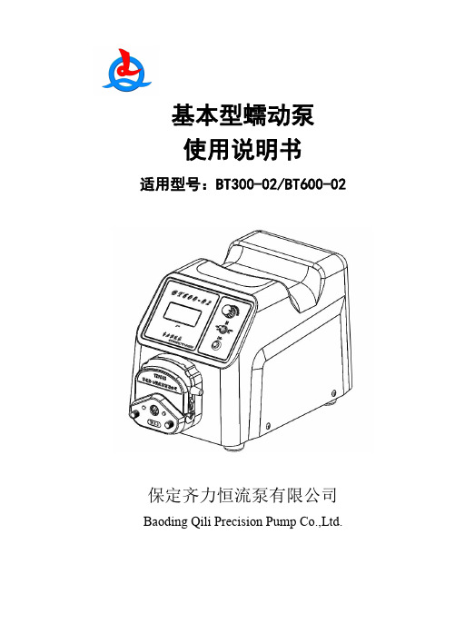
基本型蠕动泵使用说明书适用型号:BT300-02/BT600-02保定齐力恒流泵有限公司Baoding Qili Precision Pump Co.,Ltd.齐力恒流泵目录1.注意事项 (3)2.保修条款 (3)3.产品特点 (4)4.蠕动泵组成 (4)5.操作说明 (7)5.1名词解释.......................................错误!未定义书签。
5.2操作面板(前面板)介绍 (7)5.3基础操作说明...............................错误!未定义书签。
5.3.1切换光标...........................错误!未定义书签。
5.3.2调节参数...........................错误!未定义书签。
5.4界面介绍.......................................错误!未定义书签。
5.4.1工作界面...........................错误!未定义书签。
5.4.2编辑界面...........................错误!未定义书签。
1.泵头软管设置..................错误!未定义书签。
2.工作模式........................错误!未定义书签。
3.外控功能........................错误!未定义书签。
4.流量校准........................错误!未定义书签。
5.脚踏开关........................错误!未定义书签。
6.通讯功能........................错误!未定义书签。
6.后置接口介绍 (8)6.1散热风扇 (8)6.2反馈信号输出口 (8)6.3外控信号输入口 (8)6.4电源插座及开关(内置保险管) (10)齐力恒流泵1.注意事项●软管由于磨损可能产生裂痕,导致液体从软管中漏出,这时可能对人体和设备产生伤害,因此要经常检查并及时更换软管。
Pulsafeeder SOLIDMETER蠕动泵说明书

SOLENOID METERING PUMPS SI MPLE, RELIAB LE AND ROB UST.Pulsafeeder simplifies diaphragm metering pump technology.Technology is the key to delivering responsible products to the markets that we serve. Leading the way in the development of metering technologies, Pulsafeeder continues to set the standard for accuracy, reliability and safety.Helping customers find a new approach to an old problem is what we do best.For over 25 years, the PULSAtron product line has evolved into philosophy of design that continues to set the standards for the entire industry. Our engineers have developed a guided check valve system with a proven ‘seat and ball’ design that ensures reliable and accurate metering year after year.Our fin cooled Solenoid enclosure dissipates heat ensuring that the pressure handling capability of the pump can be maintained. The thermally protected Solenoid protects the pump from seizing up in extreme heat conditions with an automatic reset feature allowing the pump to resume operation upon cool-down. All PULSAtrons are tested and rated under hot conditions guaranteeing that the flow and pressure ratings meet the specifications.QUALITY PRODUCTS, TRUSTED SOLUTIONSPULSATRON2Pulsafeeder sets the standard for accuracy, reliability and safety.DIAPHRAGM METERING PUMP TECHNOLOGY.The key element which differentiates these pumps from other types is the TFElined elastomer diaphragm. This diaphragm is sealed against the reagent headforming a seal-less, leak free pumping chamber. The solenoid driver is connectedto the diaphragm to create the pumping motion. As the diaphragm moves awayfrom the face of the reagent head, it creates a vacuum which closes the dischargecheck valve and opens the suction check valve, drawing the pumped fluid into thepumping chamber. As the solenoid forces the diaphragm toward the face of thereagent head, the suction check valve closes and the discharge check valve opensallowing the liquid to flow out the discharge valve.Built to withstand harsh environments, PULSAtron metering pumps are reliable, dosing chemical accurately and safely. PULSAtron pumps offer versatile chemical control allowing them to be used in a large variety of applications. Precisely dose chemical, protecting costly equipment while optimizing chemical feed. This pump is ideal for all cooling tower applications including comfort cooling, industrial cooling, rinse, industrial process and wastewater.Fluid Handlers can select from multiple control configurations — with features and benefits that customers ask for.3PROPORTIONAL PROCESS CONTROLThe PULSAtron series metering pumps offer a wide variety of process control inputs.• 4-20mA inputs for metering control with Water meters and PLC’s.• Dry contact pulse inputs for use with PLC’s and dry contact water meters.• External remote stop input for use with a level wand for low chemical level control.AUTOMATIC DEGASSING TECHNOLOGYThe unique degas valve system is designed to allow air to be vented from the pumphead while minimizing the return fluid volume. This allows the pump to be totally self-priming which eliminates the need for a bleed valve. The degassing head also preventsthe pump from losing its prime due to gas build up, especially in applications wherethe pump is run intermittently with long off times between runs.Features and functions that create a simple to use, reliable, robust diaphragm metering pumps that matter to Fluid Handlers, assisting them in distributing chemical into their system effectively and safely.PREMIUM CONSTRUCTION.• Few moving parts• Optional wet-end materials• High viscosity handling• Long-life diaphragm• Leak-free designGUIDED BALL CHECK VALVE SYSTEM.• Dual ball check with TFE seats• Reduce back flow•Outstanding priming characteristicsBLEED VALVE ASSEMBLY STANDARD.• Safe and easy priming• Durable and leak-freeHIGHLY RELIABLE ELECTRONICS.• Advanced timing circuit• Rated hot for continuous duty• Thermal overloadAUTOMATIC CONTROL• External/remote pacing, with stop available on E Plus, HV, MP Series• External pace with auto/manual selection available on A Plus and C Series• Flow Verification available on MP pumps 100 psi or lessINTEGRATED TANK SYSTEM• 15 gallon tank• Bulk head assembly• Flow indicator• Float assembly• Pump mounting platePRE-ENGINEERED SYSTEM AND PANEL MOUNTED SYSTEMS • Pre-Configured system• Easy to install and operate• Mounting flexibility• Quick delivery• Designed for harsh environmentsFIVE FUNCTION AND FIVE FUNCTION DEGAS VALVE • Degas - Bypass gases and fluid with Five Function Degas Valve• Back pressure• Anti-Siphon• Air bleed• Discharge drain• Pressure Relief with Five Function Valve8• Automatic control, available with4-20mADC direct or external pacing, withstop function• Viscosities up to 20,000 CPS • Auto-Off-Manual switch • Manual control by on-line adjustable stroke length and stroke rate •Highly reliable timing circuit• 100:1 turn down ratio; 1000:1 on somemodels• Water resistant for outdoor installation• Manual control by on-line adjustable strokelength and stroke rate • Optional external pacing with Auto/Manual switch on A Plus • Internally dampened to reduce noise • Optional: External pace, external stopor both• 10:1 turn down ratio• Optional automatic control by externalpacing with prime switch• Manual control by on-line adjustablestroke length • Liquid low level option available to prevent loss of prime •Internally dampened to reduce noise•100:1 turn down ratio •Optional 4-20mA with stop function •Optional external pacing with stop function • Auto-Off-Manual selection switch withindicator lights • Built in circuit protection with easy access panel mount fuse • Clear hinged cover over controls for waterresistance• Automatic control, fully scalable4-20mADC, 20-4mADC or external pacing• Manual control allows for a combined1000:1 turn-down• Flow verification option is available onselect sizes• 144 x 32 pixel grapics/Backlit display • Relay and stop outputs • Simple prompts in plain language and programmable in four languages 6AN ISO 9001 CERTIFIED COMPANY 27101 AIRPORT ROAD • PUNTA GORDA, FL 33982PH: 941.575.3800 • FAX: 941.575.4085。
Watson-Marlow 520Di Pump 说明书

操作面板说明:Up :向上Start :启动:换档Stop :停止:确认Down :向下各键功能Start :启动。
泵开始运行。
Stop :停止。
泵运行停止。
Up :向上。
用于菜单选择—使光标上移一个选项。
在储存分装程序时,可通过它来依次显示“9-0”,空格和“Z-A”字符。
Down:向下。
用于菜单选择—使光标下移一个选项。
在储存分装程序时,可通过它来依次显示“A-Z”,空格和“0-9”字符。
Shift :换档。
按下Shift键后,在屏幕的坐下角会显示一个箭头符号,此时数字键盘的功能为对应键的黄色字符所表示的功能。
再按一次Shift键后,箭头符号消失,数字键盘恢复数字输入功能。
Enter :确认。
SHIFT, 0 ( . ):用于输入小数点。
SHIFT, 1 (DIRECTION):在设定分装参数时,设定泵的运行方向。
SHIFT, 4 (MAX):当泵处于手动控制模式或分装开始界面时,使泵以最高速度运行以实现快速预填充或快速排空。
SHIFT, 5 (CLEAR):在数字输入时,清除输入。
SHIFT, 6 (LOAD):用于调入储存在泵中的分装程序。
SHIFT, 7 (MENU):显示主菜单。
SHIFT, 8 (CAL):校准选项。
SHIFT, 9 (INFO):显示系统信息。
1. 开机注意:务必确认电压选择开关符合当前电压后才能开机!初次开机,系统会要求选择菜单语言,520Di目前提供有5种语言的操作界面,分别为英语、法语、德语、西班牙语和意大利语。
一般选择英语,后依次显示Watson-Marlow LOGO、泵基本信息,最后显示系统主菜单。
主菜单有5个选项,分别为:Dose:分装 - 设定、储存、调用分装参数,并执行分装操作。
Calibrate:校准 - 校准流量。
Manual:手动控制 – 手动操作520Di分装泵。
Network:网络控制 – 通过RS232通讯接口来控制520Di分装泵。
UN蠕动泵操作手册说明书
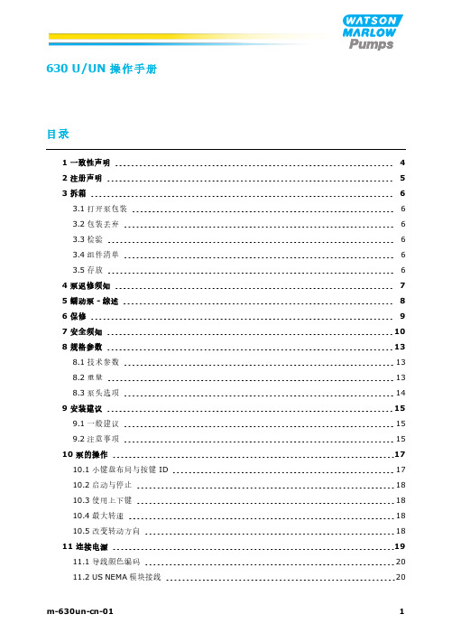
630U/UN操作手册目录1一致性声明4 2注册声明5 3拆箱63.1打开泵包装63.2包装丢弃63.3检验63.4组件清单63.5存放64泵返修须知7 5蠕动泵-综述8 6保修9 7安全须知10 8规格参数138.1技术参数138.2重量138.3泵头选项149安装建议159.1一般建议159.2注意事项1510泵的操作1710.1小键盘布局与按键ID1710.2启动与停止1810.3使用上下键1810.4最大转速1810.5改变转动方向1811连接电源1911.1导线颜色编码2011.2US NEMA模块接线2012启动检查表21 13控制线路2213.1上部D型接头2213.2下部D型接头2213.3标准25针D型接头:输入与输出2213.4标准-25针D型接头:供电限值3013.5N模块(标准型及SCADA型)3013.6标准型N模块3113.7SCADA型N模块35 14首次开启泵3814.1选择显示语言3814.2首次启动默认设置38 15重复启动泵41 16模式菜单42 17手动4317.1启动4317.2停止4317.3增加和降低流量4417.4MAX(最大转速)功能(仅限于手动模式)44 18流量校准4518.1设置流量校准45 19模拟模式4819.1模拟信号校准4919.2校准输入15019.3设置高信号值5119.4设置高流量校准5219.5设置低信号值5219.6设置低流量校准53 20MemoDose模式5520.1配置MemoDose5520.2设置流量5520.3恢复中断加注5620.4主加注量5720.5手动定量分装6021主菜单6221.1安全设置6221.2常规设置7021.3控制设置7921.4配置输出8121.5配置输入8321.6帮助84 22故障排除8522.1检漏8622.2错误代码8622.3技术支持87 23驱动维护88 24驱动器备件89 25泵头更换9025.1泵头更换90 26软管更换9126.1连续软管9126.2软管单元92 27订购信息9427.1蠕动泵订货号9427.2软管及软管单元订货号9527.3CIP和SIP程序9927.4泵头配件100 28性能数据10428.1620RE、620RE4和620R性能数据104 29商标110 30免责声明111 31发布历史1121一致性声明2注册声明Watson-Marlow Ltd Falmouth Cornwall TR11 4RU EnglandIn accordance with the Machinery Directive 2006/42/EC that if this unit is to be installed into a machine or is to be assembled with other machines for installations, it shall not be put into service until the relevant machinery has been declared in conformity. We hereby declare that:Peristaltic PumpSeries: 530 and 630 cased pumpsthe following harmonised standards have been applied and fulfilled for health and safety requirements:Safety of Machinery – EN ISO 12100Safety of Machinery – Electrical Equipment of Machines BS EN 60204-1 Quality Management System – ISO 9001and the technical documentation is compiled in accordance with Annex VII(B) of the Directive. We undertake to transmit, in response to a reasoned request by the appropriate national authorities, relevant information on the partly completed machinery identified above. The method of transmission shall be by mail or email.The pump head is incomplete and must not be put into service until the machinery into which it is to be incorporated has been declared in conformity with the provisions of the Directive. Person authorised to compile the technical documents:Andrew Green, Design & Engineering Director, Watson-Marlow Ltd. Place and date of declaration: Watson-Marlow Ltd, 31.07.2015 Responsible person:Simon Nicholson, Managing Director, Watson-Marlow LtdDeclaration of Incorporation3拆箱3.1打开泵包装仔细打开所有零件包装,保留包装,直到您确认所有组件均存在且状态良好。
蠕动泵使用标准操作规程
1.目的:建立BT300-1F蠕动泵标准操作程序,保障操作标准化。
2.适用范围:生产车间BT300-1F蠕动泵的操作。
3.责任与要求:BT300-1F蠕动泵操作人员按本规程实施,质量控制部负责监督本规程的实施。
4.内容:4.1.安装软管4.1.1. 将扳杆逆时针扳动180,打开上压块。
4.1.2.分别将两侧管卡向上抬起,将软管自然放入滚轮与上压块之间。
4.1.3.顺时针扳动扳杆180,使上压块下压到位,管卡可靠地卡住软管,以防止软管工作时窜动。
4.1.4.软管必须采用从蠕动泵厂商供应的灌装专用硅胶软管。
4.1.5.将BT300-1F蠕动泵电源插头插入220v/50Hz交流电源,启动BT300-1F蠕动泵电源开关,可见POWER指示灯亮,表明仪器进入工作状态。
4.2.功能设置在“运行界面”下,按一下【旋钮】进入“灌装设置”界面,通过转动【旋钮】可选择4个功能设置界面。
4.2.1. 灌装设置I.进入灌装设置菜单:a.此处不能对其它参数进行设置(如对泵头、软管、回吸角度等参数),初次使用时必须完成其它参数后方进行灌装设置,设置方法见“参数设置”。
b.在“灌装设置”界面下,按动【旋钮】进入下一界面,转动【旋钮】选择参数,灌装设置有四个参数,分别是液量、间隔时间、分配次数、流量。
II.液量:单次分配的液量如下图所示进入“液量”界面,转动【旋钮】至所需灌装量,按【旋钮】保存或按【返回键】取消设置,返回至上级界面。
III.“灌装设置”界面,按动【旋钮】进入下一界面,转动【旋钮】使“间隔时间”反白,按动【旋钮】进入“间隔时间”界面,转动【旋钮】调整间隔时间,按动【旋钮】保存或按【返回键】取消设置,返回至上级界面。
IV.分配次数:整个灌装过程总的罐装次数,范围是(1-999次)。
如下图进入“灌装设置”界面,按动【旋钮】进入下一界面,转动【旋钮】使“分配次数”反白,按动【旋钮】进入“分配次数”界面,转动【旋钮】调整分配次数,按【旋钮】保存或按【返回键】取消设置,返回至上级界面。
哈姆尔曼高压注射泵商品介绍说明书

Injection pumpsMethanolLDHIGlycolwww.process-pumps.deHammelmann offer a wide rangeof high pressure pumps for thechemical, oil and gas industries.Visit our website.Asphaltene InhibitorParaffin InhibitorCorrosion InhibitorScale Inhibitor INNOVATION THROUGH EXPERIENCEHammelmann Injection PumpsCalder offer a wide range of highpressure pump packages incorporatingHammelmann pumps for the chemical,oil and gas industries.Visit our website.www.process-pumps.deLabyrinth sealThis seal design which is absolutely unique to Hammelmann enables safe, reliable, continuous duty operation at pressures up to 3800 bar.The high pressure seal is formed within the minute cylindrical gap between the plunger and the labyrinth insert. The medium pressure is continuously reduced along the sealing surface.A minimum amount of high pressure leakage serving as lubricant is returned to the pump suction chamber.Exclusive sealing systemThe plunger connection to thepower end is self centering thereby drastically reducing sideways forces. This design ensures that there is virtually no contact between the plunger and the labyrinth insert resulting in extremely low component wear.When the pump unit is shut down the medium remains in thecylindrical gap so that a re-start,even after an extended shut down period is assured.Wear at the high pressure seal components does not lead to an abrupt breakdown of the pump but rather a gradual decrease in the flow rate. If the pump is driven in a control loop the r.p.m. of the driver will increase in direct proportion to component wear.S p e e dThe running speed of the pump is a direct indicator of the extent of wear.This enables long term planning of maintenance intervals and targeting ofspecific servicing tasks.We manufacture extremely compact Triplex and Quintuplex pump units for injection of Methanol, LDHI,Glycol and a range of inhibitors.Hammelmann high pressure pump units in the pressure range up to 15,000 psi (1035 bar) havedeveloped into the standard choice for offshore methanol injection applications with a reputation for extreme reliability and minimal maintenance requirements.Compact constructionExtensiveperformancerangeWith both Triplex andQuintuplex pumpsavailable we cansupply a veryextensive range offlow rates andoperating pressures.Power ratingsup to 1000 HPup to 750 kWFlow ratesup to 530 gpmup to 2000 l/minOperating pressuresup to 55,000 psiup to 3800 barHammelmann pumps producemaximum performance from aminimal footprint which is the resultof combining a compact integralspeed reduction gear end with theconcept of a vertical configuration.The vertical configuration channelsoscillating forces directlydownwards into the base structure.Unwanted lateral oscillations asproduced by horizontal pumps donot occur.The integral speed reducer with twinhelical gears arranged in a herringbone configuration ensures smoothrunning and even powertransmission without axially loadingthe bearings.A selection of gear ratios isavailable to allow the optimal choiceof driver. The compact constructioneliminates the need for an externalgear box and prevents rotaryoscillation. Mechanical efficiency isin excess of 95%.Industrial pumps, series 2ValvesThe suction valve (below) is a discring design incorporating a onepiece suction and discharge valveseat.FeaturesSeries 2 pumps employ the sameprecision engineered, field provencomponents as Hammelmannstandard production pumps. Theyare extremely compact with lowmaintenance costs and highoperational efficiency.Plunger speedUnitsOur high pressure pump units canbe supplied with electric motor, achoice of controls, safety valves andsuction side/discharge sidepulsation dampers.HDP 752HDP 482HDP 362HDP 252HDP172HDP 122HDP 72HDP 42HDP 2200,20,40,60,81,01,21,4Plunger speed m/sec1,61,8Moderate plunger speeds result inlow plunger and sealing elementwear characteristics.OUTINSealmonitoringsystemSeal monitoringThe condition of the low pressureseals may be monitored by installingan optional sealmonitoring system.MaintenancePump maintenance is carried outfrom above. Once the pump head isremoved you have complete,uncomplicated access to all highpressure components.Pump headThe total pressurised fluid productof the individual cylinders collectswithin a single high pressuredischarge bore within the pumphead valve block. The coaxial valvearrangement eliminates alternatingstress within the valve block.Suction chamberThe process fluid enters the pumpvia the suction chamber. Thistotally encloses the high pressurecomponents in a protective barrierand prevents emission of mediumto atmosphere.5,000 psi345 bar 10,000 psi 690 bar 15,000 psi 1035 bar Crankspeed HDP 22 D 20 D 15 D 12750 rpm 5 gpm 19l/min 2.6 gpm 10 l/min 1.6 gpm 6 l/min HDP 42 D 35 D 26 D 20750 rpm 15 gpm 60 l/min 8 gpm 31 l/min 4.7 gpm18 l/min HDP 72D 35 D 26 D 22750 rpm 21 gpm 80 l/min 11 gpm 42 l/min 7.4 gpm 28 l/min HDP 122 D 55 D 35 D 30530 rpm 50 gpm 192 l/min 19 gpm 74 l/min 13 gpm 51 l/min HDP 172 D 50 D 35 D 30555 rpm 61 gpm 232 l/min 28 gpm 108 l/min 20 gpm 75 l/min HDP 252 D 50 D 35 D 30555 rpm 102 gpm 387 l/min 47 gpm 181 l/min 32 gpm 124 l/min HDP 362 D 80 D 60 D 45490 pm 138 gpm 525 l/min 74 gpm 282 l/min 38 gpm 146 l/min HDP 482 D 80D 60 D 45465 rpm 171 gpm650 l/min92 gpm 349 l/min 47 gpm 181 l/min HDP 752D 80D 60D 45465 rpm285 gpm 1080 l/min159 gpm603 l/min79 gpm302 l/minPerformance data, Industrial pumps, series 2(Selection)Pos.Part name Pos.Part name 1Discharge valve 8Low pressure seal pack 2Valve housing 9Bellow 3Suction valve 10Crosshead4Suction chamber 11Connection rod 5Sleeve 12GearHDP 22/42: belt drive 6Labyrinth insert 13Crank shaft7Plunger14Crank section housing1234567891011121314Recommendations and standardsEU Machine directive 98/37/ EU ATEX 94/9/EUAPI 674 (with exceptions)Technical data, Industrial pumps, series 2Standard Option PlungerLabyrinth insert Ceramic Bronze-Valve housing 17% Chromium steel22% Duplex steelSealsNBR / PolyamideFKM / PEEK Suction chamberBronze18 – 10Chromium Nickel steel* Right reserved to make technical modificationsWetted parts materials *Gas tight designThe intermediate chamber of the pump can be outfitted with gas tight covers which provide a seal to atmosphere. The chamber is then charged with inert gas.This design ensures that no fluids, vapours or gases can escape to atmosphere via a worn plunger seal.1 = Priming valve2 =Safety valve3=Pressure regulating valveBellows systemThe bellows are the hermetic seals for the power end to prevent the intrusion of fluid or gas. They are available in FKM, H-NBR and PTFE.Process pumps, series 5ValvesTo ensure that the pumpconstructíon is appropiate for the pumped medium we have a number of alternative valve designsavailable. In the example shown below the suction and discharge valves are conical. The suction and discharge valve seats are combined in one component.FeaturesSeries 5 pumps are built to the highest standards of safety and reliability. We can supplycomponents from a wide range of materials to suit the pumped medium.Our latest variation of this pump series is the Zero emission where the pumped fluid is hermetically sealed within the pump, preventing leakage to atmosphere during operation.Plunger speedUnitsYour complete pump unit can be outfitted with suction and/or discharge pulsation dampersdimensioned, manufactured, tested and certified to your specification.1,4HDP 755HDP 485HDP 365HDP 255HDP 175HDP 125HDP 75HDP 45HDP 2500,20,40,60,81,01,2Plunger speed m/secInert gasOUTINThe series 5 pumps areconservatively rated for power with low plunger speeds ensuring limited wear of plungers and sealing elements.32Seal monitoring 11Performance data, Process pumps, series 5 (Selection)5,000 psi345 bar 10,000 psi 690 bar 15,000 psi 1035 bar Crank speed HDP 25 D 20 D 15 D 12420 rpm 2.9 gpm 11 l/min 1.5 gpm 6 l/min 0.9 gpm 3,5 l/min HDP 45 D 35 D 26 D 20500 rpm 10 gpm 40 l/min 5 gpm 20 l/min 3 gpm 12 l/min HDP 75 D 35 D 26 D 22490 rpm 13 gpm 52 l/min 7 gpm 28 l/min 5 gpm 19 l/min HDP 125 D 55 D 35 D 30365 rpm 35 gpm 133 l/min 13 gpm 51 l/min 9 gpm 35 l/min HDP 175 D 50 D 35 D 30385 rpm 42 gpm 160 l/min 19 gpm 74 l/min 13 gpm 52 l/min HDP 255 D 50 D 35 D 30390 rpm 71 gpm 270 l/min 33 gpm 126 l/min 23 gpm 87 l/min HDP 365 D 80 D 60 D 45340 rpm 95 gpm 363 l/min 51 gpm 194 l/min 26 gpm 101 l/min HDP 485 D 80 D 60 D 45365 rpm 137 gpm 520 l/min 73 gpm 279 l/min 38 gpm 145 l/min HDP 755D 80D 60D 45365 pm229 gpm867 l/min127 gpm483 l/min63 gpm242 l/minD = Piston dia [mm]1234567891011121314Technical data, Process pumps, series 5Wetted parts materials *Recommendations and standardsEU Machine directive 98/37/ EUATEX 94/9/EUAPI 674 (with exceptions)Other customer specified standards, i.e.NORSK M501NORSOK M650NACE MR 0175Pos.Part name Pos.Part name 1Discharge valve 8Low pressure seal pack 2Valve housing 9Bellows 3Suction valve 10Crosshead4Suction chamber 11Connection rod 5Sleeve 12GearHDP 25/45: belt drive 6Labyrinth insert 13Crank shaft7Plunger14Crank section housingStandardOptionPlungerLabyrinth insert Ceramic BronzeTungsten carbide Tungsten carbide Valve housing 22% Duplex steel25% Super duplex steel SealsNBR / PolyamideFFKM / PEEKSuction chamber 18–10 Chromium Nickel steel 25% Superduplex steel * Right reserved to make technical modificationsRound the clock operationThe compact design ofHammelmann pumps is a space saving advantage for installation on offshore platforms and FPSO’s.They are increasingly specified as the pumps of choice for offshore installations.02/09© Copyright Hammelmann Maschinenfabrik GmbH, Oelde, Germany. Right reserved to make technical modificationsAgbami Aker 1-6Allegheny Anna Platform Atlantis Auger Auger Apit Baton Rouge Black Widow BrazilBrutus/Glider BS4Cabida Block Canyon Express Conger Salsa Demos ForvieGarden Banks Garnet Gjoa Semi Groupo R Hickory HolsteinHorn Mountain HoumaIndep. Hub 3IndpendenceK2 Green Canyon K-FelsKikeh-Gusto King Kong Kings PeekKristin Longhorn Mad Dog Magnolia Marco Polo Max-Stena-Drill Mobile Rig Morvin Asgard Neptune Nile NoonanNorse Marchand Panama City Pegasus Perdido Petrorig Producer Scarebo Schahin SevanS. Timbalier Statfjord B & C Tahiti Talisman Tanzanite Tarantula TMT 1TyphonUrsa-Princess Valifornia West EdrillHDP 72 unit for methanol duty Op. pressure 12,000 psi – 830 bar Flow rate 6 gpm – 24 l/minHDP 555 pump unit for glycol and methanol dutyOp.pressure 10,700 psi – 740 bar, Flow rate 87 gpm – 333 l/minHDP 115 units for methanol duty Op. pressure 15,000 psi – 1035 bar Flow rate 1.5 gpm – 6 l/minHDP 122 unit for LDHI dutyOp. pressure 15,000 psi – 1035 bar Flow rate 7 gpm – 28 l/minHDP 175 units for methanol duty Op. pressure 5,300 psi – 370 bar Flow rate 46 gpm – 176 l/minHammelmannMaschinenfabrik GmbH Zum Sundern 13-2159302 Oelde – Germany Tel. +45 2522 760Fax +49 2522 76444******************www.hammelmann.deCalder Ltd.Gregory's Bank Worcester WR3 8ABUnited Kingdom Phone: 0044 1905 723 255Fax: 0044 1905 723 904***************.uk Calder Ltd.Gregory’s Bank Worcester WR3 8AB United KingdomPhone: 0044 1905 723 255Fax: 0044 1905 723 904***************.uk The compact design of Calder pump packages incorporatingHammelmann pumps, offers a space saving advantage for installation on offshore platforms and FPSO’s. They are increasingly specified as the pumps of choice for offshore installations.。
ATP-3200系列蠕动泵产品说明书

ATP-3200系列蠕动泵产品说明书一、蠕动泵的工作原理蠕动泵的工作原理非常简单,它就如同您的手指夹挤一根充满流体的软管,随着手指向前滑动,管内的流体就向前移动。
在我们的泵中是使用“压头”来代替您的手指工作的。
蠕动泵与其它类型的输送方法比较,具有许多优势:1.计量精确:低脉冲泵头满足流体高精度计量的要求。
2.免除污染:流体完全在管内输送,泵和流体都不会受到污染。
因此它是输送生物化学和医药制品中的粘性、磨蚀性流体的理想设备。
3.易于维护:改变泵的输送液体只需更换软管即可,非常简单快捷。
没有阀门及密封元件,切实节省因阻塞、腐蚀、密封泄漏等引起的费用。
蠕动泵已广泛应用于食品(奶制品、肉制品、果冻、蛋黄、调味品、果汁、软糖、巧克力、糖浆、维生素液等)、化工(油漆、涂料、乳胶、油墨、树脂、盐酸、硫酸、铁悬浮液、胶电解液等高粘性、强腐蚀性、磨蚀性溶液)、啤酒、制药、生物医学(血液、蛋白、组织液、稀释剂、药液等)以及造纸、陶瓷、建筑、采矿、废水及废物处理等行业。
二、特点:l专门为每一种尺寸的输液管设计的卡头,可最大限度的延长管子的使用寿命。
l可以同时驱动2-4个泵头,连接非常方便。
l输液头的瞬间启动和瞬间停止性能,使得输液更加准确可控。
l使用两个泵头错位并联输液,除增加一倍流量外,还可最大限度的减小输液脉动。
l留有外部接口,可与计算机或外部编程分配器相连,进行可编程操控。
l除有转速指示外,还有3种口径软管的流量直接指示。
l特殊的电路设计使得调速的操作非常平滑和精确。
l四位大型LED数字指示使得转速分辨率达到0.1rpm。
三、使用方法:1.由机器后部接入220V交流电源,再打开电源开关,开关本身即有发光指示。
同时,机器前面板上也有工作方式、状态和转速-流量等显示。
2.根据实际需要选择内控或外控工作方式:当机器后部的9针接口接入外控指令信号时蠕动泵即处于外控工作方式,否则即为内控工作方式。
3.内控工作方式下的使用:(1)根据实际需要选择使用蠕动管的规格和转速/流量显示方式,按动相应的选择键。
323 Temperature Series 2600温度控制器说明说明书
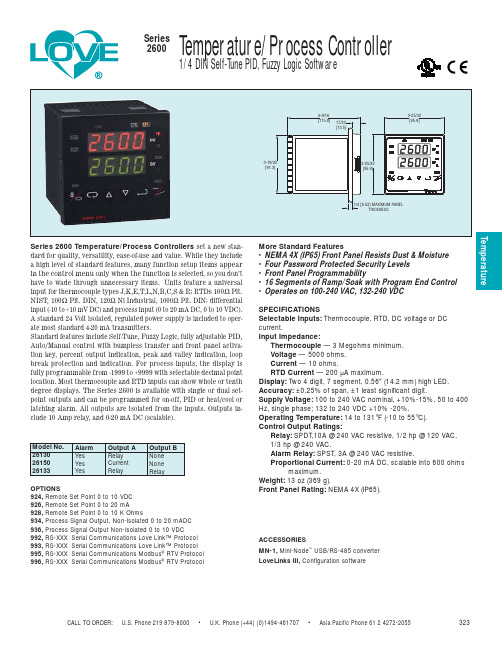
CALL TO ORDER: U.S. Phone 219 879-8000 • U.K. Phone (+44) (0)1494-461707 • Asia Pacific Phone 61 2 4272-2055323TemperatureSeries 2600 Temperature/Process Controllers set a new stan-dard for quality, versatility, ease-of-use and value. While they include a high level of standard features, many function setup items appear in the control menu only when the function is selected, so you don’t have to wade through unnecessary items. Units feature a universal input for thermocouple types J,K,E,T,L,N,B,C,S & R; RTDs 100Ω Plt.NIST, 100Ω Plt. DIN, 120Ω Ni Industrial, 1000Ω Plt. DIN; differential input (-10 to +10 mV DC) and process input (0 to 20 mA DC, 0 to 10 VDC).A standard 24 Volt isolated, regulated power supply is included to oper-ate most standard 4-20 mA transmitters.Standard features include Self-Tune, Fuzzy Logic, fully adjustable PID,Auto/Manual control with bumpless transfer and front panel activa-tion key, percent output indication, peak and valley indication, loop break protection and indication. For process inputs, the display is fully programmable from -1999 to +9999 with selectable decimal point location. Most thermocouple and RTD inputs can show whole or tenth degree displays. The Series 2600 is available with single or dual set-point outputs and can be programmed for on-off, PID or heat/cool or latching alarm. All outputs are isolated from the inputs. Outputs in-clude 10 Amp relay, and 0-20 mA DC (scalable).More Standard Features• NEMA 4X (IP65) Front Panel Resists Dust & Moisture • Four Password Protected Security Levels • Front Panel Programmability• 16 Segments of Ramp/Soak with Program End Control • Operates on 100-240 VAC, 132-240 VDCSPECIFICATIONSSelectable Inputs:Thermocouple, RTD, DC voltage or DC current.Input Impedance:Thermocouple — 3 Megohms minimum.Voltage — 5000 ohms. Current — 10 ohms.RTD Current — 200 µA maximum.Display:Two 4 digit, 7 segment, 0.56" (14.2 mm) high LED. Accuracy: ±0.25% of span, ±1 least significant digit.Supply Voltage: 100 to 240 VAC nominal, +10%-15%, 50 to 400Hz, single phase; 132 to 240 VDC +10% -20%.Operating Temperature:14 to 131°F (-10 to 55°C).Control Output Ratings:Relay:SPDT,10A @ 240 VAC resistive, 1/2 hp @ 120 VAC, 1/3 hp @ 240 VAC.Alarm Relay: SPST, 3A @ 240 VAC resistive.Proportional Current: 0-20 mA DC, scalable into 600 ohmsmaximum.Weight: 13 oz (369 g).Front Panel Rating:NEMA 4X (IP65).OPTIONS924, Remote Set Point 0 to 10 VDC 926, Remote Set Point 0 to 20 mA928, Remote Set Point 0 to 10 K Ohms934, Process Signal Output, Non-Isolated 0 to 20 mADC 936, Process Signal Output Non-Isolated 0 to 10 VDC992, RS-XXX Serial Communications Love Link™ Protocol 993, RS-XXX Serial Communications Love Link™ Protocol 995, RS-XXX Serial Communications Modbus ®RTV Protocol 996, RS-XXX Serial Communications Modbus ®RTV ProtocolACCESSORIESMN-1,Mini-Node ™USB/RS-485 converter LoveLinks III,Configuration software。
- 1、下载文档前请自行甄别文档内容的完整性,平台不提供额外的编辑、内容补充、找答案等附加服务。
- 2、"仅部分预览"的文档,不可在线预览部分如存在完整性等问题,可反馈申请退款(可完整预览的文档不适用该条件!)。
- 3、如文档侵犯您的权益,请联系客服反馈,我们会尽快为您处理(人工客服工作时间:9:00-18:30)。
WATSON-MARLOW BREDEL MANUALSm-323e-s-u-du-gb-06Contents1Declaration of conformity 22Declaration of incorporation 23Two-year warranty34When you unpack your pump 45Information for returning pumps 56Peristaltic pumps: an overview 67Safety notes78Pump specifications 98.1Pump features 98.2Dimensions149Good pump installation practice 159.1General recommendations 159.2Do’s and do not’s1610Connecting this product to a power supply1711Start-up check list1812Switching the pump on 1813Auto-restart facility 1914Manual operation 2015Keypad lock 2116MemoDose2217Automatic operation with analogue signals, remote control or RS232 link2317.1Analogue signals andremote control2417.2Automatic control wiringusing the 720N module2618Care and maintenance 2819Troubleshooting2819.1Error messages 2920Drive maintenance 3021Drive part numbers 3022Drive spares 3123Pumpheads3223.1Pumpheads: key safetyinformation3223.2313D and 314Dpumpheads3223.3313D and 314Dpumphead order codes3423.4313D and 314D flow rates 3523.5313D and 314D:maximum number of pumpheads3623.6313D and 314D:tubing part numbers3723.7314MC and 318MCmicrocassette pumpheads3823.8314MC and 318MCmicrocassette pumphead spares4023.9314MC and 318MCflow rates4123.10314MC and 318MCtubing part numbers4223.11501RL pumphead 4323.12501RL and 501RL2installation4323.13501RL and 501RL2tube loading4323.14501RL and 501RL2rotor settings4423.15501RL and 501RL2pumphead spares4523.16501RL and 501RL2flow rates4623.17501RL and 501RL2tubing part numbers4624Trademarks4725Warning not to use pumps in patient-connected applications 4726Publication history4727Decontamination certificate481 Declaration of conformityThis declaration was issued for Watson-Marlow 323E , 323S, 323U and 323Du pumps on November 1, 2007. When this pump unit is used as a stand-alone pump it complies with: Machinery Directive 98/37/EC, Low Voltage Directive 73/23/EC, EMC Directive 89/336/EC.This pump is ETL listed: ETL control number 3050250. Cert to CAN/CSAstd C22.2 No 61010-1. Conforms to UL std 61010A-1.See 8 Pump specifications.2 Declaration of incorporationWhen this pump unit is to be installed into a machine or is to be assembled with other machines for installations, it must not be put into service until the relevant machin-ery has been declared in conformity with the Machinery Directive 98/37/EC.Responsible person: Christopher Gadsden, Managing Director , Watson-Marlow Lim-ited, Falmouth, Cornwall TR11 4RU, England. Telephone +44 (0) 1326 370370 Fax +44 (0) 1326 376009.The information in this user guide is believed to be correct at the time of publication.However , Watson-Marlow Limited accepts no liability for errors or omissions. Watson-Marlow Bredel has a policy of continuous product improvement, and reserves the right to alter specifications without notice. This manual is intended for use only with the pump it was issued with. Earlier or later models may differ . The most up-to-datemanuals appear on the Watson-Marlow website: E, S, U, DuE, S, U, DuE, S, U, Du 3 Two-year warrantyWatson-Marlow Limited ("Watson-Marlow") warrants, subject to the conditions andexceptions below, through either Watson-Marlow, its subsidiaries, or its authoriseddistributors, to repair or replace free of charge, any part of the product which failswithin two years of the day of manufacture of the product. Such failure must have oc-curred because of defect in material or workmanship and not as a result of operationof the product other than in normal operation as defined in this pump manual.Watson-Marlow shall not be liable for any loss, damage, or expense directly or indi-rectly related to or arising out of the use of its products, including damage or injurycaused to other products, machinery, buildings, or property, and Watson-Marlow shallnot be liable for consequential damages, including, without limitation, lost profits,loss of time, inconvenience, loss of product being pumped, and loss of production.This warranty does not obligate Watson-Marlow to bear any costs of removal, instal-lation, transportation, or other charges which may arise in connection with a war-ranty claim.Conditions of and specific exceptions to the above warranty are:ConditionsProducts must be returned by pre-arrangement, carriage-paid, to Watson-Mar-low, or a Watson-Marlow approved service centre.All repairs or modifications must have been made by Watson-Marlow Limited, ora Watson-Marlow approved service centre or with the express permission ofWatson-Marlow.Warranties purporting to be on behalf of Watson-Marlow made by any person, including representatives of Watson-Marlow, its subsidiaries, or its distributors,which do not accord with the terms of this warranty shall not be binding uponWatson-Marlow unless expressly approved in writing by a Director or Manager ofWatson-Marlow.ExceptionsThe warranty shall not apply to repairs or service necessitated by normal wear and tear or for lack of reasonable and proper maintenance.All tubing and pumping elements as consumable items are excluded.Products which, in the judgment of Watson-Marlow, have been abused, misused, or subjected to malicious or accidental damage or neglect are excluded.Electrical surge as a cause of failure is excluded.Chemical attack is excludedAll pumphead rollers are excluded.Pumpheads from the 313/314 retain their one-year standard pumphead war-ranty. The drive they are attached to is subject to the two-year warranty as setout here.Ancillaries such as leak detectors are excluded.E, S, U, Du 4 When you unpack your pumpUnpack all parts carefully, retaining the packaging until you are sure all componentsare present and in good order. Check against the components supplied list, below.Packaging disposalDispose of packaging materials safely, and in accordance with regulations in yourarea. The outer carton is made of corrugated cardboard and can be recycled.InspectionCheck that all components are present. Inspect components for damage in transit. Ifanything is missing or damaged, contact your distributor immediately.Components suppliedWatson-Marlow 323E, 323S, 323U and 323Du pumps are supplied as:Dedicated 323E, 323S, 323U or 323Du pump drive unit fitted with one or more 313 or 314 pumpheads (see 8 Pump specifications).The designated mains power lead for your pumpPC-readable CDROM containing these operating instructionsQuick Start manualNote: Some versions of this product will include components different from thoselisted above. Check against your purchase order.StorageThis product has an extended shelf life. However, care should be taken after storageto ensure that all parts function correctly. Users should be aware that the pump con-tains a battery with an unused life of seven years. Long-term storage is not recom-mended for peristaltic pump tubing. Please observe the storage recommendationsand use-by dates which apply to tubing you may wish to bring into service after stor-age.E, S, U, Du 5 Information for returning pumpsEquipment which has been contaminated with, or exposed to, body fluids, toxic chem-icals or any other substance hazardous to health must be decontaminated before itis returned to Watson-Marlow or its distributor.A certificate included at the rear of these operating instructions, or signed statement,must be attached to the outside of the shipping carton. This certificate is requiredeven if the pump is unused. See 27 Decontamination certificate.If the pump has been used, the fluids that have been in contact with the pump andthe cleaning procedure must be specified along with a statement that the equipmenthas been decontaminated.E, S, U, Du 6 Peristaltic pumps - an overviewPeristaltic pumps are the simplest pump, with no valves, seals or glands to clog orcorrode. The fluid contacts only the bore of a tube, eliminating the risk of the pumpcontaminating the fluid, or the fluid contaminating the pump. Peristaltic pumps canrun dry.How they workA compressible tube is squeezed between a roller and a track on an arc of a circle,creating a seal at the point of contact. As the roller advances along the tube, the sealalso advances. After the roller has passed, the tube returns to its original shape, cre-ating a partial vacuum which is filled by fluid drawn from the inlet port.Before the roller reaches the end of the track, a second roller compresses the tubeat the start of the track, isolating a packet of fluid between the compression points.As the first roller leaves the track, the second continues to advance, expelling thepacket of fluid through the pump’s discharge port. At the same time, a new partialvacuum is created behind the second roller into which more fluid is drawn from theinlet port.Backflow and siphoning do not occur, and the pump effectively seals the tube whenit is inactive. No valves are needed.The principle may be demonstrated by squeezing a soft tube between thumb and fin-ger and sliding it along: fluid is expelled from one end of the tube while more is drawnin at the other.Animal digestive tracts function in a similar way.Suitable applicationsPeristaltic pumping is ideal for most fluids, including viscous, shear-sensitive, corro-sive and abrasive fluids, and those containing suspended solids. They are especiallyuseful for pumping operations where hygiene is important.Peristaltic pumps operate on the positive displacement principle. They are particularlysuitable for metering, dosing and dispensing applications. Pumps are easy to install,simple to operate and inexpensive to maintain.E, S, U, Du7 Safety notesIn the interests of safety, this pump and the tubing selected should only be used by competent, suitably trained personnel after they have read and understood this man-ual, and considered any hazard involved. If the pump is used in a manner not spec-ified by Watson-Marlow Limited, the protection provided by the pump may be impaired.This symbol, used on the pump and in this manual,means: Caution, refer to accompanying documents.This symbol, used on the pump and in this manual,means: Do not allow fingers to contact moving parts.This symbol, used on the pump and in this manual,means: Recycle this product under the terms of the EUWaste Electrical and Electronic Equipment (WEEE) Di-rective.Fundamental work with regard to lifting, trans-portation, installation, starting-up, maintenance and repair should be performed by qualified per-sonnel only. The unit must be isolated from mains power whilework is being carried out.Any person who is involved in the installation or periodic maintenance of this equip-ment should be suitably skilled or instructed and supervised using a safe system of work. In the UK this person should also be familiar with the Health and Safety at Work Act 1974.There is a user-replaceable type T1.0AH 250V fuse in the fuse drawer of the IEC mains connector atthe back of the pump, which also contains a spare fuse. In some countries, the mains power plugcontains an additional replaceable fuse. There are no user-ser-viceable fuses or parts inside this pump.There are moving parts inside the pumphead. Before opening the track, en-sure that the following safety directions are followed.Ensure that the pump is isolated from the mains power.Ensure that there is no pressure in the pipeline.If a tube failure has occurred, ensure that any fluid in the pumphead has been allowed to drain to a suitable vessel, container or drain.Ensure that protective clothing and eye protection are worn if hazardous fluids are pumped.Primary operator protection from rotating parts of the pump is provided by the pumphead track. See 23 Pumpheads.This product does not comply with the ATEX directiveand must not be used in explosive atmospheres.This pump must be used only for its intended purpose. The pump must be accessible at all times to facilitate operation and maintenance. Access points must not be ob-structed or blocked. The pump’s mains plug is the disconnecting device (for isolating the motor drive from the mains supply in an emergency). Do not position the pump so that it is difficult to disconnect the mains plug. Do not fit any devices to the drive unit other than those tested and approved by Watson-Marlow. Doing so could lead to injury to persons or damage to property for which no liability can be accepted.If hazardous fluids are to be pumped, safety procedures specific to the particular fluid and application must be put in place to protect against injury to persons.The exterior surfaces of the pump may get hot during operation. Do not take hold of the pump while it is running. Let it cool after use before handling it.No attempt should be made to run the drive without a pumphead fitted.E, S, U, Du8 Pump specificationsLabels fixed to the rear of the pump contain manufacturer and contact details,product reference number, serial number and model details.8.1 Pump features15-400 rpm3-400 rpmFour models of 323 drives are documented in this manual: 323E, 323S, 323U and 323Du, with varying functionality, as described earlier in this section. The 323E is fit-ted with a short-nosed gearbox, offers 15-400 rpm, and can be fitted with a 313 or 314 pumphead. The 323S, 323U and 323Du are available with a choice of gearboxes:a short-nosed gearbox, which offers 3-400 rpm and can be fitted with a 313 or 314pumphead, or a 314MC or a 318MC pumphead; and a long-nosed gearbox, which of-fers 1.5-220 rpm and can be fitted with a 501RL or a 501RL2 pumphead. See 23Pumpheads .323S, 323U, 323Du1.5-220 rpm323EIP (Ingress Protection) and NEMA definitions* Protect from prolonged UV exposure.Pump specificationsStandards8.2 Dimensions in millimetres 323E/D, 323S/D, 323U/D, 323Du/D323S/MC, 323U/MC, 323Du/MC323S/RL, 323U/RL, 323Du/RLUnit weightsE, S, U, Du9 Good pump installation practice9.1 General recommendationsPositionA correctly engineered installation will promote long tube life. Site the pump on aflat, horizontal, rigid surface, free from excessive vibration. Allow a flow of air aroundthe pump to ensure that heat can be dissipated. Ensure that the temperature aroundthe pump does not exceed 40C.Emergency disconnectionThe pump’s mains plug is the disconnecting device (for isolating the motor drive fromthe mains supply in an emergency). Do not position the pump so that it isdifficult to disconnect the mains plug. The STOP key on the keypad will always stopthe pump. However, it is recommended that a suitable local emergency stop deviceis fitted into the mains supply to the pump.ValvesPeristaltic pumps are self-priming and self-sealing against backflow. No valves arerequired in inlet or discharge lines. Valves in the process flow must be opened beforethe pump operates. Users are advised to fit a pressure relief device between the pumpand any valve on the discharge side of the pump to protect against damage causedby accidental operation with the discharge valve closed.The pump may be set up so that the direction of rotor rotation is clockwise orcounter-clockwise, whichever is convenient.Tubing materials: run-in adviceSta-Pure and Marprene tubing are hard to compress when new. When usingtubing made of these materials, the first 30 seconds should be at a speed of 10 rpmor greater. If the pump is run slower, the safety system built into pump drive’s soft-ware may cause it to stop and display an over-current error message.9.2 Do’s and do not’sDo operate the pump on a flat horizontal surface. The pump requires a free flow of air for cooling. Do not block the air vents beneath the pump or at the rear.Do not stack pumps more than three high.Do use only single phase mains electricity supplies.Do keep delivery and suction tubes as short and direct as possible - though ideally not shorter than 1m - and follow the straightest route. Use bends of large radius: at least four times the tubing diameter. Ensure that connecting pipework and fittings are suitably rated to handle the predicted pipeline pressure. Avoid pipe reducers and lengths of smaller bore tubing than the pumphead section, particularly in pipelines on the suction side. When pumping viscous fluids use pipe runs with a bore several times larger than the pump tube. Any valves in the pipeline (not usually needed) must not restrict the flow. Any valves in the flow line must be open when the pump is running.Do ensure that on longer tube runs at least 1m of smooth bore flexible tubing is con-nected to the inlet and discharge port of the pumphead to help to minimize impulse losses and pulsation in the pipeline. This is especially important with viscous fluids and when connecting to rigid pipework.Do site the pump at or just below the level of the fluid to be pumped if possible. This will ensure flooded suction.Do keep the pumphead track and all moving parts clean and free from contamina-tion and debris.Do run at slow speed when pumping viscous fluids. Flooded suction will enhance pumping performance in all cases, particularly for materials of a viscous nature.Do recalibrate after changing pump tubes, fluid, or any connecting pipework. It is also recommended that the pump is recalibrated periodically to maintain accuracy. When using Marprene or Bioprene continuous tubing, do re-tension the tube after the first 30 minutes of running.Tube selection: The chemical compatibility lists published in Watson-Marlow publica-tions are guides. If in doubt about the compatibility of a tube material and the duty fluid, request a Watson-Marlow tube sample card for immersion trials.We recommend using commercially available supplyvoltage surge suppression where there is excessive elec-trical noise.E, S, U, Du10 Connecting this product to a power supplyA well regulated electrical mains supply is required along with cable connections con-forming to the best practice of noise immunity. It is not recommended to site these drives alongside “dirty” electrical mains supplies such as 3-phase contactors and in-ductive heaters without special attention being paid to unacceptable mains-borne noise.The voltage selector is mounted in the switchplate at the rear of the pump. Set the voltage selector to 115V for 100-120V 50/60Hz supplies or 230V for 200-240V 50/60Hz supplies. Al-ways check the voltage selector switch before connecting the mains supply. Make suitable connection to an earthed, single-phase mains electricity supply. To comply with Safety Standards,the mains plug must be a separable plug (not a locking type).Input line fusing : type T1.0AH 250V 20mm time-delayed cartridge fuse, located in the combined mains IEC inlet socket and fuse drawer at the rear of the pump. Note: A spare fuse is also provided in the drawer .Conductor codingE, S, U, DuE, S, U, Du12 Switching the pump onSwitch on the power supply at the rear of the pump. The pump runs a power-ontest to confirm proper functioning of the memory and hardware. If a fault is found, an error message is displayed. See 19 Error messages .If the pump starts running look for the !symbol on the display. This ! symbol in-dicates that the pump is set for auto-restart. Press the STOP key if you need to stop the pump 11 Start-up check listEnsure that proper connections are achieved between the pump tube and suction and discharge piping.Ensure proper connection has been made to a suitable power supply.Ensure that the recommendations in section 9 Good pump installation practice are followed.Check the position of the voltage selector switchCheck the mains power switch at the rear of the pumpCheck the fuse in the mains inlet socket at the rear of the pumpEnsure that the mains IEC plug is correctly fitted in the mains IEC inlet socketThe pump is now ready to operate according to the defaults listed above.All operating parameters may be changed by means of key-presses. See 14 Manual operation .Do not use auto-restart for more than 10 starts per hour.We recommend remote control where a high number ofstarts is required.S, U, Du13 Auto-restart facilityAuto-restart will restart the pump after mains power interruptions. The pump will re-turn to its previous operating state. To install auto-restart:Mains power must be available to the pump to engage auto-restart.Stop the pump. Turn off the mains power switch at the rear of the pump.Hold down the START key and turn the mains power switch on. The !symbolwill show on the display.Start the pump. If the mains supply is interrupted the pump will automaticallyrestart when the mains power returns.Auto-restart is retained while the pump is switched off.To remove auto-restart switch off the mains power at the rear of the pump. Holddown the STOP key and turn the mains power switch on. The !symbol will go out.14 Manual operationYou can adjust the speed on the display while the pump is stopped or running.Use the UP key to increase the set speed. Use the DOWN key to reduce the set speed. We recommend that the speed is reduced to a minimum before start-ing the pump.The 323E increments in steps of 5rpm. The 323S,323U and 323Du increment in steps of 1rpm.Press the DIRECTION key to reverse the direction of rotation.The direction is shown by the rotation symbol. The di-rection may be changed while the pump is stopped or running.Start the pump with the START key.The rotation symbol will move to confirm that the pump is operating. The sym-bol is static when the pump is stopped.Stop the pump with the STOP key. The pump will stop immediately.The display will continue to show the previous speed and direction. The pump will return to this speed when the START key is pressed again.You can reduce the pump speed to 0 rpm with the DOWN key. The pump is still in the running state and the rotation symbol will continue to move. Press the UP key to return the pump to the minimum speed.E, S, U, DuThe keypad can be locked to prevent changes to pump speed or other settings, and make it possible only to start or stop the pump. The padlock symbol will show on the display.Set the pump running. Hold down the START key for more than 2 seconds to lock the keypad. The padlock symbol will show and only the START and STOP key will function.The keypad may also be locked while the pump is stopped. Hold down the STOP key for more than 2 seconds. The padlock symbol will show. The pump will start and stop but the speed and direction will be locked.To unlock the keypad while the pump is running hold down the START key for a further 2 seconds. The padlock symbol is removed. If the pump is stopped hold down the STOP key until the padlock symbol is removed.The pump can dispense a set quantity or dose of fluid each time the key is pressed. This is the MemoDose facility.Set the pump speed and direc-tion. Place a suit-able measuring container at the outlet andSTART the pump.When the required vol-ume of fluid has been dispensed, press the STOP key twice within half a second. This starts the MemoDose feature.The pump has made a record of the fluid it has just dispensed.You may now repeat this dose or adjust the quantity as required.The display will show “dos“ for 3 seconds. Then the display willchange to show 100%.Measure the quantity of fluid which has been dispensed. If the quantity is correct press START to repeat the dose.If the initial dose is larger than required use the DOWN key to reduce the volume % showing on the display. This will reduce the next dose to be dispensed by the pump.If the initial dose was smaller than required use the UP key to increase the next dose to be dispensed by the pump.Press START. The pump will dispense the new doseand the display will count down as this dose proceeds.The pump will stop when the new dose is complete.Measure the new dose. If it is correct you may nowrepeat this dose as often as required. The keypadlock can be used to prevent further changes.Use the UP and DOWN keys to further adjust thedose until the correct quantity is obtained. You mayadjust the dose size down to 1% or up to 999%Press the STOP key twice within half a second to exit MemoDose and return to manual operation.NotesYou must exit MemoDose to change pump speed and direction. But you may return to MemoDose and keep the present dose size. To retain the MemoDose value through a power interruption the pump must be in auto-restart.Press STOP twice to exit MemoDose and return to manual operation.Do not start the pump. Adjust the speed and direction showing on the display. Press STOP twice within half a second to return to MemoDose. The display willshow the previous % dose size. The pump will dose at the new speed and direc-tion.MemoDose doses can be triggered remotely. See 17.1 Analogue signals and re-mote contro l. Always check the dose size when changing pump tubes, fluid, or any connecting pipework.17 Automatic operation withanalogue signals, remote control, or RS232 linkThe pump will normally revert to manual control when it is switched on and display the present pump speed.Check that the pump is ready to run before selecting automatic operation. Remote control signals may start the pump without warning.Press the MODE key to select automatic operation. The pump will respond to the analogue and (323Du only) RS232 signal as soon as analogue is selected. The UP and DOWN keys will be disabled. Re-press the MODE key to return to manual control.The pump will return to the last set manual state, speed and direction.In an emergency press the STOP key. The pump will return directly to manual con-trol and stop.Auto-restart will retain automatic operation while the pump is switched off.Mode keypressU, DuE, S, U, DuU, Du17.1 Analogue signals and remote controlPump starting and direction may be remotely controlled by switches, and speed by analogue signals, connected to the 25-way D connector at the rear of the pump. The analogue interface will accept either 0-10 VDC or 4-20 mA signals.To select analogue operation press the MODE key until “ana” is showing in the dis-play. The AUTO icon will show on the display.Pump speed will increase with an increasing analogue signal. The pump will be stopped at 0V or 4mA. This interface is pre-calibrated at the factory and may not be altered. If the analogue signal is too high the pump will display an error message “E21” (Over signal). See 19 Error messages .The remote stop/start input works with both manual and analogue controlmodes. The remote direction input works only with analogue control mode.Never apply mains voltage to the 25-way D socket.Apply the correct signals to the pins shown below. Limit signals to the maximum values shown. Do not apply voltage across other pins. Permanent damage, notcovered by warranty, may result.Analogue voltage signal pins 4 and 14Input impedance 200 kohms Maximum voltage signal 10VAnalogue current signal pins 4 and 14link 3 and 15Input impedance 250 ohms Maximum current signal 20mASpeed controlStop/StartA remote stop/start switch may be connected between pins 7 and 17 of the 25 pin socket. Or a TTL compatible logic signal may be applied to pin 7. (Low 0V High 5Vmaximum. Ground to pin 17). This is available in manual and analogue operation.。