53220快速使用指南
BG-AMP2X20 Mini数字放大器用户手册说明书

BG-AMP2X20Mini Digital AmplifierAll Rights ReservedUser ManualPrefaceRead this user manual carefully before using this product. Pictures shown in this manual is for reference only, different model and specifications are subject to real product.This manual is only for operation instruction only, not for any maintenance usage. The functions described in this version are updated till March 2015. Any changes of functions and parameters since then will be informed separately. Please refer to the dealers for the latest details.TrademarksProduct model and its logo are trademarks. Any other trademarks mentioned in this manual are acknowledged as the properties of the trademark owner. No part of this publication may be copied or reproduced without our prior written consent.FCC StatementThis equipment generates, uses and can radiate radio frequency energy and, if not installed and used in accordance with the instructions, may cause harmful interference to radio communications. It has been tested and found to comply with the limits for a Class B digital device, pursuant to part 15 of the FCC Rules. These limits are designed to provide reasonable protection against harmful interference in a commercial installation.Operation of this equipment in a residential area is likely to cause interference, in which case the user at their own expense will be required to take whatever measures may be necessary to correct the interferenceAny changes or modifications not expressly approved by the manufacture would void the user’s authority to operate the equipment.SAFETY PRECAUTIONSTo ensure the best from the product, please read all instructions carefully before using the device. Save this manual for further reference.Unpack the equipment carefully and save the original box and packing material for possible future shipmentFollow basic safety precautions to reduce the risk of fire, electrical shock and injury to persons.Do not dismantle the housing or modify the module. It may result in electrical shock or burn.Using supplies or parts not meeting the products’ specifications may cause dama ge, deterioration or malfunction.Refer all servicing to qualified service personnel.To prevent fire or shock hazard, do not expose the unit to rain, moisture or install this product near water.Do not put any heavy items on the extension cable in case of extrusion.Do not remove the housing of the device as opening or removing housing mayexpose you to dangerous voltage or other hazards.Install the device in a place with fine ventilation to avoid damage caused byoverheat.Keep the module away from liquids.Spillage into the housing may result in fire, electrical shock, or equipment damage. If an object or liquid falls or spills on to the housing, unplug the module immediately.Do not twist or pull by force ends of the optical cable. It can cause malfunction.Do not use liquid or aerosol cleaners to clean this unit. Always unplug the power to the device before cleaning.Unplug the power cord when left unused for a long period of time.Information on disposal for scrapped devices: do not burn or mix with generalhousehold waste, please treat them as normal electrical wastes.Table of Contents1.Introduction (1)1.1.Introduction to BG-AMP2X20 Mini Digital Amplifier (1)1.2.Features (1)1.3.Package List (1)2.System Connection Introduction (2)2.1.Audio Output (2)2.1.1.Default output: 2x20Watt@4Ohm (2)2.1.2.Bridge connection: 1x40Watt@8Ohm (2)2.1.3.Dual-mono Output (3)2.2.Microphone input (3)2.2.1.48V phantom power input (3)2.2.2.MIC input (3)2.2.3.LINE input (3)3.Operation of the Control Panel and the IR Remote (4)3.1.Operation of the Control Panel (4)3.1.1.Audio switching (4)3.1.2.Volume/EQ controlling (4)age of the IR Remote (5)4.System Diagram (6)munication Protocol and Command Codes (7)6.Specification (8)7.Panel Drawing (9)8.Troubleshooting & Maintenance (10)9.After-sales Service (11)10.Warranty Information (Second Year Assurance) (12)11.Mission Statement (13)Introduction1.1. Introduction to BG-AMP2X20 Mini Digital AmplifierThe BG-AMP2X20 Mini Digital Amplifier is a compact-size digital amplifier (Class-D) with 3 inputs (2 line in and 1 balanced MIC). It is integrated with powerful functions, including bridge connection, dual-mono, EQ control, microphone mixer etc.It has a good application in different places, including classroom, small meeting room, lecture hall, bar, pub etc.1.2. Features2x20Watt@4Ohm as the default amplifier output.Bridge connection function. User can switch the Mini Digital Amplifier to be1x40Watt@8Ohm by bridge connection.Two stereo audio inputs, switchable by button, IR remote & RS232.Volume/Bass/Treble controllable by buttons IR remote & RS232.MIC port can support balance/unbalance signal, suppress the external noiseeffectively.Line audio output at 3.5mm jack, with volume controllable.Dual-mono function. User can sum up the stereo audio to two times mono audio.MIC mixer function. The microphone will be mixed to the line audio output, and be controlled separately.MIC input supports 48V phantom power, dynamic MIC and wireless MIC.Auto noise gate. It keeps detecting the audio and MIC input, will mute the output when there is no input.Ultra low inrush current, no need for power sequencing. This allows multiple Mini Digital Amplifier to be powered on simultaneously without overloading powercircuits.Convection cooler, fan is not needed.Antistatic case design: providing good protection for long-term and stableperformance.1.3. Package List1 x BG-AMP2X20 Mini Digital Amplifier (The mounting ears and Mini Digital Amplifier are as a whole.)2 x Pluggable Terminal Blocks1 x RS232 Cable1 x Power Adapter1 x Power Cord4 x Plastic Cushions1 x User ManualNotes:The IR remote and its battery are offered for charge separately.The IR receiver is also offered for charge.Please confirm if the product and the accessories are all included, if not, please contact with the dealers.System Connection Introduction2.1. Audio Output2.1.1. Default output: 2x20Watt@4OhmThe default output of amplifier is 2x20Watt@4Ohm, so user can connect the amplifier output in the regular way. As the picture below:2.1.2. Bridge connection: 1x40Watt@8OhmThe Mini Digital Amplifier has the bridge connection, to double the output power at******************************************************************** mono output, and the power is up to 40Watt.The bridge connection is:Connecting the two pins, like thisConnecting the four pins, like this2.1.3. Dual-mono OutputThe Mini Digital Amplifier also has the function of double-mono output. It can sum up the left and right channel, to be the mono audio output. In this way, the both of the outputs are showing the same mono audio.The connection is:2.2. Microphone input The microphone input of Mini Digital Amplifier has three modes, and different modesuse different connections, as the picture below:2.2.1. 48V phantom power inputWhen the switch turns to “48V”, the MIC input will provide a 48V phantom power. This is usually used for power supply for condenser microphone, Connection is: “+” connects to positive, “-” connects to negative and “╧” to ground.Note : In this mode, only condenser microphone can be connected with.2.2.2. MIC inputWhen the switch turns to “MIC”, the microphone input is used for connecting with dynamic microphone. There are two different connections:1) Unbalanced connection:“╧” connects to ground, and “-” connects to signal.“╧” connects to ground, and “+” connects to signal.2) Balanced connection: “+” connects to positive, “-” connects to negative and “╧”connects to ground.2.2.3. LINE inputWhen the switch turns to “LINE”, the microphone input is used for connecting with normal audio or wireless microphone output. There are two different connections:Connecting the four pins, like this1) Unbalanced connection:“╧” connects to ground, and “-” connects to signal.“╧” connects to ground, and “+” connects to signal.2) Balanced connection: “+” connects to positive, “-” connects to negative and “╧”connects to ground.Operation of the Control Panel and the IR Remote3.1. Operation of the Control PanelThe buttons provide the control of volume/EQ control and switching. The following content introduces audio switching and EQ control in detail.3.1.1. Audio switchingThere are two switchable stereo audio inputs, one 2xRCA input, and one 3.5mm jackinput, switchable through the buttons as below:3.1.2. Volume/EQ controllingThe line volume and MIC volume can be controlled by the buttons.The MIC Volume/LINE volume/LINE bass/LINE treble will be selected by the buttons, and controlled up/down/mute by the function buttons. Please check the picture below: S ourceSelectionFor example, to turn up the line volume, you should select the “LINE” first, and thenpress the button “ ”.3.2. Usage of the IR RemoteMute Mode: MIC : Mute the microphone volume. LINE : Mute the line volume. SPEAKER : UnmuteUse to transmit the infrared signal send by the IR remote. Audio Controlling Modes MIC : turn up/down themicrophone volume.LINE : turn up/down the linevolume.BASS : bass tuningTREBLE : treble of line volume. Audio Inputs1: RCA dual-mono audio inputs 2: 3.5mm jack Firstly toselect thefunctionfrom thismenu. Then to turn down/up the level, or mute the output.Notice: The IR remote, the IR receiver, and the battery of the IR remote are all offered for charge. System DiagramIR receiver head, works inconjunction with the IRremote. Please point the IRremote at the IR receiverwhen use, to avoid getting outof control as there is no signaldetected.3.5mm jack, insert it into the specialized socket (3.5mm) to connect the IR receiver with the amplifierCommunication Protocol and Command CodesCommunication Protocol: RS232 Communication ProtocolBaud rate: 9600 Data bit: 8 Stop bit: 1 Parity bit: none Command Function Description Feedback Code 1A1. Switching the audio to input 1 A: 1 -> 12A1. Switching the audio to input 2 A: 2 -> 10A0. Mute Audio of MIC and Line out Mute1A0. Mute audio of MIC Mute MIC2A0. Mute audio of line out Mute LIN0A1. Unmute Audio Unmute3A0. Switch on Noise Gate Gate On4A0. Switch off Noise Gate Gate Off600% Checking the working status A: 1 -> 1 Volume: 30 Bass: 00 Treble: 00601% MIC volume up Volume of MIC: 51 602% MIC volume down Volume of MIC: 51 603% Line volume up Volume of LINE: 51 604% Line volume down Volume of LINE: 51 605% Bass level up Bass of LINE: 04 606% Bass level down Bass of LINE: 04 607% Treble level up Treble of LINE: 04 608% Treble level down Treble of LINE: 04609% Initialization, back to the defaultsettingInit OK5[x][x]% Preset MIC volume, [xx] arrangesfrom [00] to [60].61 degrees in total.Volume of MIC: 507[x][x]% Preset line volume, [xx] arrangesfrom [00] to [60].61 degrees in total.Volume of LINE: 508[x][x]% Preset the bass level, [xx] arrangesfrom [00] to [08].9 degrees in total.Bass of LINE: 049[x][x]% Preset the treble level, [xx] arrangesfrom [00] to [08].9 degrees in total.Treble of LINE: 04 Notice:1: The letter inside bracket [ ] is the variable code, which is changeable.2: The bracket [ ] is not included to the RS232 commands. 3: Any dot “.” after the letters is part of the commands . Example 1:Switching the input 2 to the line out, RS232 command is: [2A1.] Example 2:Turning up the volume of line audio, RS232 command is: [603%] Example 3:Preset the MIC volume to “21” degree , RS232 command is: [521%] Example 4:Checking the working status of Mini Digital Amplifier, RS232 command is: [600%]SpecificationAudio Input Audio Output Input 2 stereo audio, 1 MIC Output 1 amplifier, 1 stereo audio InputConnector2 RCA1 3.5mm jack1 pluggable terminal block (3P ,3.81mm),Output Connector 1 3.5mm jack1 pluggable terminal block (4P , 5.08mm) InputImpedance >10KΩOutput Impedance 50Ω/stereo, 4~8Ω/Amplifier Audio General FrequencyResponse20Hz ~ 20KHzCMRR >70dB@20Hz~20KH zSNR80dB at maximumoutputBandwidth 20Hz ~ 25KHz StereoChannelSeparation >75dB@20Hz to20KHzTHD + Noise 1%@1KHz, 0.3%@20KHz at nominal levelVoltage Gain 32dB Power Output 2x20 Watts (4 Ohms) Control FunctionRS232 Control3-hole phoenixconnectorPanel ControlOptional button controlIR Remote Optional IR remotePanel DrawingTroubleshooting & Maintenance1) When there is no output audio:Check if there is any signal at the input.Check if there is any signal at the output.We can check these by using an oscilloscope or a multimeter. If there is nosignal input/output, maybe the input/output cables broken or the connectorsloosen, please change for another cable.Check if the output port number is the same with the controlled one.If not the problem mentioned above, probably there is something broken inside the unit, please send it to the dealer for repairing.2) If the POWER indicator doesn’t work or no respond to any operation, please makesure the power cord connection is good.3) If the output sound is interfered, please make sure the system is grounded well.4) If the static becomes stronger when connecting the audio connectors, it probablydue to bad grounding, please check the grounding and make sure it connected well, otherwise it would damage the converter.5) If the Mini Digital Amplifier amplifier cannot be controlled by the keys on the frontpanel, RS232 port or IR remote, the unit may have already been broken. Please send it to the dealer for repairing.After-sales ServiceIf there appear some problems when running the device, please check and deal with the problems referring to this user manual.1) Product Limited Warranty: We warrant that our products will be free from defectsin materials and workmanship for one year, which starts from the first day you buy this product (The purchase invoice shall prevail).Proof of purchase in the form of a bill of sale or receipted invoice which is evidence that the unit is within the Warranty period must be presented to obtain warranty service.2) What the warranty does not cover (servicing available for a fee):Warranty expiration.Factory applied serial number has been altered or removed from the product.Damage, deterioration or malfunction caused by:Normal wear and tearUse of supplies or parts not meeting our specificationsNo certificate or invoice as the proof of warranty.The product model showed on the warranty card does not match with the model of the product for repairing or had been altered.Damage caused by force majeure.Servicing not authorizedAny other causes which does not relate to a product defectDelivery, installation or labor charges for installation or setup of the product3) Technical Support: Email to our after-sales department or make a call, pleaseinform us the following information about your cases.Product version and name.Detailed failure situations.The formation of the cases.Remarks: For any questions or problems, please try to get help from your local distributor.Warranty Information (Second Year Assurance)Second Year AssuranceBZBGEAR wants to assure you peace of mind. We're so confident in the quality of our products that along with the manufacturer's one-year limited warranty, we are offering free second-year warranty coverage upon registration*!Taking advantage of this program is simple, just follow the steps below:1. Register your product within 90 days of purchase by visiting/warranty.2. Complete the registration form. Provide all necessary proof of purchase details, including serial number and a copy of your sales receipt.Forquestions,**************************************************.For complete warranty information, please visit /warranty or scan the QR code below.*Terms and conditions apply. Registration is required.Mission StatementBZBGEAR manifests from the competitive nature of the audiovisual industry to innovate while keeping the customer in mind. AV solutions can cost a pretty penny, and new technology only adds to it. We believe everyone deserves to see, hear, and feel the advancements made in today’s AV world without having to break the bank. BZBGEAR is the solution for small to medium-sized applications requiring the latest professional products in AV.We live in a DIY era where resources are abundant on the internet. With that in mind, our team offers system design consultation and expert tech support seven days a week for the products in our BZBGEAR catalog. You’ll notice comparably lower prices with BZBGEAR solutions, but the quality of the products is on par with the top brands in the industry. The unparalleled support from our team is our way of showing we care for every one of our customers. Whether you’re an integrator, home theater enthusiast, or a do-it-yourselfer, BZBGEAR offers the solutions to allow you to focus on your project and not your budget.。
T20无线AP快速使用手册V1.0

______快速使用手册V1.0______本手册用于AP系列-室内型AP的快速安装,将会大致的指导您如何应用室内型AP,通过简洁准确的操作方式,为网络建设、维护人员以及每一个用户提供一个便利的图形界面,实现对AP的配置管理。
1快速配置指南第一步:设备连接与供电●设备接口说明:LAN Power Reset图1 AP设备接口●Reset:两种方法恢复设备至出厂设置状态:位于系统管理→配置管理页面的“恢复出厂”按钮;常按Reset按键5秒至10秒,然后释放,设备将会重启并恢复到出厂默认设置。
第 3 页 共 17 页设备供电:吸顶路由可支持以下三种供电方式(具体方式视不同机型略有差异,请参考对应产品规格说明书加以区别),连接方法如下图所示: 1) 电源适配器供电图 2 设备连接与电源适配器供电示意图2) Passive POE 和路器供电注意确保设备在重新启动过程中供电正常,否则有可能会造成设备损坏,不能正常开机LAN 口PC220V 交流电源适配器LAN 口POELANPOE 合路器PC220V 交流电源适配器图3 设备连接与Passive POE供电示意图3)POE Switch交换机供电(802.3af)POE以太网交换机PCLAN口图4 设备连接与POE以太网交换机供电示意图不正确的连接方式或使用非产品附带的电源适配器以及POE转接头,可能会损坏设备!注意第二步:启动与登陆1)按上图连接好AP设备与电脑2)配置PC本地连接IP地址为192.168.2.X (X为2-254),与AP同网段,子网掩码255.255.255.0 如图5、6:图5 设置电脑网卡IP图6 设置电脑网卡IP3)无线连接设备.完成基本配置后,若想通过无线方式上网,须按照本文开头的设置“本地连接”的方式设置电脑的“无线网络连接”。
然后右键单击“无线网络连接”选“查看可用的无线连接”;本产品默认SSID为:AP-XXXX无线密码:空第5 页共17 页图7无线连接设置图8无线连接设置图9无线加密连接设置第 7 页 共 17 页4)使用IE 浏览器访问 http://192.168.2.1 ,弹出登陆画面,默认登陆用户名:admin 密码:admin 如图10.图10 网页地址与登录第三步:设置向导配置①登陆web 管理页面后,点击“设置向导”→选择“扫描”→选择“接入的SSID ”→“输入相对应的密钥”→“选择对应的连接模式:PPPOE 、DHCP 、静态地址”→“下一步”。
VAPRO_5520组织渗透压计使用说明
VAPRO 5520组织渗透压计使用说明建议首次使用此仪器时遵照以下流程进行操作:1、检查各种配件和耗材是否齐全2、将仪器放置在合适的工作环境中,平坦桌面上避免震荡3、待仪器温度和环境温度适应达到平衡后,插上电源连接线,打开仪器开关(仪器工作环境温度范围:15-35o C)4、装样校准仪器,注:使用标准溶液的顺序为:290mmol/Kg,1000 mmol/Kg, 100 mmol/Kg,标准液为一次性消耗品,每次不管剩余多少都要扔掉5、进行热电耦清洁测试,如果达不到要求需要对热电耦进行清洗6、判断仪器是否校准合格,若不合格,需再次进行校准,必要时对热电耦进行清洗(清洗步骤详见说明书P46-P56)。
7、以上步骤完成后即可载入样品进行测试。
相关细节及注意事项总结如下:1、如何载样?具体参照仪器使用说明书P36-38。
注:每次只能放置1个载样纸片,放置多个会导致测试结果偏高。
移液枪量取液体体积:10ul,允许偏差范围:10%,多于11ul可能会污染测量室内的细微热电耦。
需要注意的地方:可以用移液枪枪头尖端轻轻压平载样纸片,载样过程操作动作最好迅速,及时把样品槽推进测量室内,防止水分的挥发而影响测量的准确度。
2、每次测完样品后如何清洗载样槽?清洁工具:棉布或丝绸,不能用面巾纸或者纱布擦拭。
擦拭之后若还有残余物,需要用专用清洗液进行清洗。
3、载样槽清洗过程中应该注意的地方?不可用手触摸载样槽,每次测定之后不能用镊子等金属工具取出载样纸片。
尽量缩短清除残余样品的时间,并尽快加样进行测试。
4、载样槽清洗的标准?擦拭明亮,完全干燥,然后才能加下一个样品。
5、如何进行校准?注:使用标准溶液的顺序为:290mmol/Kg→1000 mmol/Kg→100 mmol/Kg,标准液为一次性消耗品,打开安剖瓶盖之后的几个小时内标准液可以使用,之后每次不管剩余多少都要扔掉。
(安剖标准液瓶直接用手轻掰即可打开,打开过程要小心,注意别伤到手指)3种标准液校准时允许的偏移幅度分别为290mmol/Kg--+3 mmol/Kg,1000 mmol/Kg--+5 mmol/Kg, 100 mmol/Kg--+2 mmol/Kg。
FLUKE54200中文操作指南
FLUKE54200中文操作指南仪器的设定和检查 开机之后, 仪器自动地被设定为上一次关机之前的设置。
例如:图3-1. 主菜单按standard 软键(F1) 出现选定国家的省缺设置子菜单,例如,英国图3-2. 该国家的视频标准和伴音制式按edit 软键(F3) 弹出预先定义的国家目录列表菜单 按↑或者↓软键(F1或者F2)选择国家,例如,德国。
如果你需要的国家没有被列出, 就选择一个和你要使用的国家相同或相似的视频标准和伴音制式。
图3-3. 预先定义的国家目录列表菜单按enter 软键(F5)确认你的选择 屏幕显示出你所选择国家的视频标准和伴音制式图3-4. 所选国家的视频标准和伴音制式 如果你的电视机不支持该制式,可以通过按↑或者↓软键(F1或者F2)来选择你所需要的视频标准和伴音制式,例如,FM Germany按edit 软键(F3)按↑或者↓软键(F1或者F2)来选择你所需要的标准和伴音制式,例如,FM Mono按enter 软键(F5)确认你的选择再按enter 软键(F5)回到主菜单图3-5. 设定后的主菜单检查video(视频) 和 chroma(色度) 的幅度是否设置为 100%如果不是,按video 软键(F2),屏幕显示出video(视频)子菜单当前所有的设置。
图3-6. video(视频)子菜单当前的设置按edit 软键(F3)弹出一个可以输入数字的菜单图3-7. video(视频)幅度设置 使用数字按键输入100 按enter 软键(F5)确认你的输入 按↑软键(F2)来选择chroma(色度)使用数字按键输入100 按enter 软键(F5)确认你的输入 再按enter 软键(F5)回到主菜单图3-8. 改变设置后的主菜单按显示屏右边的FREQ 键,选择适当的射频载波频率,例如,203.25 MHz 弹出一个数字输入菜单图3-9. 载波频率设置使用数字按键输入203.25按enter 软键(F5)确认你的输入图3-10. 选定载波频率将你的电视机设置为相同的频率或相应的电视频道,在这个例子里,是9频道。
SPAD502叶绿素仪操作手册.doc
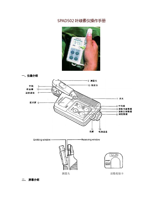
SPAD502叶绿素仪操作手册一、仪器介绍测量头读数校验卡二、屏幕介绍1、N表示存储在机器内的数据个数;No表示当前数据序号。
2、低电显示,出现这个图标表示电池电量已耗尽或者电池应该更换3、表示当前显示的值为平均值4、测定数值或操作信息举例:1、下面屏幕表示:第26个数据,其测量值为32.7。
2、若数值小于100,显示小数点后1位,当数值大于100或接近100时,无小数点显示。
当数值大于50后,小数点会闪烁,表示这个数值不能保证十分精确。
3、当按了“平均”以后,显示的为当前数值的平均值4、当按了“浏览数据”后,显示以前存储数据。
5、当校准时出现上面此图标表示探测头没有正确关闭;当环境温度变化10度以上,此图标出现,表示要重新校准,一旦重现校准,所存储的数据都将被删除。
出现(1)图示,说明透射光过量,需要重新校准。
出现(2)图示,说明透射光不足,需要清洁测量头的发射窗和接收窗,然后重新校准。
如果清洁后仍继续出现此图示,有可能是出现故障了。
6、出现此图示,说明测量头没有完全关闭,重新测量。
如果一直显示此图示,有可能出现故障了。
7、出现此图示,说明透射光不足,需要清洁测量头的发射窗和接收窗,如果仍出现此图示,有可能此样品不能测量。
8、出现此图示,说明电量不足,需更换电池。
9、出现此图示,说明仪器工作不正常,将开关打到关,然后再打开,如果仍出现此图示,说明仪器坏了,需要修理。
三、电池的安装:拧开SPAD502下部的电池盒盖,正极向里安装2节AA电池;再拧上盖。
可以使用碱性电池和碳锌电池,不能使有性质不同或电量不同的电池。
四、仪器的校准:每次开机都需校准,请遵照以下程序进行1)打开电源2)不放样品,按下探测头,直到听到“哔”一声,屏幕显示N=0 ―――表明校准完成。
3)如果持续蜂鸣,出现下面图示,表示校准未正确完成,按2)重复进行校准。
如果出现下面图示,则发射窗或接收窗需要清洁,清洁后按2)重新校准。
五、测量在野外,SPAD502使用非常便捷。
CTRL20调试手册1
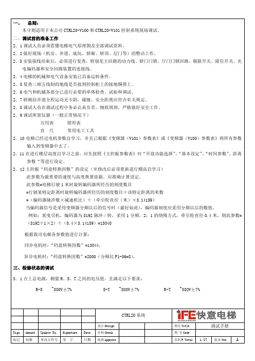
CTRL20 系统
设计 Design 图名 Title 图 号 Code 页码 P/Total
调试手册
3/27
版本 Ver.
Sign 标记
Amount
Update No. 更改文件号
Signature
Date 日期
审核 Check 批准 Approve
处数
签
字
A
五、电梯运行状态的调试。 5.1 将电梯运行到中间楼层,然后进入轿厢,使电梯工作在有司机状态下、直驶状态下,试试电梯的运行状态,检查 是否正常。 5.2 将“开放功能选择”中的“司机时不理外召”功能打开,再进入监控画面第三页,按“换行”按钮,直到旁边出 现“选层” 、 “内召”字样为止,然后通过按动按钮给予主控板内指令信号,使电梯关门、启动、运行、换速、 平层、再开门。 六、 在电梯运行正常情况下,首先调整电梯的舒适感。 6.1 觉得电梯运行的舒适感不够理想,首先应检查系统的机械情况,如导靴的间隙,导靴的润滑,钢丝绳的松紧度是 否均匀等,这些都会影响电梯运行的舒适感。机械部份经检查没有问题后,才可对控制部份进行调整。 6.2 由于变频器是按给定的起、制动曲线来控制电动机的运行,因此给定的起、制动曲线形状,变频器控制的电机反 馈速度对曲线的跟踪程度及控制单元发给变频器控制信号的时序都将影响电梯运行的舒适感, 此时可重点调整变 频器中的 C1-01,C1-02,C1-03,C1-04,C1-06,C5-01,C5-02, C5-03 等参数,主控板的参数:起动零速时间一、起动零速时间二、停止零速时间一、停止零速时间二等。 6.3 让电机在最高输出频率运转。 6.3.1 逐渐调整起动零速时间一、起动零速时间二、停止零速时间一、停止零速时间二的值,以达到最好的运行舒适 感. 七、平层精度的调整 7.1 平层精度的调整应在舒适感调整完毕后进行,准确平层首先要保证轿顶光电(永磁)感应器及隔磁板的安装位置 十分准确,即当轿厢处于平层位置时,隔磁板的中心点必须与中间一个光电(永磁)感应器的中心点重合,并 且隔磁板与光电(永磁)感应器的面要垂直。 7.2 首先调整楼层的平层精度,当电梯每次向上运行时,轿厢地坎高出厅门地坎而当电梯每次向下运行时轿厢地坎低 于厅门地坎,则可减小变频器 D1-03 的数值,反之即增加。直到 D1-03 的值调整至最合适的值为止。 7.3 楼层的平层精度调整,也可通过更改距离参数菜单中的: “上零速指令距离”和“下零速指令距离”的数值来达 到目的。 如果上行时轿厢高出地坎,则减小“上零速指令距离”的数值,否则加大“上零速指令距离”的数值; 如果下行时轿厢高出地坎,则加大“下零速指令距离”的数值,否则减小“下零速指令距离”的数值, 。 7.4 最后仔细核对各个功能(比如:司机、满载、超载、到站钟、到站灯、并联、群控等)是否正确,如果正确,则 整个调试工作结束。 八、安装调试注意事项 8.1 操作变频器时,切勿动梯,否则有溜车的危险。 8.2 插接外呼面板时,一定要小心,切勿错位,否则面板将烧坏。 8.3 外呼面板的楼层地址码必须上锁,密码统一为 5。 8.4 紧急电动运行时,自动短接了安全回路中的:安全钳开关、限速器开关、极限开关及缓冲器开关,所以尽量不要 短接安全回路开关,如果在特殊情况下需要短接,则完工后定要恢复。 8. 5 检验电梯的绝缘时,必须把主控板上的所有插头都拔出,另外无机房电梯控制柜与应急松闸电源装置的连接线 必须拔出,另外,控制柜后面接线端子 PE 上的线卸开,验完后恢复。
SMC532-NFC模组用户手册

MCU STM32(ARM-M3) NFC 基带 PN532 LED 灯 3 可控 LED 灯(发命令控制) UART(串口) TTL 电平,默认:115200/8/0/1 按键 1 key IIC 1 I2C JTAG 1 SWD 固件下载口 GPIO 4 个可控 IO 口(发命令控制) 蜂鸣器 1 个直流蜂鸣器(发命令控制) TF 卡 1 TF(Micro SD) FAT filesystem USB 1 MiniUSB(电源供应+USB 通信) 注:4 个固定孔可以手工掰断,方便直接插到您的产品板上。
深圳风火轮科技 |专业 NFC 开发团队,承接 NFC 产品开发、Android 的 NFC 应用开发、WinCE 的 NFC 开发 技术论坛:/bbs peter@ 提供保姆式技术支持
第3章 功能概述
SMCC532 模块支持 NFC 的基本功能, 同时风火轮加入的特色功能, 对用户开发产品非 常有用。
深圳风火轮科技 |专业 NFC 开发团队,承接 NFC 产品开发、Android 的 NFC 应用开发、WinCE 的 NFC 开发 技术论坛:/bbs peter@ 提供保姆式技术支持
第2章 产品特点:
★最大的特点是简单易用,只要会串口编程就开发 NFC 功能,缩短开发周期。 ★体积小,功能强 ★模组与天线分开,可以灵活选配天线,适配模具。 ★接口齐全,UART\IIC\USB ★业届首款实现与手机 P2P 通信的 NFC 模组。 ★模组内置强大的 MCU 并且 IO 引出,方便用户定制控制功能 ★内置 NFC 应用协议栈(libnfc+llcp) ,零难度开发 NFC 功能。
SMC532 模组 规格书
(nfc 模组)
文档修改历史 版本 V1.0 描述 创建 日期 2014-5-6
FBG-5210(5220)_应变计安装使用手册-自带温补
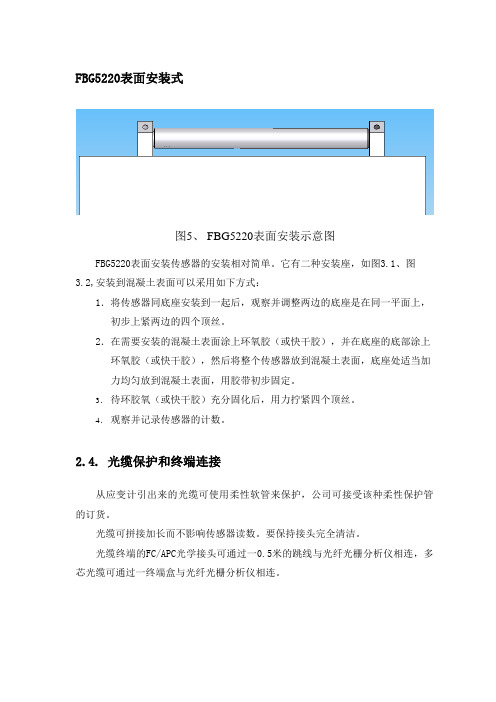
FBG5220表面安装式图5、 FBG5220表面安装示意图FBG5220表面安装传感器的安装相对简单。
它有二种安装座,如图3.1、图3.2,安装到混凝土表面可以采用如下方式:1.将传感器同底座安装到一起后,观察并调整两边的底座是在同一平面上,初步上紧两边的四个顶丝。
2.在需要安装的混凝土表面涂上环氧胶(或快干胶),并在底座的底部涂上环氧胶(或快干胶),然后将整个传感器放到混凝土表面,底座处适当加力均匀放到混凝土表面,用胶带初步固定。
3.待环胶氧(或快干胶)充分固化后,用力拧紧四个顶丝。
4.观察并记录传感器的计数。
2.4. 光缆保护和终端连接从应变计引出来的光缆可使用柔性软管来保护,公司可接受该种柔性保护管的订货。
光缆可拼接加长而不影响传感器读数。
要保持接头完全清洁。
光缆终端的FC/APC光学接头可通过一0.5米的跳线与光纤光栅分析仪相连,多芯光缆可通过一终端盒与光纤光栅分析仪相连。
3.读数光纤光栅分析仪是所有光纤光栅传感器获取读的仪器。
将连有光纤光栅传感器的光纤通过FC/APC光学接头即可接入光纤光栅分析仪,打开光纤光栅分析仪软件对传感器进行扫描即可读出传感器的当前波长值,光纤光栅分析仪的具体应用详见相关光纤光栅分析仪的使用说明书。
FBG-5210T(温补型)传感器内部都配有测读温度的光栅,随着温度变化,测温光栅的波长也变化,通过测温光栅波长的变化值可以得知温度的变化量。
FBG-5200(非温补型)传感器内部不配有测温度的光栅,但是可以在传感器外部单独放置一个温度传感器,以用作温补。
4.数据处理应变计波长读数转换成微应变可通过理论公式计算。
由于传感器本身存在温度影响系数 B,因此由于仪器温度影响而修正的混凝土总应变可由下面的公式计算出。
ε总 = k1(λ-λ0)+ B(λt1-λt0)上面的公式中包括混凝土中温度引起的应变,加上荷载变化引起的应变。
在无荷载区域温度引起的混凝土应变可由下面的公式计算出来;ε温度= (λt1-λt0) *αA*108其中αA代表混凝土温度膨胀系数,因此,下面公式用于计算仅仅因荷载变化引起的混凝土应变;ε=K(λ1-λ0)-B(λt1-λt0)K为应变计应变系数(με/nm)(取正值)B为温度修正系数,B= K+43.5(αA-αB)*106,单位取με/nm。
- 1、下载文档前请自行甄别文档内容的完整性,平台不提供额外的编辑、内容补充、找答案等附加服务。
- 2、"仅部分预览"的文档,不可在线预览部分如存在完整性等问题,可反馈申请退款(可完整预览的文档不适用该条件!)。
- 3、如文档侵犯您的权益,请联系客服反馈,我们会尽快为您处理(人工客服工作时间:9:00-18:30)。
Agilent 53220A/53230A
350 MHz Universal Frequency Counter/Timer
Product Reference CD-ROM. All product documentation, software, and examples are included on the Agilent 53210A/53220A/53230A Product Reference CD-ROM .
Quick Start Tutorial
Copyright © 2011 Agilent Technologies, Inc.
Printed In Malaysia January 2011 E0111
53220-90005 Edition 2
4
Example: -log 1,000 readings
-displays the trend chart when logging is complete.
Open the Interactive IO window by clicking on the ‘Remote Control’ menu icon.
Enter commands from the counter’s SCPI command set using the ‘Command’ window. Query commands which include ‘?’ return data and can be sent using Send & Read . Commands which do not return data are sent using Send Command .
If prompted, click on ‘Enter Password’ to view the password protected page. When shipped from Agilent, there is no password protection.
Adjust the handle to the desired position:
To remove, see instructions on underside of handle.
3. Channel Selection
1 Watt Max into 50
Displays help topics which can be selected using the rotary knob. Press and hold any function key or softkey to display help for that key or feature. configuration softkeys:
Use the ‘Trigger’ key to select the trigger configuration softkeys (source, readings per trigger, delay), or to issue a manual trigger.
Tip : numeric values can also be entered using the “shifted” numeric keys.
Use the ‘Math’ key to view the math functions available through the
softkeys. ‘All Math’ plus the selected function must be Press the ‘Trigger’ key to send a single trigger and start the measurements (Steps 2-4).
Use the ‘Graph’ and related softkeys to select a trend chart or enable a
histogram for graphical representations of the measurements.
Example: -trend chart of 1,000 readings
Use the ‘Trend Chart’ softkey to view a chart of the readings taken, or currently being taken.
Use the ‘Save Readings’ and ‘Export Readings’ softkeys within the trend chart or histogram menus to save data internally or to an external USB device.Reading Storage。