VS-5E_NSD 凸轮控制器VARICAM
智能位置传感器 SPTM-5V 系列说明书

Transmitter PRODUCT MANUAL PositionSmartSPTM-5V SERIESVERSION 1.01Contents1. Introduction (3)1.1 General information for the users (3)1.2 Manufacturer Warranty (3)1.3 Explosion Proof Warning (3)2. Product Description (4)2.1 General (4)2.2 Main Features and Functions (4)2.3 Label Description (4)2.4 Product Number (5)2.5 Product Specification (5)2.6 Parts and Assembly (6)2.7 Dimension – SPTM-5VL (7)2.8 Dimension – SPTM-5VR (7)3. Installation (8)3.1 Safety (8)3.2 SPTM-5VL Installation (8)3.3 SPTM-5VR Installation (9)4. Connection– Power (10)4.1 Safety (10)5. Adjustment (11)5.1 Setting Point Switch (11)5.2 Adjustment - Calibration (11)5.3 Adjustment – Potentiometer (11)6. Troubleshooting (12)1. Introduction1.1 General Information for the usersThank you for purchasing Young Tech Co., Ltd products. Each product has been fully inspected after its production to offer you the highest quality and reliable performance.Please read the product manual carefully prior to installing and commission the product.For the safety, it is important to follow the instructions in the manual. Young Tech Co., Ltd will not be responsible for any damages caused by user’s negligence.The manual should be provided to the end-user.Any modifications or repairs to the product may only be performed if expressed in this manual.The manual can be altered or revised without any prior notice. Any changes in product’s specification, design, and/or any components may not be printed immediatelybut until the following revision of the manual.The manual should not be duplicated or reproduced for any purpose without prior approval from Young Tech Co., Ltd, Gimpo-si, South Korea.Warranty1.2 ManufacturerFor the safety, it is important to follow the instructions in the manual. Manufacturer will not be responsible for any damages caused by user’s negligence.Manufacturer will not be responsible for any damages or accidents as a result of any alteration or modification of the product and its parts. If any alteration or modificationsare necessary, please contact Young Tech Co., Ltd directly.Manufacturer warrants the product from the date of original purchase of the product for one (1) year, except as otherwise stated.Manufacturer warranty will not cover products that have been subjected to abuse, accidents, alterations, modifications, tampering, negligence, misuse, faulty installation,lack of reasonable care, repair or service in any way that is not contemplated in thedocumentation for the product, or if the model or serial number has been altered,tampered with, defaced or removed; damages that occurs in shipment, due to act ofGod, failure due to power surge, or cosmetic damage. Improper or incorrectlyperformed maintenance will void this limited warranty.For detailed warranty information, please contact Young Tech Co., Ltd – South Korea.1.3 Explosion Proof WarningPlease ensure the unit is being used and installed within the explosion proof certified environment.SPTM-5V series explosion proof grades are Ex ia IIC T6.Certified ambient temperature is -20’C ~ 60’C. The product should be used in certifiedambient temperature. If the field is not explosion proof area and does not requireexplosion proof, the product can be used in temperature range of -40’C ~ 85’C. LCDoperation temperature range is –30’C ~ 85’C.Barrier must be installed with below specificationUi =28V, li =47mA, Pi =437mA, Li =0.3μH, Ci = 56.5nFThe product must be grounded according to explosion proof procedure.2. Product Description2.1 GeneralSPTM-5V series is 2 wire type transmitter with in-built micro-processor which transmits DC 4~20mA signal according to changes in valve or damper position.2.2 Main Features and FunctionsDesigned to be Ex ia IIC T6 explosion proof grades.Economical price and long product life time.Very easy and simple calibration.LCD displays current output signal.Description2.3 LabelFig. 1: SPTM-5V Body LabelA. Model Number: Indicates model number.B. Explosion Proof: Indicates certified explosion proof grade.C. Input.: Indicates input rotation angleD. Output: Indicates output signal rangeE. Lot No.: Indicates unique lot number** SPTM-5V series’ KCs certification conforms Ministry of Employment and Labor announcement article No. 2010-36.2.4 ProductNumber2.5 ProductSpecificationModel SPTM-5VL SPTM-5VR Input Type 2 WireInput Signal0 ~ 30 degrees 0 ~ 90 degreesOutput Signal 4 ~ 20mA DCLoad Resistance Max.600 Ω / 28V DCSupply Voltage9 ~ 28V DCNoise Range50mV p.p.Conduit Entry PF 1/2 (G 1/2)Enclosure IP 67Explosion Proof Ex ia IIC T6 (KCs)Ambient Temp.Operating: -40’C ~ 85’C Explosion Proof: -20’C ~ 60’C LCD Operating: -30 ~ 85’CLinearity ± 1% F.S. Hysteresis0.2% F.S Sensitivity ± 0.2% F.S. Material Aluminum Diecasting Weight 0.6 kgAssemblyand2.6 Parts2.7 Dimension – SPTM-5VL2.8 Dimension – SPTM-5VR3. Installation3.1 SafetyWhen installing a unit, please ensure to read and follow safety instructions.Check unit’s specification and ensure to use as specified.Follow other explosion proof procedures and safety precautions.Use bypass valve or other supportive equipment to avoid entire system “shut down”.Make sure all input and supply pressure to valve, actuator, and other related devices must be turned off.Installation3.2 SPTM-5VL1. Proper bracket must be made in order to adapt SPTM-5V on the actuator yoke.Please consider following important points when a bracket is being designed.- SPTM-5V feedback lever must be parallel to the ground at 50% of the valve stroke.- Feedback lever connection with the pin of the actuator clamp should be installed in such a way that the valve stroke length coincides with the corresponding figure of“mm marked on the feedback lever. Improper setting may cause poor linearity.2. Assemble the SPTM-5V with the bracket made in previousstep by fastening the bolts. Please refer to the backside ofthe SPTM-5V for size of the bolts. The standard bolt size isM8 x 1.25P.3. Attach SPTM-5V with the bracket to the actuator yoke – DONOT TIGHTEN COMPLETELY.4. Connect SPTM-5V’s feedback lever to the actuator clamp. The hole gap on thefeedback lever is 6.5mm. The connection pins outer diameter should be less than6.3mm.5. Connect supply pressure to the actuator temporarily. Supply enough supply pressure tothe actuator in order to position the actuator clamp at 50% of the total valve stroke.6. Insert connection pin into the feedback lever. The pin should be inserted when theactuator clamp is at 50% of the total valve stroke.7. Check if the feedback lever is parallel to the ground at 50% of thevalve stroke. If it is not parallel, adjust the bracket or feedback linkbar to make parallel. Improper installation may cause poorlinearity.8. Check the valve stroke. The stroke marks are indicated on the feedback lever.Position the connection pin at the number on the feedback lever which corresponds tothe desired valve stroke. To adjust, mover the bracket or the connection pin or both.9. After installing the SPTM-5v, operate the valve from 0% to100% stroke by using direct air to the actuator. On both 0%and 100%, the feedback lever should not touch the leverstopper, which is located on the backside of SPTM-5V. If thefeedback lever touches the stopper, SPTM-5V should beinstalled further away from the yoke.Installation3.3 SPTM-5VR1. Please refer to SPTM-5VL installation section for important note for bracket design.2. There are two types of the lever – standard and NAMUR type.4. Connection – Power4.1 SafetyWhen installing a unit, please ensure to read and follow safety instructions.When installing in hazardous and explosive gas area, conduit tube or pressure-proof packing union must be used.Please use ring-type rug to protect against vibration or any other external impact.Please use twisted cable with conductor section are 1.25mm2 and that is suitable for 600V (complying to the conductor table of NEC Article 310.) The outer diameter of thecable should be between 6.35 ~ 10mm. Use shield wire to protect against electro-magnetic field and noise.Please do not install the cable near high noise equipments, such as high-capacity transformer or motor.4.25. Adjustment5.1 Setting Point SwitchSPTM-5V series can be calibrated in 2 or 5 points setting.a) 2 Point Setting:By setting minimum and maximum points <0% and 100% of valve stroke>, in-bb) 5 Point SettingBy setting 5 points <0%, 25%, 50%, 75%, and 100%> the outputs can be set accordingly.5.2 Adjustment - Calibrationa) Input 4mA signal to the positioner to move the valve stroke to the 4mA position.b) After the valve reaches at the 4mA position, press “4mA button for 3-4 seconds. Thelamp will be lighted, and this indicates that 4mA outputfeedback position has been calibrated.c) Please repeat above step for 8mA, 12mA, 16mA, and20mA for 5 point setting. For 2 point setting, repeatabove step for 20mA only.5.3 Adjustment – PotentiometerPotentiometer is designed to output 12mA signal when the feedback lever is at 50% position.In case of dislocation of the potentiometer, please follow below procedure to re-set thepotentiometer.● Power must be turned off before adjusting potentiometer.● Please be cautious when adjusting potentiometer.● Please make sure that there is no remaining circuit on the PCB.● Please do not use excessive force when disconnecting potentiometer from the PCB.1. Locate the potentiometer under the PCB. Disconnect from the PCB. Please do not useexcessive force.2. Unfasten lock screw which locks the potentiometer gear and take out potentiometer bodyfrom the lag-gear.3. Fix the feedback lever at 50% position and measure resistance level by connecting twoprobes out of three inlets.4. Rotate pinion gear until resistance vale is about 5KΩ.5. After setting the resistance value, rotate stopper to the normal position an fasten the lockscrew.6. Reconnect potentiometer to the PCB and reinstall PCB onto SPTM-5V body.SPTM-5VR6. Troubleshooting1) SPTM-5V shows no output signal.A. Check actual input signal to SPTM-5V.B. Check power connection and + / - poles.2) Input signal value to the positioner and output signal value from SPTM-5V differsdramatically.A. Check input signal value and supply voltage. Insufficient voltage can affect input signalvalue.B. Check the installation of the positioner. If the positioner is installed improperly, pleaserefer to the positioner’s manual and re-install the positioner.C. Set the positioner’s zero and span. Inaccurate zero and span setting can lower theaccuracy and linearity.D. Check the installation of the position transmitter. If SPTM-5V is installed improperly,then refer to the manual and re-install.3) Sudden changes in SPTM-5V’s output signal value.A. Please make sure that SPTM-5V’s lever is placed at 50% point. If not, SPTM-5Vneeds to be re-installed and adjusted to be placed at the 50% point.B. Adjust the potentiometer. Potentiometer’s load resistance is 10KΩ, and it should beready at the 50% point.Manufacturer:Young Tech Co., Ltd#3022, Hagun-ri, Yangchon-myeonKimpo-si, Kyeonggi-do, 415-843South KoreaTel: +82-31-986-8545Fax: +82-31-986-2683Email: **********.krCopyright © Young Tech Co., Ltd. All Rights Reserved.。
正运动 VPLC710-I5-ETH5 视觉运动控制一体机 用户手册说明书

运动控制器提供丰富的接口,具有优良的运动控制性能,可以满足各种项目的扩展需求。
本手册介绍了产品的安装、接线、接口定义和操作说明等相关内容。
本手册版权归深圳市正运动技术有限公司所有,在未经本公司书面授权的情况下,任何人不得翻印、翻译和抄袭本手册中的任何内容。
前述行为均将构成对本公司手册版权之侵犯,本司将依法追究其法律责任。
涉及设备软件方面的详细资料以及每个指令的介绍和例程,请参阅Basic 编程手册或PC 函数库编程手册。
本手册中的信息资料仅供参考。
由于改进设计和功能等原因,正运动公司保留对本资料的最终解释权!内容如有更改,恕不另行通知!调试机器要注意安全!请务必在机器中设计有效的安全保护装置,并在软件中加入出错处理程序,否则所造成的损失,本公司没有义务或责任对此负责。
为了保证产品安全、正常、有效的使用,请您务必在安装、使用产品前仔细阅读本产品手册。
产品型号:VPLC710-I5系列机器视觉运动控制一体机用户手册文件名 版本号 版本(更改)说明更新日期 更改人 用户手册V1.0 1. 用户手册发布2023/6/19xcx前言更新记录● 本章对正确使用本产品所需关注的安全注意事项进行说明。
在使用本产品之前,请先阅读使用说明并正确理解安全注意事项的相关信息。
● 本产品应在符合设计规格要求的环境下使用,否则可能导致设备损坏,或者人员受伤,因未遵守相关规定引发的功能异常或部件损坏等不在产品质量保证范围之内。
● 因未遵守本手册的内容、违规操作产品引发的人身安全事故、财产损失等,我司将不承担任何法律责任。
按等级可分为“危险”、“注意”。
如果没有按要求操作,可能会导致中度伤害、轻伤及设备损伤的情况。
请妥善保管本指南以备需要时阅读,并请务必将本手册交给最终用户。
安装危险◆ 控制器拆卸时,系统使用的外部供应电源全部断开后再进行操作,否则可能造成设备误操作或损坏设备;◆ 禁止在以下场合使用:有灰尘、油烟、导电性尘埃、腐蚀性气体、可燃性气体的场所;暴露于高温、结露、风雨的场合;有振动、冲击的场合;电击、火灾、误操作也会导致产品损坏和恶化。
HYD CNC Technology CO.,LTD XPTHC-5 弧压等离子高度控制器说明书

HYD CNC Technology CO.,LTDTel:+86-755-26625800Fax:+86-755-26729960XPTHC-5Arc Voltage Plasma Height ControllerShenZhen HongYuDa CNC Technology CO.,LTD Please read this manual fully before useSAFETY:◆Please read this manual fully before use XPTHC-5◆DO NOT open cabinet of THC unless trained technician.◆DO NOT adjust the sealed resister.◆Turn off Powersupply if when THC is unused.◆DO NOT put liquid on THC.◆Attention Anti-dust work,DO NOT let metal dust into THC.Installation Note:◆Power supply:AC24V or DC24V◆Please offer the enough power supply:usually,25W motor,the current couldn’t beless than3A,the AC24V transformer couldn’t be less than50W.Power supply=2*motor’s power+10W◆GND Must follow THC instruction,GND resister≤4Ω。
◆UP/DOWN on THC must be same to Z-axis Lifter◆To avoid interference,follow cables please use shield cable(connection betweenCNC controller and THC,to motor,to voltage divider,to IHS card),especially thecable from THC to voltage divider,please use shield twisted pair cable,and shieldnet connected at THC side.◆Please don’t install the THC near by heat source,the normally work temperaturerange is-10℃~60℃.◆The plasma raw arc couldn’t connect to the THC directly,must connect to thevoltage divider correctly.To Customer:◆We only supply to re-seller as CNC cutting machine manufacturer,engineeringcompany…end-user please contact our local distributor for product supplying.◆We offer technical support to all distributors and users of our product.。
奥的斯DCSS5门机调试说明书
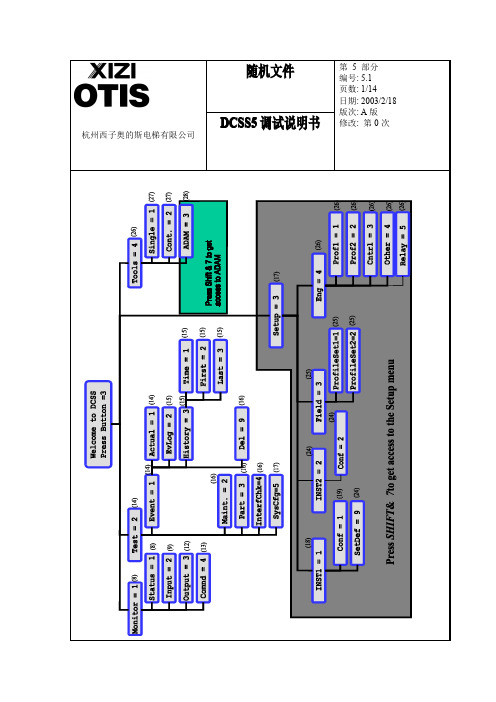
`杭州西子奥的斯电梯有限公司杭州西子奥的斯电梯有限公司`随机文件第5部分编号:5.2页数:2/14日期:2003/2/18版次:A 版修改:第0次DCSS5调试说明书一.自学习过程:(分Step1和Step2)Step1:W elcome to DCSS Press Button=3↓按“3”键Monitor=1Test=2Setup=3Tools=4↓按“3”键(为了得到SETUP 菜单,请按shift &7)Inst1=1Inst2=2Field=3Eng=4↓按“1”键Config=1SetDef=9↓按“1”键>Motor:DO2000Motor:HSDS↓按<GO ON/GO BACK>键,<ENTER>选择马达的类型。
>Door:TLD Door:CO↓选择开门的型式为中分或双折,TLD 为双折门,CO 为中分门杭州西子奥的斯电梯有限公司编号:5.3页数:3/14日期:2003/2/18版次:A版修改:第0次DCSS5调试说明书>Doorwidth:[mm]00900mm>——↓选择开门的宽度,<ENTER>>Encoder:DO2000Encoder:HSDS>↓<GO ON/GO BACK>>Encoder:user defined>↓选择编码器的类型,<ENTER>Step2:1.感觉测试:Sense TestPrep Sense TestPlease wait!Door is opening?<1>YES<0>NO↓观察门的移动并回答,如果门完全打开,它又开始关门Door is closingPlease wait!↓门完全关闭,又问Door is closed?<1>YES<0>NO回答问题杭州西子奥的斯电梯有限公司编号:5.4页数:4/14日期:2003/2/18版次:A版修改:第0次DCSS5调试说明书2.学习门的宽度:Learn DOORWAY编码器积累了开关门过程的脉冲来描述门的宽度。
凸轮控制器

一、凸轮控制器的结构凸轮控制器是一种大型手动控制电器,是起重机上重要的电气操作设备之一,用以直接操作与控制电动机的正反转、调速、起动与停止。
应用凸轮控制器控制电动机控制电路简单,维修方便,广泛用于中小型起重机的平移机构和小型起重机提升机构的控制中。
图8-4为凸轮控制器的结构原理图。
凸轮控制器从外部看,由机械结构、电气结构、防护结构等三部分组成。
其中手轮、转轴、凸轮、杠杆、弹簧、定位棘轮为机械结构。
触头、接线柱和联板等为电气结构。
而上下盖板、外罩及灭弧罩等为防护结构。
当转轴在手轮扳动下转动时,固定在轴上的凸轮同轴一起转动,当凸轮的凸起部位顶住滚子时,便将动触点与静触点分开;当转轴带动凸轮转动到凸轮凹处与滚子相对时,动触点在弹簧作用下,使动静触点紧密接触,从而实现触点接通与断开的目的。
在方轴上可以叠装不同形状的凸轮块,以使一系列动触点按预先安排的顺序接通与断开。
将这些触点接到电动机电路中,便可实现控制电动机的目的。
(a)结构外形图 (b)动作原理示意图图8-4 凸轮控制器结构示意图二、凸轮控制器的型号与主要技术参数常用的国产凸轮控制器有KT10、KT12、KT14、KT16等系列,以及KTJ1-50/1、KTJ1-50/5、KTJ1-80/1等型号。
凸轮控制器的型号及意义为:凸轮控制器按重复短时工作制设计,其JC=25%。
KT14系列凸轮控制器的主要技术参数见表,其中KT14-25J/1、KT14-60J/1型可用于同时控制两台绕线转子三相异步电动机,并带有控制定子电路的触点;KT14-25J/3型可用于控制一台笼型三相异步电动机的正反转;KT14-60J/4型可用于同时控制两台绕线转子三相异步电动机,定子电路由接触器控制。
表8-1 KT14系列凸轮控制器的主要技术参数图8-5所示为采用凸轮控制器控制的10t桥式起重机小车控制电路。
凸轮控制器控制电路的特点是原理图以其圆柱表面的展开图来表示。
由图8-5可见,凸轮控制器有编号为1~12的12对触点,以竖画的细实线表示;而凸轮控制器的操作手轮右旋(控制电动机正转)和左旋(控制电动机反转)各有5个档位,加上一个中间位置(称为“零位”)共有11个档位,用横画的细虚线表示;每对触点在各档位是否接通,则以在横竖线交点处的黑圆点表示。
西门子 NXGPro+ 控制系统手册_操作手册说明书
3.4
单元通讯的协议 ............................................................................................................ 36
3.5
NXGpro+ 高级安全 .......................................................................................................37
3.2
功率拓扑 ......................................................................................................................34
3.3
控制系统概述 ...............................................................................................................35
NXGPro+ 控制系统手册
NXGPro+ 控制系统手册
操作手册
AC
A5E50491925J
安全性信息
1
安全注意事项
2
控制系统简介
3
NXGPro+ 控制系统简介
4
硬件用户界面说明
5
参数配置/地址
6
运行控制系统
7
高级的操作功能
8
软件用户界面
9
运行软件
10
故障和报警检修
11
锐捷锐捷Am'D轻量肾形碳纤维车床说明书

V5 21/3/2020/ 13The Am’D lightweight asymmetrical carabiner is made of aluminum. It has a D shape particularly suited for connection to diverse equipment such as descenders or positioning lanyards. Its fluid interior design and Keylock system facilitatehandling. The Am’D carabiner is available in three locking systems: automatic TRIACT-LOCK or BALL-LOCK system, or the manual SCREW-LOCK system. Am'D may be used with a CAPTIV positioning bar to favor loading of the carabiner along the major axis, to limit the risk of it flipping and to keep it integrated with the device.The Am'D carabiner has an asymmetrical D shape that is ideal for attaching equipment such as descenders orpositioning lanyards. Use of the CAPTIV positioning bar favors loading of the carabiner along the major axis, limits its flipping and keeps it attached to the device or lanyard.Fluid interior design of Am'D carabiners limits the risk of having a catch point and facilitates rotation of the carabiner.The Am'D has an Hcross-section that ensures an optimal strength/weight ratio and protects the markings from abrasion.To facilitate equipment checks,SCREW-LOCK manual locking carabiners have a red band that is visible only when the carabiner is not locked.Universe Professional Type Verticality Category Connectors SubcategoryLight carabinersShort Description Lightweight asymmetrical carabinerSelling Points• D shape is particularly suited for connection to equipment such as descenders or positioning lanyards• Aluminum carabiner is light, reducing the weight of equipment the worker at height needs to carry• May be used with a CAPTIV positioning bar to favor loading of the carabiner along the major axis, to limit the risk of itflipping and to keep it integrated with the device• Easier handling:- fluid interior design limits the risk of having a catch point and facilitates rotation of the carabiner- Keylock system to avoid any involuntary snagging of the carabiner• H-shaped cross-section:- ensures an improved strength-to-weight ratio- protects markings from abrasion• Available in three different locking systems:- TRIACT-LOCK: automatic locking with triple-action gate opening- BALL-LOCK: automatic locking with triple-action gate opening, with lock indicator- SCREW-LOCK: the manual screw-lock with red band provides a visual warning when the carabiner is unlocked• Also available in black (TRIACT-LOCK and SCREW-LOCK versions) and gold (TRIACT-LOCK and BALL-LOCK versions) Specification• Material(s): aluminum• Certification(s): CE EN 362, EAC, NFPA 1983 Technical UseSpecifications by referenceAccessory(ies)CAPTIV Related product(s)I’D® SRIGGRILLON。
机器人及二次开发平台

• 客户可在IPC的Windows环境下开发自有软件– 专属HMI– Vision 图像处理– 产业加值软件– 中央监控(可基于WebAccess) – …
-二次开发平台
专用机构型式 , 因机构的位置姿态需要特别的算法 , 可自行将各种位置姿态依照算法转换为各轴的坐标 , 透过API函式传入RC2000中 , 并搭配RC2000宏读取传入的信息 ,进行实时运动控制。
EtherCAT,M-II及RTEX
内建Real-time PLC软件
数字通讯伺服
提供EtherCAT界面 , 硬
广泛应用于各式机器人
件扩充更加弹性
支持G/M码指令
亦可应用于机器或自动化
内建Real-time PLC软
的多轴控制
件与MACRO
Robot IPC ARC 7系列
ARC7 系列
ARC5 系列-机器人控制器脉冲型
应用领域伺服总线脉冲轴数屏幕
特征应用领域 伺服总线
ARC3系列 设备二次开发弹性平台
多轴运动控制系统方案
多轴运动控制系统方案EtherCAT/RTEX/MII (三选一) 无无 最大6伺服+2步进
可应用产业- IPC处理专用机构算法
专用机构 算法
可应用产业- IPC处理视觉辨识影像撷取
机器人前端安装视觉相机 , 以教 导方式调整机器人位置姿态并记 录该点位。运行时 , 由IPC软件直接通知机 器人移动到记录的点位 , 再进行 拍照与辨识。
视觉辨识传输运动位置
运动控制
应用软件画面(客户可自行开发)文件传输页面 G/M code运行画面 I/O 画面表 XYZ坐标的画面
• 内建六关节机器人算法 、 空间坐标转换功能• 支持空间直线 、 圆弧过渡、三点圆弧 、 圆心圆弧等功能 , 简化路径编辑• 工具校正实现旋转刀具功能• 坐标系校正功能• 提供复合路径的工艺设定(弧焊)
- 1、下载文档前请自行甄别文档内容的完整性,平台不提供额外的编辑、内容补充、找答案等附加服务。
- 2、"仅部分预览"的文档,不可在线预览部分如存在完整性等问题,可反馈申请退款(可完整预览的文档不适用该条件!)。
- 3、如文档侵犯您的权益,请联系客服反馈,我们会尽快为您处理(人工客服工作时间:9:00-18:30)。
CAUTION may also result in serious
damage or injury. Be sure to follow the all instructions accompanied by the symbol.
CAUTION
- Do not step on the controller or place heavy objects on the controller; otherwise, it will cause injury.
- Do not block the exhaust port or allow any foreign matter to enter the controller; otherwise, it will cause fire or unit failure.
Thank you very much for purchasing our product. Before operating this product, be sure to carefully read this manual so that you may fully understand the product, safety instructions and precautions.
3. Transport
CAUTION - Do not hold the cable or shaft of ABSOCODER sensor during
transport; otherwise, it will cause injury or controller malfunction.
4. Installation
- Be sure to use the specified combination of the ABSOCODER sensor, controller and sensor cable; otherwise, it may cause fire or controller malfunction.
- Be sure to use the controller and the ABSOCODER sensor in the environment designated by the general specifications in the manual. Failure to do so may result in electric shock, fire, malfunction or unit failure.
- Please submit this manual to the operators actually involved in operation. - Please keep this manual in a handy place.
Signal Words Safety precautions in this guide are classified into DANGER and CAUTION.
- Be sure to connect all cables correctly; otherwise, it may cause injury or controller malfunction.
- Be sure to firmly connect the external I/O connectors and sensor connectors; otherwise, it may cause incorrect inputs and outputs or injury.
- Be sure to secure the controller and ABSOCODER sensor with the provided brackets; otherwise, it may cause malfunction, injury, or drop.
- Be sure to secure the specified distance between the main body and the control panel or other equipments; otherwise, it may cause malfunction.
5. Wiring
DANGER
- Be sure to secure the terminal block firmly; otherwise, it may have risk of fire.
- Be sure to mount the terminal cover provided with the controller, before supplying the power, starting operation after the installation, and wiring; otherwise, it may cause electric shock.
Graphic Symbols Symbol
Meaning
Indicates prohibited items.
Indicates items that must be performed to.
Application Limitation
This product is not designed to be used under any situation affecting human life. When you are considering to use this product for special purposes such as medical equipment, aerospace equipment, nuclear power control systems, traffic systems, and etc., please consult with NSD.
- Connect the grounding terminal of the controller; otherwise, it may case electric shock or malfunction.
CAUTION
- Do not use the controller in the following palces; water splashes, the atmosphere of the corrosion, the atmosphere of the flammable vapor, and the side of the combustibility. Doing so may result in fire or the controller may become faulty.
6. Operation
CAUTION
- Do not change the controller's function switch settings during the operation; otherwise, it will cause injury.
- Do not approach the machine after instantaneous power failure has been recovered. Doing so may result in injury if the machine starts abruptly, it will cause injury.
2. Storage
CAUTION
- Do not store the controller in a place exposed to water, or toxic gas and liquid.
- Be sure to store the controller in designed temperature and humidity range, and do not exposed to direct sunlight. - Be sure to consult with NSD when the controller is stored for long periods.
1. Handling Precautions
DANGER
- Do not touch components inside of the controller; otherwise, it will cause electric shock.
- Do not damage the cable by applying excessive load, placing heavy objects on it, or clamping; otherwise, it will cause electric shock or fire.
CAUTION - Be sure to keep the sensor cable, control cable, and communication
cable at least 300 mm away from the main circuit and power line; otherwise it may cause injury or malfunction.
- Be sure to conduct independent trial runs for the controller before mounting the controller to the machine; otherwise, it may cause injury.
- When an error occur, be sure to eliminate the cause, ensure safety, and reset the error before restarting operation; otherwise, it may cause injury.