ARROW箭牌LED照明产品介绍手册2014
泛光灯产品说明

具有防护功能的LED泛光灯
产品说明
产品详细描述:
* 灯体采用环保加厚铝材, 表面打磨后经过喷塑处理, 外表美观, 抗腐蚀力强
* 散热器采用一体化加厚铝材设计, 背后荆条式利用空气对流设计, 有效提高散热效果, 保障光源寿命;
* 支架采用加厚U型板材, 固定采用加大不锈钢螺丝固定, 高强度固定, 确保灯具安装稳固不易损坏;
* 反光器采用高纯铝材质, 表面阳极氧化后镀膜处理, 反光效率高达93%以上;
* 透光罩采用优质钢化玻璃面罩, 透光率高, 照射光线均匀;
* 出线孔口采用进口硅胶密封圈和不锈钢出线头, 整灯防护等级达IP65;
* 后背独立电源和与光源灯体分离, 有效提高散热效果和避免光源热量传导到电源导致电源顺坏;
* 电源盒、灯体面盖贴合部位采用硅胶密封圈, 有效防止渗水而引起整灯顺坏, 保证整灯使用寿命;
应用场所:
广场照明、机场、码头、车站中杆灯、高杆灯照明、体育场照明、广告招牌、十字路口照明、公园景观照明等。
产品展示:。
Whelen M6 Series LED 尾烟灯头产品说明书
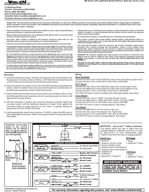
©2008 Whelen Engineering Company Inc.Form No. 14233F (103019)M6 Series LED Lighthead (Brake/Tail/Turn, Back-Up,Arrow, Turn)For warranty information regarding this product, visit /warranty1. Steady2. Signal-Alert™Steady B/T/T Model 1. Steady 2. Signal-Alert™SteadyTURN Model ARROW Model 1. Steady On 2. Sequence (150 fpm) to Solid 3. Sequence (80 fpm) to Solid 4. Sequence (Fast) to Solid-Steady On 5. Sequence (Slow) to Solid-Steady On 6. SingleFlash 757. ModuFlash™8. Signal-Alert™to Steady On Mounting:ing the dimensions below,mark the mounting and wire hole locations onto the proposed mounting surface.Drill two,.250"diameter mounting holes and a.625"(minimum)wire access hole into the mounting surface.2.Place the gasket into position on the rear of the M6assembly (see gasket note below).Insert the slotted hole screw grommet through the mounting holes on the M6/Gasket assembly so that it is flush with the lens.3.Feed the M6wires through the wire access hole in the mounting surface.Press the M6/Gasket/Grommet assembly onto its mounting location so that it is flat against the mounting surface.4.With the assembly in position and using the hardware provided,tighten the mounting screws until the lighthead assembly is drawn firmly against the mounting surface.A torque value of 12in-lb.(max.)is typically required to achieve this.DO NOT OVER TIGHTEN!ing appropriately sized wires (minimum 18AWG),extend the M6wires to their designated connections.Refer to the diagram below for wiring and fusing information.Safety First: This document provides all the necessary information to allow your Whelen product to be properly and safely installed. Before beginning the installation and/or operation of your new product, the installation technician and operator must read this manual completely. Important information is contained herein that could prevent serious injury or damage.•Proper installation of this product requires the installer to have a good understanding of automotive electronics,systems and procedures.•Whelen Engineering requires the use of waterproof butt splices and/or connectors if that connector could be exposed to moisture.•Any holes,either created or utilized by this product,should be made both air-and watertight using a sealant recommended by your vehicle manufacturer.•Failure to use specified installation parts and/or hardware will void the product warranty!•If mounting this product requires drilling holes,the installer MUST be sure that no vehicle components or other vital parts could be damaged by the drilling process.Check both sides of the mounting surface before drilling begins.Also de-burr any holes and remove any metal shards or remnants.Install grommets into all wire passage holes.•Do not install this product or route any wires in the deployment area of your air bag.Equipment mounted or located in the air bag deployment area will damage or reduce the effectiveness of the air bag,or become a projectile that could cause serious personal injury or death.Refer to your vehicle owner's manual for the air bag deployment area.The User/Installer assumes full responsibility to determine proper mounting location,based on providing ultimate safety to all passengers inside the vehicle.•For this product to operate at optimum efficiency,a good electrical connection to chassis ground must be made.The recommended procedure requires the product ground wire to be connected directly to the NEGATIVE (-)battery post.•If this product uses a remote device to activate or control this product,make sure that this control is located in an area that allows both the vehicle and the control to be operated safely in any driving condition.•Do not attempt to activate or control this device in a hazardous driving situation.•This product contains either strobe light(s),halogen light(s),high-intensity LEDs or a combination of these lights.Do not stare directly into these lights.Momentary blindness and/or eye damage could result.•Use only soap and water to clean the outer e of other chemicals could result in premature lens cracking (crazing)and discoloration.Lenses in this condition have significantly reduced effectiveness and should be replaced immediately.Inspect and operate this product regularly to confirm its proper operation and mounting condition.Do not use a pressure washer to clean this product.•WARNING!All customer supplied wires that connect to the positive (+)terminal of the battery must be sized to supply at least 125%of the maximum operating current and FUSED “at the battery”to carry that load.DO NOT USE CIRCUIT BREAKERS WITH THIS PRODUCT!•FAILURE TO FOLLOW THESE PRECAUTIONS AND INSTRUCTIONS COULD RESULT IN DAMAGE TO THE PRODUCT OR VEHICLE AND/OR SERIOUS INJURY TO YOU AND YOUR PASSENGERS!®ENGINEERING COMPANY INC.51 Winthrop RoadChester, Connecticut 06412-0684Phone: (860) 526-9504SalesEmail:*******************CanadianSales:************************CustomerService:*******************www..comWHITE/VIO -Scan-Lock™Pattern Selection:This feature allows the user to select from the available patterns. Lighthead must be on in order for Scan-Lock™to work.Momentarily apply +VBAT to the WHT/VIO wire to change patterns:Wiring:Back-Up ModelConnect the WHT wire to the POSITIVE output wire of the back-up light circuit.Connect the BLK (12V) or BLK/WHT (24V) wire to GROUND.B/T/T ModelConnect the YEL wire to the POSITIVE output wire of brake light circuit.Connect the BRN wire to the POSITIVE output wire of the taillight circuit.Connect the WHT (12V) or WHT/BLK (24V) wire to GROUND.The WHT/VIO wire is used to configure the brake light display. See below.Arrow ModelConnect the YEL wire to +VBAT. Fuse this wire @ 3Amps.Connect the BRN wire to +VBAT with SPST switch. Fuse @ 3AMPS Connect the WHT(12V) or WHT/BLK (24V) wire to GROUND.The WHT/VIO wire is used to change patterns. See below.Turn ModelConnect the BRN wire to Vehicle Clearance light inputConnect the YEL wire to the vehicles Turn Signal wire.Connect the BLK (12V) or BLK/WHT (24V) wire to GROUND.The WHT/VIO wire is used to change patterns. See below.Warnings to InstallersWhelen’s emergency vehicle warning devices must be properly mounted and wired in order to be effective and safe. Read and follow all of Whelen’s written instructions when installing or using this device. Emergency vehicles are often operated under high speed stressful conditions which must be accounted for when installing all emergency warning devices. Controls should be placed within convenient reach of the operator so that he can operate the system without taking his eyes off the roadway. Emergency warning devices can require high electrical voltages and/or currents. Properly protect and use caution around live electrical connections.Grounding or shorting of electrical connections can cause high current arcing, which can cause personal injury and/or vehicle damage, including fire. Many electronic devices used in emergency vehicles can create or be affected by electromagnetic interference.Therefore, after installation of any electronic device it is necessary to test all electronic equipment simultaneously to insure that they operate free of interference from other components within the vehicle. Never power emergency warning equipment from the same circuit or share the same grounding circuit with radio communication equipment.All devices should be mounted in accordance with the manufacturer’s instructions and securely fastened to vehicle elements of sufficient strength to withstand the forces applied to the device. Driver and/or passenger air bags (SRS) will affect the way equipment should be mounted.This device should be mounted by permanent installation and within the zones specified by the vehicle manufacturer, if any.Any device mounted in the deployment area of an air bag will damage or reduce the effectiveness of the air bag and may damage or dislodge the device. Installer must be sure that this device, its mounting hardware and electrical supply wiring does not interfere with the air bag or the SRS wiring or sensors. Mounting the unit inside the vehicle by a method other than permanent installation is not recommended as unit may become dislodged during swerving; sudden braking or collision. Failure to follow instructions can result in personal injury. Whelen assumes no liability for any loss resulting from the use of this warning device. PROPER INSTALLATION COMBINED WITH OPERATOR TRAINING IN THE PROPER USE OF EMERGENCY WARNING DEVICES IS ESSENTIAL TO INSURE THE SAFETY OF EMERGENCY PERSONNEL AND THE PUBLIC.Warnings to UsersWhelen’s emergency vehicle warning devices are intended to alert other operators and pedestrians to the presence and operation of emergency vehicles and personnel. However, the use of this or any other Whelen emergency warning device does not guarantee that you will have the right-of-way or that other drivers and pedestrians will properly heed an emergency warning signal. Never assume you have the right-of-way. It is your responsibility to proceed safely before entering an intersection, driving against traffic, responding at a high rate of speed, or walking on or around traffic lanes. Emergency vehicle warning devices should be tested on a daily basis to ensure that they operate properly. When in actual use, the operator must ensure that both visual and audible warnings are not blocked by vehicle components (i.e.: open trunks or compartment doors), people, vehicles, or other obstructions. It is the user’s responsibility to understand and obey all laws regarding emergency warning devices.The user should be familiar with all applicable laws and regulations prior to the use of any emergency vehicle warning device. Whelen’s audible warning devices are designed to project sound in a forward direction away from the vehicle occupants. However, because sustained periodic exposure to loud sounds can cause hearing loss, all audible warning devices should be installed and operated in accordance with the standards established by the National Fire Protection Association.。
LED照明产品说明书

LED lighting for hazardous areas Champ VMVL EMChamp VMVL LED with emergency back-up batteryCertifications and compliances:NEC & CEC• Class I, Division 2, Groups A, B, C, D • Class II, Division 1, Groups E, F , G • Class III • Class I, Zone 2• Simultaneous Presence •Wet Locations, Type 4X, IP66UL standards• UL 844 Hazardous (Classified)• UL1598 Luminaires, UL1598A Marine •UL924 (Emergency Luminaire)CSA standard•CSA C22.2 No. 137Lighting and back-up power is critical to any safety plan. That's why we've expanded our offering to include the Champ VMVL EM LED luminaire with an integrated battery backup.In the event of power loss or power interruption, Champ ® VMVL LED with built-in back-up powerprovides 90 minutes of emergency lighting to help keep your people safe and your plant running smoothly.Designed for maintenance-free illumination in egress and emergency lighting areas, the Champ VMVL is rated for indoor and outdoor emergency lighting in hazardous locations, such as manufacturing plants, heavy industrial, chemical, petrochemical facilities, platforms, loading docks and parking areas.VMVL -3 to 7VMVL -9 &11T emperature codes:All models –THDCurrent draw: 120-277 VAC Input power NominalBattery EM Battery EMElectrical ratings:*Maximum AC power draw by the charge controller is 4 Watts WeightEaton is a registered trademark.All other trademarks are property of their respective owners.Eaton’s Crouse-Hinds 1201 Wolf Street Syracuse, NY © 2022 EatonAll Rights Reserved Printed in USAPublication No. 5461-0322March 2022Ordering information20A20mm pendant3C1” ceiling25TW25mm wallAccessories(ordered separately)P3002Wire guardREPLACEMENT KITReplacement EM driver*Consult factory for lead time*Available with ceiling mounted modules only.Part number example: VMVL -3-W-2A-G-UNV1-EM1VMVL Champ VMVL, 3,000 lumens, 4000K warm white, ¾" pendant mount, Type V optics, wire guard, 100-277 VAC driver, emergency driver system, clear glass lens/ChampDimensions:。
ARROW系列方向幕帘探测器图文介绍
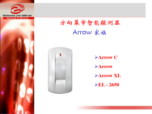
Arrow XL – 四源红外
四源 OI OI
Arrow XL – 步行测试
OI OI
外出/进入 红外束
IO = 红灯 OI = 绿灯
…步行测试注意事项
• 探测器供电后,须要90秒钟预热时间 • 进行步行测试前, 拿开报警延迟跳线,取消延迟时间
(对EL-2650无线红外,延迟时间最短也有1分钟)
Arrow XL & EL 2650 – 壁挂安装
不合法移动
从探测死角向探测区域移动会引起报警,所以有时在探 测器正下方移动,感觉没有方向分析功能。
Arrow XL & EL 2650 – 壁挂安装
带一定角度的倾斜安装,会消除探测死角,且不会失去 方向分析功能。
Arrow C – 典型安装
镜片支架 箭头遮挡片
有线 / 无线
有线
有线
有线
无线
红外传感器
双源
双源
四源
双源
方向分析技术
纯幕帘
温度补偿 单向补偿 单向补偿 单向补偿 双向补偿
Arrow 家族 – 常规概述
LED 颜色
Arrow Arrow – C Arrow XL EL –2650
报警 (不合法移动)
红
红
红
红
合法移动 报警延迟
无延迟 40 秒 2分 4分
Arrow C – 典型安装
Arrow C – 步行测试
• 离探测器几米的地方朝窗户方向移动 ,然后再回来, 红灯亮
• 一定要在离墙壁很近时才触发报警 • 如果想减少探测覆盖宽度,把调整刻度指向0以下
Arrow C – 透镜图案
壁挂安装
吸顶安装
Arrow XL – 透镜图案
蓝湾窄带LED高低浴室灯说明书

DAMPLOCFeatures• Configurations exceeding 168 lm/W • Standard low voltage dimming (0-10v)• Ideal for installations requiring daylight harvesting • PIR detection technology with advanced optics • Easy Bluetooth programming and configuration• Adjust sensor sensitivity to increase or decrease coverage area • Configurable daylight modes Featured Options• Adjustable cable suspension • Emergency lighting battery pack • Lenses available, see product keyMountingThis luminaire is specifically designed for suspended mount applications, including stem, chain & adjustable aircraft cable. Mounting kits available (ordered separately).ConstructionCNC fabricated, code gauge steel housing and ends, with integral ventilation slots and heat sinks.FinishWhite, pre-painted housing.ElectricalCSA/UL approved electronic components. Long life LEDs coupled with high efficiency drivers, provide quality illumination. Rated to deliver L80 performance for 50,000 hours at 40°C ambient temperature.ControlBluetooth low energy (BLE) enabled for sensor configuration through the Leviton Smart Sensor App. Advance optics included for 8-20ft low-mid bay and 20-40ft mid-high bay applications. Optional aisle-way masks are also included for both lenses. Programmable step dimming occupancy level (5-100%). Out-of-the box configuration features Auto-ON/Auto-OFF with 20-minute timeout, sensitivity set to high, and daylight harvesting enabled with auto calibration.Warranty5 year limited warranty. For complete warranty, click here:Product DescriptionThe Blue-Bay Narrow provides a 30 degree distibution angle for applications requiring narrow illumination. Thermally designed for high bay applications, this LED fixture is available in multiple lumen packages and various mounting options. It features a smart passive infrared (PIR) integrated sensor with advanced optics to provide an exceptional field of view for aisles with mounting heights from 8-40 ft.ApplicationsManufacturing areas, Retail stores and supermarkets, Warehouse and distribution (not for freezers and areas of high humidity or condensation).Approvals• Approved to CSA and UL standards.• Tested in accordance to IESNA LM-79.• Suitable for damp locations.• Complies with IECC, ASHRAE 90.1, and 2019 Title 24, Part 6 occupancy/vacancy sensing and • dimming requirements.DimensionsTop ViewP05(F41) Option shown hereEnd ViewOrder Key(ZLDUZ) - SchedulingLens OptionsNo lens is standard P05 Clear LensP05(F41) Clear Acrylic Lens with Blue RailsWiring Options V08** Flexible 6ft Cord Feed (Single Circuit Cord)V32 Wiring 2-Circuit CordV94(72WH) 5-Wire 6ft White Cord Feed (For DimmimgApplications)**** Not compatible with 347V or 480V. See ZLDUZ option.# If fixture is to be switched a 2 circuit cord V32 is advised** For pendant mounted applications only, not for use in surface mount applications.***Other finishes and cord lengths may be available, consult factory.Other options may be available, consult factory. Specifications and data subject to change without notice.EXAMPLE: LHBC248-LED840K240LUNVPerformance Scaling Factor240L - 24000300L - 30000180L - 18000210L - 21000240L - 24000300L - 30000360L - 36000420L - 42000480L - 48000600L - 60000_ _ _L*248424448C u s t o m L u m e n s*28000Lm Example:LHBC424-LED840K280LUNV-R50V96(ZLDIZ)Performance Data* Lumens/Watt and wattage is based on 25oCPhotometricsField of View Diagrams - Low Bay Sensor LensField of View Diagrams - High Bay Sensor Lens。
温润光电有限公司LED灯产品说明书
SpecificationClient Name:Client P/N:Wenrun P/N:LUE50333Date:Customer confirm Approved by Checked by Issued by尹亭亭Jiangsu Wenrun Optoelectronic Co. Rev:1Jiangsu Wenrun Optoelectronic Co.,LTD Rev:1Tel:*************Fax :*************Page 1of 7◆Features:●High speed response.●High reliability and long life.●Low power consumption.●Available in red,blue,white ,green,yellow colors.●Suitable for pulse operation.●This product doesn’t contain restriction Substance,comply ROHS standard.◆Descriptions:●The LED lamps are available with different colors,intensities,epoxy colors,etc.●The series specially designed for applications requiring higher brightness.●Superior performance in outdoor environment.◆Applications:●These lamp are widely used for various application.●Board for display.●Indication of all kinds.●Traffic Signal.◆Selection Guide:Part No.ChipLens Type Material Emitting Color LUE50333AlGaInPHigh Super RedWater Clear◆Package Dimensions:NOTES :1、All dimensions are in millimetres (mm).2、Tolerance is ±0.25mm(0.01”)unless otherwise noted.1.0min2.54typ0.5typ1.5max5.81.07.74.925.0min1.ANODE2.CATHODE21Jiangsu Wenrun Optoelectronic Co.,LTD Rev:1Tel:*************Fax :*************Page 2of 7◆Absolute Maximum Rating (Ta=25℃)ParameterSymbolHigh Super RedUnitPower Dissipation P d 70mW Pulse Forward Current I FP 100mA DC Forward Current I F 25mA Reverse Voltage V R 6V Electrostatic Discharge(HBM )ESD 2000V Operating Temperature Range Topr -40~+85℃Storage Temperature Range Tstg -40~+100℃Soldering TemperatureTsol260±5℃Notes :Soldering time ≤5seconds.I FP condition:pulse width ≤1ms ,duty cycle ≤1/10.Tsol condition :3mm for the base of the epoxy bulb.◆Electrical Optical Characteristics (Ta=25℃)Parameter Symbol High Super RedUnit Test Condition Min.Typ.Max.Luminous Intensity I V 4200--22500mcd I F =20mA Forward Voltage V F 1.8-- 2.3V I F =20mA Reverse Current I R ----50uA V R =6V Dominant Wavelength λd 618--628nm I F =20mA Peak Emission WavelengthλP --635--nm I F =20mA Viewing Angle2θ1/2--10--deg I F =20mA Spectral Line Half Width Δλ--20--nm I F =20mARecommond forward currentI F (rec)--20--mA--Notes:1.Tolerance of Luminous Intensity±10%2.Tolerance of Dominant Wavelength ±2nm3.Tolerance of Forward voltage ±0.05V4.Luminous Intensity is measured by WENRUN’s equipment on bare chips◆BIN rangeLuminous intensity(tolerance is±10%@I F=20mA):BIN CODE Min.(mcd)Max.(mcd)U42005500V55007000W70009000X900011500Y1150015000Z1500022500Dominant Wavelength(tolerance is±2nm@I F=20mA):BIN CODE Min.(nm)Max.(nm)K618620L620622M622625N625628Forward voltage(tolerance is±0.05V@I F=20mA):BIN CODE Min.(V)Max.(V)F 1.8 1.9G 1.9 2.0H 2.0 2.1J 2.1 2.2K 2.2 2.3Jiangsu Wenrun Optoelectronic Co.,LTD Rev:1 Tel:*************Fax:*************Page3of7Jiangsu Wenrun Optoelectronic Co.,LTD Rev:1Tel:*************Fax :*************Page 4of 7◆Reliability(1)Test Items and ConditionsNO Test Item Test ConditionsSample Ac/Re 1Temperature Cycle -40±5℃→25±5℃→100±5℃→25±5℃(30min ,5min ,30min ,5min)100Cycles 200/12High Temperature Storage Ta :100±5℃Test time=1000HRS(-24HRS,+72HRS)200/13High Temperature And High Humidity Working Ta :85±5℃,R H :85±5%,I F =20mA Test time=500HRS(-24HRS,+72HRS)200/14Low Temperature Storage Ta :-40±5℃Test time=1000HRS(-24HRS,+72HRS)200/15Operating Life Test Connect with a power I F =20mA Ta=Under room temperatureTest time=1000HRS(-24HRS,+72HRS)200/16Solder Resistance T.Sol=260±5℃one time Dwell Time=10±1Secs 200/17Thermal Shock-40±5℃→100±5℃(15min ,15min)100Cycles200/1(2)Criteria of judging the damageItem Symbol Test condition Criteria for judgement Min.Max.Forward voltage V F I F =20mA /U.S.L*1.1Reverse current I R V R =5V /15uA Luminous intensity I V I F =20mA L.S.L*0.7/Wave length λD/λPI F =20mA /U.S.L ±2nmAppearance/View checkNo mechanical damage*U.S.L:Upper standard levelL.S.L:Lower standard levelJiangsu Wenrun Optoelectronic Co.,LTD Rev:1Tel:*************Fax :*************Page 5of 7◆Typical Electro-Optical Characteristics Curves :Ta=25℃2.2 2.41.82.0Ta=25℃Relative Luminous Intensity Vs. WavelengthTa=25℃40302010Forward Current (mA)1.46800752550600560Wavelength (nm)520Forward Current Vs Ambient Temperature640Relative Luminous Intensity (%)10050Forward Current Vs Relative LuminosityForward Voltage (V)1.6Forward VoltageForward Current Vs.40502030175125150255075Relative Luminosity(%)1000010040301020Forward Current(mA)6020400Ambient Temperature Ta (°C)Relative Luminosity Vs Ambient Temperature80100Relative Luminosity (%)501002001506020400Ambient Temperature Ta (°C)80If=20mAForward Current (mA)105020020°0°-20°-10°10°50°70°60°40°1.080°90°0.500.5Radiation Angle-60°-70°1.0-80°-90°-50°-40°-30°30°Jiangsu Wenrun Optoelectronic Co.,LTD Rev:1Tel:*************Fax :*************Page 6of 7◆Label Form Specification◆Storage and application notices1、Storage1.Before opening package:the LEDs should be kept at 18-30℃,related humility:30-70%RH.They should beused out within 3moths;2.The internal and esterand boxes can not be contacted with ground to prevent absorption of moisture;3.No acid,alkali,salt,corrosive and explosive gas;away from sunlight and keep the environment clean;2、Application1.Do not use any unknown chemical liquid to clean LED,it will damage the LED resin surface;use the alcohol under the room temperature if necessary but less than 1min;2.When forming lead frame,the lead frame should be bent at a point at least 2mm from the base of epoxy.The forming should be done before soldering which can avoid epoxy’s broken and internal structure’s damage.Forming must be operated by the specific jig or the qualified operator to make sure the lead frame and distance are as same as the circuit board.Specific is shown as below,Mark:“○”means cor rect ,“×”means incorrect.3.Do not apply any bending stress to the base of the LED.The stress to the base may damage the internal connection which causes the electric character’s failure.Manufacturer Part No.QuantityClassing Marking Code Sealing Date (year-month-day)WENRUN OPTO.TYPE :LUE50333QUTY :xxxxPCS CODE :xxxxxxxx DATE :xxxxxx4.a.Soldering iron power:under30W;soldering temperature:295℃±5℃;soldering time:within3sec.(only1time);b.Soldering temperature in solder machine:250℃±10℃;soldering time:within5sec.c.Soldering temperature during wave soldering process:235℃±10℃,soldering time:within5sec.5.The LEDs should be soldered at the coordinated position on the PCB;the distance from soldering point toepoxy resin should be3mm at least.If the2nd soldering process required,3mins must be left to ensure the high temperature status can return to room temperature.But the recommended soldering time is only 1time in principle.6.If solder LEDs on one PCB by the soldering iron,do not solder the2lead frames of one LED at the sametime.7.Note of Electrical matter:1One-way conduction,LED does not allow the reverse driving;2LED is a kind of constant current component which can not be lighted by the constant voltage mode;a smaller voltage fluctuation can cause the large current fluctuation which causes the failure ofLED;Each LED should be drove under constant current mode if in a parallel circuit design,otherwise,the colour and brightness will be nonuniform;When the environmental temperature ris ing,the LED junction temperature will rise,internal resistance will decrease,so the current will be increased by the constant voltage power which short the life span;3If the brightness of lighting source can meet the requirement,we recommend using the driving current less than the rated current,in order to improve the product’s reliability;8.LED is a kind of electrostatic sensitive devises,anti-static measures have to be processed during storage and operation:1LED production workshop should lay anti-static floor and ground connection,the work table have to use the anti-static materials and cover a table mater with the surface resistance of106-109Ω2Production machine:REFLOW,SMT equipment,electric iron,test equipment;all the equipments must be well grounded,and the grounding alternating current impedance should be less than1.0Ω.A fan need to be installed on the equipments and production processes that easy to generate staticelectricity;the operators must wear anti-static clothing,shoes,wristband,and gloves,etc.in theprocess;3LEDs must be contained in the anti-static box,and all the package material should be the anti-static materials;9.The details electronic characters can refer to our product specification.◆Notes:1、Above specification may be changed without notice.We will reserve authority on material change for above specification.2、When using this product,please observe the absolute maximum ratings and the instructions for the specification sheets.We assume no responsibility for any damage resulting from use of the product which does not comply with the instructions included in the specification sheets.Jiangsu Wenrun Optoelectronic Co.,LTD Rev:1 Tel:*************Fax:*************Page7of7。
CITIZEN LED灯包产品说明书:CLL020-1202A1-503M1A2
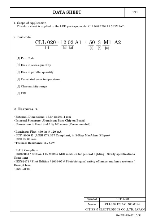
AnodeMarking 1Cathode(Tc Measurement Point) Marking 2Marking 1 : Serial No.Marking 2 : 12 02 50 M16. Reliability(1)Datails of the tests(2)Judgement Criteria of Failure for Reliability Test(Ta=25C)U defines the upper limit of the specified characteristics. S defines the initial value.Note : Measurement shall be taken between 2 hours and 24 hours, and the test pieces should be return to the normal ambient conditions after the completion of each test.Symbol CITILEDNameCLL020-1202A1-503M1A2>U X 1.1<S X 0.85I F =120mA Forward Voltage Total Luminous Flux85 C, 85 %RH for 500 hours -40 C × 30 minutes – 100 C × 30 minutes, 100 cycleThermal Shock Test I F =120mAVF ΦvTest ItemTest ConditionSymbol Measuring ConditionJudgement Criteria for FailureMeasuring Item Continuous Operation TestLow Temperature Storage Test High Temperature Storage Test Moisture-proof Test Ta=25 C, I F =120 mA× 1000 hours(with Al-fin)I Fmax =240 mA Tjmax=150C × 1000 hours(with Al-fin)-40 C × 1000 hours 100 C × 1000 hours< Example of indication label >1. TYPE e.g. CLL020-1202A1-503M1A22. P.No. (Cutomer's P/N) e.g. 50008-010-*******M13. Lot No.- First and second letter: Last digit of the year e.g. 11 : year 2011 - Third letter: Production month e.g. 8 : AugustNote: October, November and December are designated - Forth letter: CE's control number e.g. 50354. QuantitySymbol Product 54 pcs/tray< Packing figure >CUSTOMERPASSCITIZEN ELECTRONICSTYPE P. NO Lot No Q'ty : CLL020-******-*******: ******: *******: ***---(1)---(2)---(3)---(4)3. Precautions for product assembly-When the LED package is attached to the heat sink by M3 screws, please be careful not to applytoo much stress to the LED package. For example, fix the screws firmly after temporarily fixing them.-Attachment to heat sink conditions such as tightening torque for screws should be optimized in accordance with the specifications for heat sinks. In addition, asperity or burrs harms the thermal connection between Recommended installation screw pitch13.513.57. Lighting at a low currentA minimum current value of lighting of all dice is 10mA.When a minimum current is applied, LED dice may look different in their brightness due tothe individual difference of the LED element, and it is not a failed product.8. Please be aware that this product should not come into contact with any other partsin assembled status.9. Drive circuit- A constant current circuit is recommended as a drive circuit.And when two or more LED packages are connected, the series connectionbetween each package is recommended.- Please design a circuit that prevents any reverse voltage (excess current) from beingapplied to this product instantaneously when the circuit is ON or OFF.10. Heat generation- As this product is designed with consideration of the heat release property of module,a heat release design is required to use this product efficiently.Please ensure that heat generation is not in excess of the absolute maximum rating.(Refer to 4-1 Performance)- Factors responsible for an increase in temperature include heat generation attributed toambient temperature conditions or power dissipation. Thus, drive conditions should betaken into consideration, depending on ambient temperature (Ta).11. Recommended soldering condition (This product is not adaptable to reflow process)- Manual soldering- Soldering shall be implemented using a soldering bit of 40W or less with a temperature350°C or less within 3.5 seconds for one land.(Recommended condition in a case of lead-free solder condition)- No external force shall be applied to resin part during soldering.- Next process of soldering should be carried out after the product has returned to ambient temperature. - For soldering correction- Regarding soldering correction, above conditions shall be used.- Contacts number of soldering bit should be within twice for each terminal as a correction.* Citizen Electronics cannot guarantee if usage exceeds this recommended conditions.Please use it after sufficient verification is carried out on your own risk if necessary.Symbol CITILED12. Eye Safety- The International Electrical Commission (IEC) published in 2006 IEC 62471”2006 Photobiological safety oflamps and lamp systems” which includes LEDs within its scope.When sorting single LEDs according to IEC 62471, most white LEDs can be classified as belonging to either Exempt Group or Risk Group 1.- However, Optical characteristics of LEDs such as radiant flux, spectrum and light distribution are factors that affect the risk group determination of the LED, and especially a high-power LED,that emits light containing blue wavelengths, may have properties equivalent to those of Risk Group 2. - Great care should be taken when directly viewing an LED that is driven at high current,has multiple uses as a module or when focusing the light with optical instruments,as these actions may greatly increase the hazard to your eyes.- It is recommended to regard the evaluation of stand-alone LED packages as a reference and to evaluate the customer's final product.13. The use of Class 2 power supply is assumed for this product.14. If the product might to be used under the following conditions, the customer must evaluateits approproateness them. This product is not designed for use under the following conditions.in places where the product might:- get wet due to rain- suffer from damage caused by salt.- be exposed to corrosive gas such as Cl, H2S, NH3, SO2, Nox and so on.- be exposed to dust, fluid or oil.Symbol CITILED9. Precautions with regard to product use1. This document is provided for reference purposes only so that CITIZEN ELECTRONICS' products are used as intended. CITIZEN ELECTRONICS neither makes warranties or representations with respect to the accuracy or completeness of the information contained in this document nor grants any license to any intellectual property rights or any other rights of CITIZEN ELECTRONICS or any third party with respect to the information in this document.2. All information included in this document such as product data, diagrams, charts, is current as of the date this document is issued. Such information, however, is subject to change without any prior notice. Before purchasing or using any CITIZEN ELECTRONICS' products listed in this document, please confirm the latest product information with a CITIZEN ELECTRONICS' sales office, and formal specifications must be exchanged and signed by both parties prior to mass production.3. CITIZEN ELECTRONICS has used reasonable care in compiling the information included in this document, but CITIZEN ELECTRONICS assumes no liability whatsoever for any damages incurred as a result of errors or omissions in the information included in this document.4. Absent a written signed agreement, except as provided in the relevant terms and conditions of sale for product, and to the maximum extent allowable by law, CITIZEN ELECTRONICS assumes no liability whatsoever, including without limitation, indirect, consequential, special, or incidental damages or loss, including without limitation, loss of profits, loss of opportunities, business interruption and loss of data, and disclaims any and all express or implied warranties and conditions related to sale, use of product, or information, including warranties or conditions of merchantability, fitness for a particular purpose, accuracy of information, or no infringement.5. Though CITIZEN ELECTRONICS works continually to improve products' quality and reliability, products can malfunction or fail. Customers are responsible for complying with safety standards and for providing adequate designs and safeguards to minimize risk and avoid situations in which a malfunction or failure of a product could cause loss of human life, bodily injury or damage to property, including data loss or corruption. In addition, customers are also responsible for determining the appropriateness of use of any information contained in this document such as application cases not only with evaluating by their own but also by the entire system. CITIZEN ELECTRONICS assumes no liability for customers' product design or applications.6. Please contact CITIZEN ELECTRONICS' sales office if you have any questions regarding the information contained in this document, or if you have any other inquiries.CITIZEN Micro HumanTech is a registered trademark of Citizen Holding Co., Japan.CITILED is a registered trademark of CITIZEN ELECTRONICS CO., LTD. JapanCITIZEN ELECTRONICS CO.,LTD. JAPANDATA SHEET11/11Symbol CITILED Name CLL020-1202A1-503M1A2Ref.CE-P1467 10/11。
2016 Eaton 箭心购买指南:商业照明控制产品型号说明书

S E C T I O NUniversal phase selectable slide dimmersP-3Single-pole, 3-wireSUF7, 450W, 120V/AC P-3SUF7, 450W, 277V/AC P-3SUF7, 650W, 120V/AC P-3SUF7, 1000W, 277V/ACP-3Universal slide dimmers (Forward Phase-cut)P-3Single-pole, 3-wireSUT7, 450W, 120V/AC P-3SUT7, 600W, 277V/AC P-3SUT7, 720W, 120V/AC P-3SUT7, 1000W, 277V/AC P-3 Decorator dimmersP-4Single-pole, 3-wireDF10P , 1200W, 120V/AC P-4DF10P , 1600W, 277V/AC P-4DCK1, Faceplate P-4Slide dimmersP-4Single-pole, 3-wireSF10P , 1200W, 120V/AC P-4SF10P , 1600W, 277V/ACP-4Wire leads – wall mount PIR with instinct (no neutral)P-5Single-pole, 3-wire1000 sq. ft. major motion (92.2 sq. m), 180 PIR P-5300 sq. ft. major motion (27.9 sq. m), 180 PIR P-5Wire leads – wall mount PIR (no neutral)P-5Single-pole, 3-wire1000 sq. ft. major motion (92.2 sq. m), 180 PIR P-5300 sq. ft. major motion (27.9 sq. m), 180 PIR P-5Wire leads – wall mount dual tech with instinct (neutral required)P-5Single-pole, 3-wire1000 sq. ft. major motion (92.2 sq. m), 180 PIR P-5300 sq. ft. major motion (27.9 sq. m), 180 PIR P-5Electronic specificationsP-5Single-pole, 3-wire120V/AC @ 60Hz P-5Occupancy & vacancy dimmer sensorsP-6Single-pole, 3-wireRating1200W, 120V/ACNEMA 5-15P-62200W, 277V/AC NEMA 5-20P-6Commercial ceiling sensorsP-7Coverage, Field of viewFrequencyDT , 500 sq. ft., One way(180°)40 kHz P-7DT , 1000 sq. ft., Two way (360°)32 kHz P-7DT , 2000 sq. ft., Two way (360°)32 kHz P-7DT , 2000 sq. ft., Two way (360°)32 kHz P-7DT , 2000 sq. ft., Two way (360°)32 kHz P-7PIR, 500 sq. ft., (360°)–P-7PIR, 1500 sq. ft., (360°)–P-7PIR, 500 sq. ft., (360°)–P-7PIR, 500 sq. ft., (360°)–P-7PIR, 1500 sq. ft., (360°)–P-7PIR, 1500 sq. ft., (360°)–P-7U, 500 sq. ft., One way (180°)40 kHz P-7U, 1000 sq. ft., Two way (360°)32 kHz P-7U, 2000 sq. ft., Two way (360°)32 kHz P-7U, 2000 sq. ft., Two way (360°)32 kHz P-7U, 2000 sq. ft., Two way (360°)32 kHz P-7DT , 1200 sq. ft., Wide angle (120°)–P-7P , 1200 sq. ft., Wide angle (120°)–P-7P , 90 linear. ft., (180°)–P-7MicroSet STEM accessory –P-7Heavy duty switch pack–P-7T able of contentsCommercial Lighting Controls0-10V Dimmer SensorColor matched, tamper resistantlensDimming control provided withhorizontal dim/bright barGreen LED indicates motiondetectionSelectable time delay withmanual OFFCode Compliance: Solutions to help comply with energy codes including ASHRAE 90.1 & California Title 200-10V Dimmer Sensor - OS10D7, VS10D7The ultimate solution to reduce energy andi nstallation cost.Replace a switchpack, sensor & 0-10V dimmerwith O NE Eaton 0-10V Dimmer Sensor.Universal Slide Dimmer - SUT7The high wattage solution for dimming the mostcommon lighting loads.Universal Slide Dimmer ratings are among theindustry’s leading wattage ratings for dimmableLEDs & CFLs.323Eaton’s sensors and dimmers are cost -effective solutions for commercial lighting c ontrol installationsWith Eaton’s solutions you have the right control every time. SECTIONPUniversal dimmersUniversal phase selectable slide dimmersDescriptionCompatible lamp typesRating Watt V/ACColor suffixCatalog no.Universal phase selectable slide dimmer LED/CFL/FLR450 450120 277BK, GY, LA, V, W SUF7-__INC/HAL/ELV 6501000120277BK, GY, LA, V, WProduct descriptionSingle pole & 3-wayDimmable LED/CFL/FLR ; 450W, 120V/AC; 450W, 277V/AC INC/HAL/EL V ; 650W, 120V/AC; 1000W, 277V/AC Design featuresUniversal phase selectable slide dimmers• Select between forward and reverse phase cut dimming for the mostoptimal dimming compatibility • Dual rated for 120/277V/AC• Adjustable low-end trimming for increased lamp compatibility• No de-rating for LED/CFL loads in multi-gang applications• Integrated full slide control for easy, precise operation• Ideal for commercial and residential applications • Neutral required for installation • Fits standard decorator wallplates • Do Not use with MLV loadsSUF7Universal slide dimmersDescriptionCompatible lamp typesRating Watt V/ACColor suffixCatalog no.Universal slide dimmer (forward phase-cut)LED/CFL/FLR 450600120277BK, GY, LA, V, W SUT7-__INC/HAL/MLV/ELV7201000120277BK, GY, LA, V, WSUT7Product descriptionSingle pole & 3-wayDimmable LED/CFL/FLR ; 450W, 120V/AC; 600W, 277V/AC INC/HAL/ML V/EL V ; 720W, 120V/AC; 1000W, 277V/AC Design featuresUniversal slide dimmers (Forward Phase-cut)• Universal dimming of most common lighting loads (phase-cut)• Dual rated for 120/277V/AC• Adjustable low-end trimming for increased lamp compatibility• No de-rating for LED/CFL loads in multi-gang applications• Integrated full slide control for easy, precise operation• Ideal for commercial and residential applications • No neutral required for installation •Fits standard decorator wallplatesColor ordering informationFor ordering devices, include Catalog no. followed by the color suffix: BK (Black), GY (Gray), LA (Light Almond), V (Ivory), W (White)Compliances, specifications and availability are subject to change without notice.DF10PProduct descriptionSingle pole & 3-way 1200W @ 120V/AC 1600W @ 277V/AC0-10VDC FLR and LED ballasts Design featuresDecorator & slide dimmers• Preset feature allows user to return to previous light level when turning lights ON • Integrated full-slide control for easy, precise operation• Can be wired as single pole or 3-way• Neutral is not required for installation of device •Adjustable high-level trim setting for optimal lamp compatibility•Decorator dimmers have removable faceplates to allow for color changes and each package includes three colors• Color change kits (DF10P only)• Compatible with dimmable LED and fluorescent 0-10V ballasts•Compatible with any decorator wallplate or screwless decorator wallplateDescriptionCompatible lamp typesRating Watt V/ACColor suffixCatalog no.Decorator dimmer Single pole/3-way preset 0-10VDC LED/FLR 12001600120277C2, C4, C5 DF10P-__Color change faceplate for DF10P–––B, BK, GY, LA,V, WDCK1-__Decorator dimmersDescriptionCompatible lamp typesRatingWatt V/ACColor suffixCatalog no.Slide dimmer Single pole/3-way preset0-10VDC LED/FLR 12001600120277B, BK, GY, LA, V, W SF10P-__Slide dimmersSF10PColor ordering informationFor ordering devices, include Catalog no. followed by the color suffix: B (Brown), BK (Black), GY (Gray), LA (Light Almond),V (Ivory), W (White), C2 (Color Change Kit: LA, W, V), C4 (Color Change Kit: BK, W, V), C5 (Color Change Kit: BK, W, GY),LA (Light Almond), W (White),V (Ivory)BK (Black), W (White), V (Ivory)BK (Black), W (White), GY (Gray)Decorator & slide dimmersCompliances, specifications and availability are subject to change without notice.Commercial specification grade occupancy sensors features• Selectable automatic ON mode or manual ON mode • Convenient installation and test mode for set up •Adjustable built-in light level sensor for additional energy savings • Selectable time delay • California Title 24 compliant•For use with incandescent lamps, halogen fixtures, electronic and magnetic fluorescent ballasts, and electrical motor loads•Wallplate included with OSP10 & OSD10 models• Dual rated: 120V and 277V in the same unit • Single-pole or 3-way wiring•Manual OFF push button can be used in either automatic or manual mode • Reinforced lens is tamper-resistant •Zero-crossing switching technology to maximize relay life and ensure wall switch longevity•Fits standard size decorator wallplateElectronic specificationsCoverage areaWire leads – wall mount PIR with instinct (no neutral)Coverage areaDescriptionColor suffixCatalog no.1000 sq. ft. major motion (92.2 sq. m)300 sq. ft. minor motion (27.9 sq. m)180º passive infrared single relay occupancy sensing wall switchBK, GY, LA, V, W OSP10-__180º passive infrared dual relay occupancy sensing wall switchBK, GY, LA, V, WOSP10D-__cULus listedWire leads – wall mount PIR (no neutral)Coverage areaDescriptionColor suffixCatalog no.1000 sq. ft. major motion (92.2 sq. m)300 sq. ft. minor motion (27.9 sq. m)180º passive infrared single relay occupancy sensing wall switchBK, GY, LA, V, W OSP10M-__cULus listedWire leads – wall mount dual tech with instinct (neutral required)Coverage areaDescriptionColor suffixCatalog no.1000 sq. ft. major motion (92.2 sq. m)300 sq. ft. minor motion (27.9 sq. m)180º dual tech single relay occupancy sensing wall switchBK, GY, LA, V, W OSD10N-__180º dual tech dual relay occupancy sensing wall switchBK, GY, LA, V, WOSD10DN-__cULus listedOSP10OSP10MOSD10DNColor ordering information:For ordering devices, include Catalog no. followed by the Color suffix: BK (Black), GY (Gray), LA (Light Almond), V (Ivory), W (White)(Black)(Gray)(Lt. Almond)(Ivory)(White)Commercial occupancy sensorsWire leads-wall mountOSP10, OSP10D, OSD10N, OSD10DN OSP10MPower requirements:120/277VAC @ 60Hz Power requirements:120/277VAC @ 60HzMaximum load:Incandescent/halogen: @120V: 6.7A, 800W, 60Hz Fluorescent:@120V: 10A, 1200W, 60Hz @277V: 9.8A, 2700W, 60Hz Motor:@120V: 1/4 HP @125 V/ACMaximum load:Incandescent/halogen:@120VAC, 60Hz: 15A, 1800WMagnetic ballast (Fluorescent, MLV): @120VAC, 60Hz: 15A, 1800VA @277VAC, 60Hz: 8A, 2200VA Electronic ballast(Fluorescent, CFL/LED/ELV lighting): @120VAC, 60Hz: 10A, 1200VA @277VAC, 60Hz: 8A, 2200VA Motor:@120VAC, 60Hz; 1/2 HpMinor Motion, IR Major Motion, IRMaximum coverage area may vary somewhat according to room shape and the presence of obstacles.36’Testing & code compliance: Listed to UL508 (UL244A for OSP10M), California Title 24 Energy Code compliant, RoHS Compliant Material characteristics: Flammability meets UL94 requirements; V0 rated, Temperature Rating: 0ºC to 40ºC (32ºF to 104ºF)Compliances, specifications and availability are subject to change without notice.OS10D7Product descriptionSingle pole & 3-way10A @ 120V/AC8A @ 277V/AC0-10VDC FLR and LED ballastsDesign features• 3 in 1 device combining dimming, switchingand motion sensing• Digital PIR sensor for occupancy(Auto ON/Auto OFF) and vacancy(Manual ON/Auto OFF) sensing• Provides 180 degree field of view and1000 sq. ft. of major motion coverage• Full-range preset dimming control providedwith horizontal dim/bright bar• Green LED indicates motion detection• Selectable ambient light override in occupancysensor models• Selectable time delay of 15 seconds (Test mode,changes to 2 minutes after 2 minutesof powering up), 5 minutes (factory default),15 minutes and 20 minutes• Occupancy Sensor version can be toggledbetween Auto ON/Auto OFF or Manual ON/AutoOFF• Vacancy sensor meets California Title 20(VS10D7 only)• Compatible with any decorator wallplate orscrewless decorator wallplate• Neutral required for installation of device DescriptionCompatiblelamp typesRatingWatt V/AC Color suffix Catalog no.Occupancy sensor & dimmer with LEDsingle pole/3-way preset0-10VDCLED/FLR12002200120277BK, GY, LA, V, W OS10D7-__Vacancy sensor & dimmer with LEDsingle pole/3-way preset0-10VDCLED/FLR12002200120277BK, GY, LA, V, W VS10D7-__Occupancy & vacancy dimmer sensorsColor ordering informationFor ordering devices, include Catalog no. followed by the color suffix: BK (Black), GY (Gray), LA (Light Almond), V (Ivory), W (White) (Black)(Gray)(Light Almond)(Ivory)(White)Occupancy & vacancy dimmer sensors0-10V Dimmer sensorsCompliances, specifications and availability are subject to change without notice.Commercial ceiling sensorsCommercial ceiling sensorsAHAC-U-2000-MVAHAWC-DT -120W•MicroSet self-adjusting time delay and sensitivity•Products tested to NEMA WD 7 - 2011 Occupancy Motion Sensors Standard• Built-in light level sensor • Selectable walk-through mode •California Title 20 CompliantDesign featuresProduct descriptionCoverage: 500, 1000, 2,000 sq ft Frequency: 40, 32kHzTechnology: Dual technology, Passive infrared (PIR), UltrasonicCommercial ceiling sensorsColor information(White)DescriptionCoverageField of viewFrequency FeaturesCatalog no.MicroSet dual tech low voltage500 sq. ft. One way (180°)40 kHz — AHAC-DT-05011,000 sq. ft.Two way (360°)32 kHz — AHAC-DT-10002,000 sq. ft.Two way (360°)32 kHz —AHAC-DT-2000MicroSet dual tech line voltage2,000 sq. ft.Two way (360°)32 kHz Dual relay with daylight sensorAHAC-DT-2000-DMV 2,000 sq. ft.Two way (360°)32 kHz With daylight sensor AHAC-DT-2000-MV MicroSet PIR low voltage500 sq. ft.(360°)—— AHAC-P-05001,500 sq. ft. (360°)——AHAC-P-1500MicroSet PIR line voltage500 sq. ft. (360°)—With daylight sensor AHAC-P-0500-MV 500 sq. ft.(360°)—Dual relay with daylight sensorAHAC-P-0500-DMV 1,500 sq. ft.(360°)—With daylight sensor AHAC-P-1500-MV 1,500 sq. ft.(360°)—Dual relay with daylight sensor AHAC-P-1500-DMV MicroSet ultrasonic low voltage500 sq. ft.One way (180°)40 kHz — AHAC-U-05011,000 sq. ft.Two way (360°)32 kHz —AHAC-U-10002,000 sq. ft.Two way (360°)32 kHz Dual relay with daylight sensorAHAC-U-2000MicroSet ultrasonic line voltage 2,000 sq. ft.Two way (360°)32 kHz Dual relay with daylight sensorAHAC-U-2000-DMV 2,000 sq. ft.Two way (360°)32 kHzWith daylight sensor AHAC-U-2000-MV Dual tech wall/corner sensor1,200 sq. ft.Wide angle (120°)—— AHAWC-DT-120W Passive infrared wall/corner sensor 1,200 sq. ft.Wide angle (120°)—— AHAWC-P-120W 90 linear ft.(180°)—— AHAWC-P-009L-H MicroSet STEM accessory ————AHAC-STEM Heavy duty switch pack———Capable of switching up to 20AAHSP20-MVTechnologyDT = Dual TechP = Passive Infrared (PIR)U = UltrasonicCommercial ceilingsensors sample number:AHAC-DT -0501AHSP20-MVCompliances, specifications and availability are subject to change without notice.。