2014-31-Engine Brake Cam Lobe Optimization Using Coupled GT-POWER + Mechanical Hydraulic Simulation
Mastercam9.1后处理20141127-思图文

# 1 = Stop = output the "M00" stop code
# 2 = Ostop = output the "M01" optional stop code
# It is designed to support the features of Mastercam Mill V8.
#
# Following Misc. Integers are used:
#
# mi1 - Work coordinate system
# 0 = Reference return is generated and G92 with the
# the position of the rotary axis. This is the default setting.
#
#3 Axis Rotary (Polar)
# Polar positioning is offered in Mastercam 3 axis toolpaths through the
# 2 = WCS of G54, G55.... based on Mastercam settings.
#
# mi2 - Absolute or Incremental positioning at top level
# 0 = absolute
# 1 = incremental
# 'multi-axis' selection (i.e. Rotary 4 axis). All 5 axis paths are
ADAMS-CAR教程
目录表(续)
第9章 第 10 章
第 11 章
参数化
在 ADAMS/Car 中的参数化 生成硬点 生成构造坐标系 位置参数化 方向参数化
建立模板
模板综述 模板的拓扑关系 文件的构成 建立一个新的模板 部件的类型 刚体和弹性体(部件) 几何外形 连接方式 (约束和衬套) 弹簧 阻尼器 止挡和反向止挡 前束角(Toe)/外倾角(Camber)和悬挂参数数组 可调载荷 一些建议
如何得到帮助
ADAMS/Car 全部帮 助的索引/搜索
被选内容
浏览条目的 目录表
如何得到帮助
技术支持
欲找到各地区技术支持,可浏览: /support/contacts/index.cfm
欲查找服务协议,可浏览: /support/ prod_support/adams/ADM_02ZZZLT_T_SERL_HJ_R6.pdf
为什么要使用 ADAMS/Car?
通过共享模型和数据在各部门及产品供应商间提供桥梁
不同的部门可以在统一的数据库下工作,最大限度的减少数据损失。
Test lab
Engine
Advanced Engineering
Driveline
Chassis engineering
Body engineering
练习 3: 生成并调整子系统 曲线编辑器和特性文件编辑器
利用曲线编辑器和特性文件编辑器编制特性文件 特性文件种类 生成特性文件 特性文件编辑器 转换 TeimOrbit 格式文件为 XML格式文件 修改现有的特性文件 绘图 vs. 数表
练习 4: 使用曲线编辑器修改弹簧特性
输出配置文件
解决SolidWorks2012-2014无法安装Simulation,Motion等插件
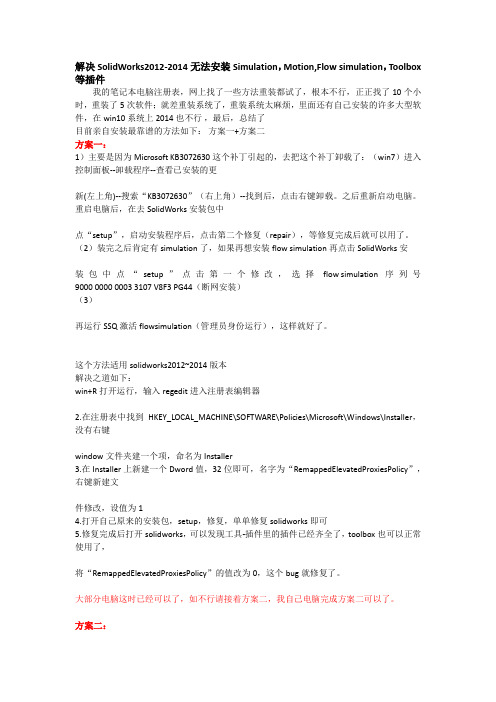
解决SolidWorks2012-2014无法安装Simulation,Motion,Flow simulation,Toolbox 等插件我的笔记本电脑注册表,网上找了一些方法重装都试了,根本不行,正正找了10个小时,重装了5次软件;就差重装系统了,重装系统太麻烦,里面还有自己安装的许多大型软件,在win10系统上2014也不行,最后,总结了目前亲自安装最靠谱的方法如下:方案一+方案二方案一:1)主要是因为Microsoft KB3072630这个补丁引起的,去把这个补丁卸载了:(win7)进入控制面板--卸载程序--查看已安装的更新(左上角)--搜索“KB3072630”(右上角)--找到后,点击右键卸载。
之后重新启动电脑。
重启电脑后,在去SolidWorks安装包中点“setup”,启动安装程序后,点击第二个修复(repair),等修复完成后就可以用了。
(2)装完之后肯定有simulation了,如果再想安装flow simulation再点击SolidWorks安装包中点“setup”点击第一个修改,选择flow simulation 序列号9000 0000 0003 3107 V8F3 PG44(断网安装)(3)再运行SSQ激活flowsimulation(管理员身份运行),这样就好了。
这个方法适用solidworks2012~2014版本解决之道如下:win+R打开运行,输入regedit进入注册表编辑器2.在注册表中找到HKEY_LOCAL_MACHINE\SOFTWARE\Policies\Microsoft\Windows\Installer,没有右键window文件夹建一个项,命名为Installer3.在Installer上新建一个Dword值,32位即可,名字为“RemappedElevatedProxiesPolicy”,右键新建文件修改,设值为14.打开自己原来的安装包,setup,修复,单单修复solidworks即可5.修复完成后打开solidworks,可以发现工具-插件里的插件已经齐全了,toolbox也可以正常使用了,将“RemappedElevatedProxiesPolicy”的值改为0,这个bug就修复了。
MITSUBISHI-FUSO FE车辆配置指南说明书

BODY BUILDER’S DRAWINGSANDSUPPORTING DATALIT. No. LTE07001-ASEP. 2007INTRODUCTIONThis book has been designed to provide information for body and equipment manufacturers who mount their products on MITSUBISHI-FUSO FE chassis.We believe that all the detailed information which is essential for that purpose is contained in this book, but if you require any additional data or information, please contact:MITSUBISHI FUSO TRUCK OF AMERICA, INC.2015 Center Square Road,Logan Township, NJ 08085(Phone : (856) 467-4500)The specifications and descriptions contined in this book are based on the latest product information at the time of publication, but since the design of MITSUBISHI-FUSO truck is continuously being improved, we must reserve the right to discontinue or change at any time without prior notice.COMPLIANCE WITH FEDERAL MOTOR VEHICLE SAFETY STANDARDSThe federal government has established Federal Motor Vehicle Safety Standards (FMVSS) for various categories of motor vehicles and motor vehicle equipment under the provisions of the National Traffic and Motor Vehicle Safety Act of 1966. The Act imposes important legal responsibilities on manufacturers, dealers, body builders and others engaged in the marketing of motor vehicles and motor vehicle equipment.Vehicles manufactured by Mitsubishi FUSO Truck & Bus Corporation (MFTBC) for the subsequent installation of commercial bodies are classified as incomplete vehicles. These vehicles fully comply with certain applicable Motor Vehicle Safety Standards, and partially (or do not) comply with others. They cannot be certified fully because certain components which are required for certification are not furnished. Under present federal regulations, vehicles completed from these units are required to meet all applicable standards in effect on the date of manufacture of the incomplete vehicle, the date of final completion, or date between those two dates, as determined by their final configuration.MFTBC incomplete vehicles carry in the glove box a document, as shown on the next page, that provides the vehicle types (truck) into which they may appropriately be completed, and the degree to which the incomplete vehicles comply with each of the standards in effect on the date of its manufacture. The completing manufacturer must certify compliance with all applicable standards, but may rely on MFTBC certification for those standards so indicated in the instructions for completing the vehicle document, provided that the instructions for completing the vehicle are followed. Questions may be directed to the Engineering or Service Department of MFTBC.Alterations, modifications, or additions to the vehicle which affect compliance with FMVSS are not covered by MFTBC certification and are the responsibility of the completing manufacturer. Likewise the completing manufacturer must assume responsibility for compliance with changes in federal requirements that occur after the manufacture of the incomplete vehicle by MFTBC, if he elects to certify compliance as of a later date.INCOMPLETE VEHICLE DOCUMENTDO NOT REMOVETHIS DOCUMENT MUST REMAIN WITH THIS VEHICLEUNTIL IT IS CERTIFIED AS A COMPLETE VEHICLEList of FMVSS and CMVSS applicable to MFTBC trucks with GVWR of more than 10,000 lbs. manufactured after Jan. 1, 2007 is shown below.FMVSS/CMVSS NO. TitleDisplaysand101 Controls102 Transmission Shift Lever Sequence,Starter Interlock and Transmission Braking Effect103 Windshield Defrosting and Defogging Systems104 Windshield Wiping and Washing Systems105 Hydraulic Brake SystemsHoses106 Brake108 Lamps, Reflective Devices and Associated Equipment111 RearviewMirrorsIdentification Number (CMVSS ONLY)115 Vehicle116 Motor Vehicle Brake Fluids119 New Pneumatic Tires for Vehicles other than Passenger Cars120 Tire Selection and Rims for Motor Vehicles other than Passenger CarsSystems124 AcceleratorControlMaterials205 Glazing206 Door Locks and Door Retention ComponentsSystems207 Seating208 Occupant Crash Protection209 Seat Belt Assemblies210 Seat Belt Assembly Anchorages302 Flammability of Interior Materials1100 Vehicle Emissions (CMVSS only)1106 Noise Emission (CMVSS only)In addition to the Incomplete Vehicle Document, a Safety conformanceLabel as shown to the right is affixed to all the vehicles when shippedfrom the factory. This label contains all the FMVSS numbers applicablenot only to chassis-cabs but also to completed vehicles if they arecompleted in accordance with the Incomplete Vehicle Document.This label is affixed to the door latch post of the left-hand side door.DO NOT COVER OVER WITH ANY OTHER LABEL.NOISE REGULATIONSThe U.S. Environmental Protection Agency (EPA) has established noise emission standards applicable to medium and heavy trucks in excess of 10,000 lbs. GVWR manufactured after January 1, 1988 (40 CFR §205.52), requiring that they must conform to an 80 dB (A) maximum noise level when tested pursuant to EPA’s test procedures.MFTBC trucks are built in conformance with EPA Noise Emission Standards. Modified or altered vehicles may increase in noise emissions; compliance with applicable noise standards are the responsibility of the subsequent stage manufacturer.A sample of Noise Emission Conformity Label is shown below. This label is affixed to all the vehicles when shipped from the factory.DO NOT COVER OVER WITH ANY OTHER LABEL.This label is affixed to the left-hand side door panel.PART IIDRAWINGS AND TECHNICAL DATATABLE OF CONTENTS1. LINE-UP CHART ....................................................................................................................................... II-1-12. TYPICAL BODY LENGTH ......................................................................................................................... II-2-13. CHASSIS CAB DRAWING ........................................................................................................................ II-3-13.1 Chassis cab drawing ........................................................................................................................ II-3-13.1.1 FE8!DDZ (automatic transmission) ...........................................................................................II-3-13.1.2 FE85DDZ (manual transmission) ................................................................................................ II-3-23.1.3 FE8!DEZ (automatic transmission) ...........................................................................................II-3-33.1.4 FE85DEZ (manual transmission) ................................................................................................ II-3-43.1.5 FE8!DGZ (automatic transmission) ...........................................................................................II-3-53.1.6 FE85DGZ (manual transmission) ................................................................................................ II-3-63.1.7 FE84DHW (automatic transmission) ........................................................................................... II-3-73.1.8 FE8!DJZ (automatic transmission) ............................................................................................II-3-83.1.9 FE85DJZ (manual transmission) ................................................................................................. II-3-93.1.10 FE85DKZ (automatic transmission) ............................................................................................ II-3-103.1.11 FE85DKZ (manual transmission) ................................................................................................ II-3-113.1.12 FG84DF6 (manual transmission) ................................................................................................ II-3-123.2 Cab front and rear view .................................................................................................................... II-3-134. CHASSIS FRAME ASSEMBLY ................................................................................................................. II-4-14.1 FE8!DDZ ........................................................................................................................................ II-4-14.2 FE8!DEZ ......................................................................................................................................... II-4-24.3 FE8!DGZ ........................................................................................................................................ II-4-34.4 FE8!DJZ ......................................................................................................................................... II-4-44.5 FE85DKZ .......................................................................................................................................... II-4-54.6 FE84DHW ........................................................................................................................................ II-4-64.7 FG84DF6 .......................................................................................................................................... II-4-75. CROSSMEMBER REAR VIEW ................................................................................................................. II-5-15.1 FE Series (Except FE84DHW) ......................................................................................................... II-5-15.2 FE84DHW ........................................................................................................................................ II-5-25.3 FG Series ......................................................................................................................................... II-5-36. FRAME SECTION MODULUS DIAGRAMS .............................................................................................. II-6-16.1 FE8!DDZ ........................................................................................................................................ II-6-16.2 FE8!DEZ ......................................................................................................................................... II-6-26.3 FE8!DGZ ........................................................................................................................................ II-6-36.4 FE8!DJZ ......................................................................................................................................... II-6-46.5 FE85DKZ .......................................................................................................................................... II-6-56.6 FE84DHW ........................................................................................................................................ II-6-66.7 FG84DF6 .......................................................................................................................................... II-6-77. FRAME HEIGHT ........................................................................................................................................ II-7-17.1 Tire radius ......................................................................................................................................... II-7-17.2 Front and rear springs ...................................................................................................................... II-7-27.2.1 FE83 ............................................................................................................................................ II-7-27.2.2 FE84 (Except FE84DHW) .......................................................................................................... II-7-37.2.3 FE84DHW ................................................................................................................................... II-7-47.2.4 FE85 ............................................................................................................................................ II-7-57.2.5 FG84 ........................................................................................................................................... II-7-67.3 Vehicle’s sprung weight .................................................................................................................... II-7-78. TIRE AND DISC WHEEL .......................................................................................................................... II-8-19. FRONT AXLE ............................................................................................................................................ II-9-110. REAR AXLE ............................................................................................................................................... II-10-111. REAR AXLE BOUNCE HEIGHT ............................................................................................................... II-11-112. FUEL TANK ............................................................................................................................................... II-12-112.1 FE Series .......................................................................................................................................... II-12-112.2 FE Series (Rear fuel tank) ................................................................................................................ II-12-312.3 FE Series (Spare fuel tank) .............................................................................................................. II-12-412.4 FG Series ......................................................................................................................................... II-12-513. BATTERY BOX .......................................................................................................................................... II-13-114. LICENSE PLATE LAMP ............................................................................................................................ II-14-115. REAR COMBINATION LAMP ................................................................................................................... II-15-116. BRAKES PIPING DIAGRAM ..................................................................................................................... II-16-116.1 FE83D, FE84D ................................................................................................................................. II-16-116.2 FE85D .............................................................................................................................................. II-16-216.3 FG84DF6 .......................................................................................................................................... II-16-317. PROPELLER SHAFT ................................................................................................................................ II-17-118. EXHAUST SYSTEM .................................................................................................................................. II-18-118.1 FE8!DDZ ........................................................................................................................................ II-18-118.2 FE8!DEZ ......................................................................................................................................... II-18-218.3 FE8!DGZ ........................................................................................................................................ II-18-318.4 FE8!DJZ, FE85DKZ ....................................................................................................................... II-18-418.5 FE84DHW ........................................................................................................................................ II-18-518.6 FG84DF6 .......................................................................................................................................... II-18-619. ELECTRIC CIRCUIT DIAGRAM ............................................................................................................... II-19-119.1 POWER, CHARGE AND GROUND CIRCUIT .................................................................................II-19-1POWER CIRCUIT ...............................................................................................................II-19-1RESERVE POWER CIRCUIT .............................................................................................II-19-13BATTERY CHARGING CIRCUIT ........................................................................................II-19-14GROUND ............................................................................................................................. II-19-1519.2 STARTING CIRCUIT ........................................................................................................................ II-19-32ENGINE STARTING CIRCUIT ............................................................................................II-19-32ENGINE PREHEATING CIRCUIT .......................................................................................II-19-3419.3 LIGHTING CIRCUIT ......................................................................................................................... II-19-36HEADLAMP CIRCUIT .........................................................................................................II-19-36DAYTIME RUNNING LIGHT CIRCUIT ...............................................................................II-19-37TAIL, CLEARANCE AND LICENSE PLATE LAMPS CIRCUIT ..........................................II-19-39STOP LAMP CIRCUIT ........................................................................................................ II-19-40TURN SIGNAL AND HAZARD LAMP CIRCUIT .................................................................II-19-42BACKUP LAMP CIRCUIT ...................................................................................................II-19-43CAB LAMP CIRCUIT ........................................................................................................... II-19-45ILLUMINATION LAMP CIRCUIT .........................................................................................II-19-46IDENTIFICATION LAMP AND SIDE MARKER LAMP CIRCUIT ........................................II-19-47VAN BODY DOME LIGHT CIRCUIT ...................................................................................II-19-4819.4 METER CLUSTER ........................................................................................................................... II-19-49METER CLUSTER INTERNAL CIRCUIT ...........................................................................II-19-49TACHOMETER CIRCUIT ....................................................................................................II-19-51SPEEDOMETER CIRCUIT .................................................................................................II-19-52FUEL GAUGE CIRCUIT ......................................................................................................II-19-53WATER TEMPERATURE GAUGE CIRCUIT .....................................................................II-19-5419.5 INDICATOR AND WARNING LAMP CIRCUIT ................................................................................II-19-55PARKING BRAKE INDICATOR CIRCUIT ..........................................................................II-19-55BRAKE WARNING CIRCUIT ..............................................................................................II-19-56ENGINE OIL LEVEL WARNING CIRCUIT .........................................................................II-19-58ENGINE OIL PRESSURE WARNING CIRCUIT .................................................................II-19-59OVERHEATING WARNING CIRCUIT ................................................................................II-19-60BRAKE PAD WARNING CIRCUIT ......................................................................................II-19-61CAB TILT WARNING CIRCUIT ...........................................................................................II-19-62FUEL FILTER WARNING CIRCUIT ....................................................................................II-19-63 19.6 CAB SIDE ELECTRICAL CIRCUIT .................................................................................................. II-19-64CIGARETTE LIGHTER CIRCUIT ........................................................................................II-19-64AUDIO CIRCUIT .................................................................................................................. II-19-65WIPER AND WASHER CIRCUIT ........................................................................................II-19-66HORN CIRCUIT .................................................................................................................. II-19-67AIR-CONDITIONER CIRCUIT ............................................................................................II-19-68POWER WINDOW AND CENTRAL DOOR LOCK CIRCUIT .............................................II-19-70MIRROR HEATER CIRCUIT ...............................................................................................II-19-71 19.7 CHASSIS SIDE ELECTRICAL CIRCUIT ......................................................................................... II-19-72EXHAUST BRAKE CIRCUIT ...............................................................................................II-19-72 19.8 ENGINE AND TRANSMISSION SIDE ELECTRICAL CIRCUIT ......................................................II-19-74TRANSMISSION POWER TAKE-OFF CIRCUIT ................................................................II-19-74 19.9 OTHER CIRCUIT ............................................................................................................................. II-19-75JOINT CONNECTOR (J/C) .................................................................................................II-19-75DIAGNOSIS SWITCH AND MEMORY CLEAR SWITCH ...................................................II-19-79 SYSTEM CIRCUIT .................................................................................................II-19-80 COMMONRAILSYSTEM CIRCUIT ..................................................................................................II-19-87 AUTOCRUISETRANSMISSION CIRCUIT ........................................................................................II-19-89 AUTOMATICSYSTEM CIRCUIT ......................................................................................... II-19-93 ANTI-LOCKBRAKEMFTA suggests the X-marked body length of each model because of stability, commerciality and reliability.Rear body dimensions shall not exceed 96” wide (outside) and 96” from top of frame to top of body without prior approval from MFTA Applications Group.Dimensions, Inch (mm) Body Length (ft) Vehicle ModelWB CA UCA CB CE OAL HG 1214 16 18114.6 93.9 86 7.9 158.5227.224.0DX(2,910) (2,385) (2,185)(200)(4,025)(5,771)(610)134.3 113.6 105.77.9 178.1246.924.0X XE(3,410) (2,885) (2,685)(200)(4,525)(6,271)(610)152.4 131.7 123.87.9 196.3265 24.0X XG(3,870) (3,345) (3,145)(200)(4,985)(6,731)(610)176 155.3 147.47.9 219.9288.624.0XJ(4,470) (3,945) (3,745)(200)(5,585)(7,331)(610)189.4 168.7 160.87.9 233.3302 24.0K(4,810) (4,285) (4,085)(200)(5,925)(7,671)(610)165.4 105.3 103.4 1.9 147.8254.326.6X1 X1 FE84D HW(4,200) (2,675) (2,626)(49) (3,753)(6,460)(675)138.2 116.9 108.58.5 158.0224.928.3FG84D FX1 X1(3,510) (2,970) (2,755)(215)(4,013)(5,713)(720)X1: NOT APPLICABLE TO REAR FUEL TANK Variations to this chart require prior approval from MFTA Applications Group.Selection of the correct model and wheelbase is dependent on many factors. This chart can serve only as a quick reference guide. It does not preclude the necessity of performing a complete weight distribution analysis, particularly when equipment such as lift gates, reefers or others are required.MFTA assumes no liability whatsoever for any damage(s) to person(s) or property caused by utilization of this chart. Selection of the correct model and wheelbase is solely the responsibility of the selling dealers and final stage manufacturer. All weight distribution calculations herein are based on water level loading and a cab-to-body clearance on above table. When selection of the correct model and wheelbase is made, carefully follow the requirements below;(a) Individual GAWR’s and GVWR’s must not be exceeded.(b) It is advisable that front axle loading ratio be 33% of total vehicle weight or more for vehicle stability.(c) The length of the rear overhang must comply with state and local regulations, if any.The center of gravity of the completed vehicle with a full load should not exceed 60” above ground level and must be located horizontally between the centerlines of the front and rear axles.5.1 FE Series (Except FE84DHW)(F R O N T ) (R E A R )(F R O N T ) (R E A R )(F R O N T )(R E A R )(F R O N T ) (R E A R )(R E A R )(F R O N T )(R E A R )。
Drivecon XR变频器说明书

danger. 7. High voltages are present in this device. Do not make any inspections
Drivecon Inc. reserves the right to alter or amend the above information without notice
Drivecon Inc.
3.7.1998 • DAHSM31
Service Manual
Page 2
CONTENTS
1 DESCRIPTION OF XR Series ..................................................................................................... 4 1.1 Functional description ......................................................................................................... 6 1.2 Motor control modes ........................................................................................................... 8 1.3 Control methods (= command modes) ................................................................................. 9 1.4 Mechanical brake control .................................................................................................. 14
Indradrive 系列 故障代码
Error MessagesF9001 Error internal function call.F9002 Error internal RTOS function callF9003 WatchdogF9004 Hardware trapF8000 Fatal hardware errorF8010 Autom. commutation: Max. motion range when moving back F8011 Commutation offset could not be determinedF8012 Autom. commutation: Max. motion rangeF8013 Automatic commutation: Current too lowF8014 Automatic commutation: OvercurrentF8015 Automatic commutation: TimeoutF8016 Automatic commutation: Iteration without resultF8017 Automatic commutation: Incorrect commutation adjustment F8018 Device overtemperature shutdownF8022 Enc. 1: Enc. signals incorr. (can be cleared in ph. 2) F8023 Error mechanical link of encoder or motor connectionF8025 Overvoltage in power sectionF8027 Safe torque off while drive enabledF8028 Overcurrent in power sectionF8030 Safe stop 1 while drive enabledF8042 Encoder 2 error: Signal amplitude incorrectF8057 Device overload shutdownF8060 Overcurrent in power sectionF8064 Interruption of motor phaseF8067 Synchronization PWM-Timer wrongF8069 +/-15Volt DC errorF8070 +24Volt DC errorF8076 Error in error angle loopF8078 Speed loop error.F8079 Velocity limit value exceededF8091 Power section defectiveF8100 Error when initializing the parameter handlingF8102 Error when initializing power sectionF8118 Invalid power section/firmware combinationF8120 Invalid control section/firmware combinationF8122 Control section defectiveF8129 Incorrect optional module firmwareF8130 Firmware of option 2 of safety technology defectiveF8133 Error when checking interrupting circuitsF8134 SBS: Fatal errorF8135 SMD: Velocity exceededF8140 Fatal CCD error.F8201 Safety command for basic initialization incorrectF8203 Safety technology configuration parameter invalidF8813 Connection error mains chokeF8830 Power section errorF8838 Overcurrent external braking resistorF7010 Safely-limited increment exceededF7011 Safely-monitored position, exceeded in pos. DirectionF7012 Safely-monitored position, exceeded in neg. DirectionF7013 Safely-limited speed exceededF7020 Safe maximum speed exceededF7021 Safely-limited position exceededF7030 Position window Safe stop 2 exceededF7031 Incorrect direction of motionF7040 Validation error parameterized - effective thresholdF7041 Actual position value validation errorF7042 Validation error of safe operation modeF7043 Error of output stage interlockF7050 Time for stopping process exceeded8.3.15 F7051 Safely-monitored deceleration exceeded (159)8.4 Travel Range Errors (F6xxx) (161)8.4.1 Behavior in the Case of Travel Range Errors (161)8.4.2 F6010 PLC Runtime Error (162)8.4.3 F6024 Maximum braking time exceeded (163)8.4.4 F6028 Position limit value exceeded (overflow) (164)8.4.5 F6029 Positive position limit exceeded (164)8.4.6 F6030 Negative position limit exceeded (165)8.4.7 F6034 Emergency-Stop (166)8.4.8 F6042 Both travel range limit switches activated (167)8.4.9 F6043 Positive travel range limit switch activated (167)8.4.10 F6044 Negative travel range limit switch activated (168)8.4.11 F6140 CCD slave error (emergency halt) (169)8.5 Interface Errors (F4xxx) (169)8.5.1 Behavior in the Case of Interface Errors (169)8.5.2 F4001 Sync telegram failure (170)8.5.3 F4002 RTD telegram failure (171)8.5.4 F4003 Invalid communication phase shutdown (172)8.5.5 F4004 Error during phase progression (172)8.5.6 F4005 Error during phase regression (173)8.5.7 F4006 Phase switching without ready signal (173)8.5.8 F4009 Bus failure (173)8.5.9 F4012 Incorrect I/O length (175)8.5.10 F4016 PLC double real-time channel failure (176)8.5.11 F4017 S-III: Incorrect sequence during phase switch (176)8.5.12 F4034 Emergency-Stop (177)8.5.13 F4140 CCD communication error (178)8.6 Non-Fatal Safety Technology Errors (F3xxx) (178)8.6.1 Behavior in the Case of Non-Fatal Safety Technology Errors (178)8.6.2 F3111 Refer. missing when selecting safety related end pos (179)8.6.3 F3112 Safe reference missing (179)8.6.4 F3115 Brake check time interval exceeded (181)Troubleshooting Guide | Rexroth IndraDrive Electric Drivesand ControlsI Bosch Rexroth AG VII/XXIITable of ContentsPage8.6.5 F3116 Nominal load torque of holding system exceeded (182)8.6.6 F3117 Actual position values validation error (182)8.6.7 F3122 SBS: System error (183)8.6.8 F3123 SBS: Brake check missing (184)8.6.9 F3130 Error when checking input signals (185)8.6.10 F3131 Error when checking acknowledgment signal (185)8.6.11 F3132 Error when checking diagnostic output signal (186)8.6.12 F3133 Error when checking interrupting circuits (187)8.6.13 F3134 Dynamization time interval incorrect (188)8.6.14 F3135 Dynamization pulse width incorrect (189)8.6.15 F3140 Safety parameters validation error (192)8.6.16 F3141 Selection validation error (192)8.6.17 F3142 Activation time of enabling control exceeded (193)8.6.18 F3143 Safety command for clearing errors incorrect (194)8.6.19 F3144 Incorrect safety configuration (195)8.6.20 F3145 Error when unlocking the safety door (196)8.6.21 F3146 System error channel 2 (197)8.6.22 F3147 System error channel 1 (198)8.6.23 F3150 Safety command for system start incorrect (199)8.6.24 F3151 Safety command for system halt incorrect (200)8.6.25 F3152 Incorrect backup of safety technology data (201)8.6.26 F3160 Communication error of safe communication (202)8.7 Non-Fatal Errors (F2xxx) (202)8.7.1 Behavior in the Case of Non-Fatal Errors (202)8.7.2 F2002 Encoder assignment not allowed for synchronization (203)8.7.3 F2003 Motion step skipped (203)8.7.4 F2004 Error in MotionProfile (204)8.7.5 F2005 Cam table invalid (205)8.7.6 F2006 MMC was removed (206)8.7.7 F2007 Switching to non-initialized operation mode (206)8.7.8 F2008 RL The motor type has changed (207)8.7.9 F2009 PL Load parameter default values (208)8.7.10 F2010 Error when initializing digital I/O (-> S-0-0423) (209)8.7.11 F2011 PLC - Error no. 1 (210)8.7.12 F2012 PLC - Error no. 2 (210)8.7.13 F2013 PLC - Error no. 3 (211)8.7.14 F2014 PLC - Error no. 4 (211)8.7.15 F2018 Device overtemperature shutdown (211)8.7.16 F2019 Motor overtemperature shutdown (212)8.7.17 F2021 Motor temperature monitor defective (213)8.7.18 F2022 Device temperature monitor defective (214)8.7.19 F2025 Drive not ready for control (214)8.7.20 F2026 Undervoltage in power section (215)8.7.21 F2027 Excessive oscillation in DC bus (216)8.7.22 F2028 Excessive deviation (216)8.7.23 F2031 Encoder 1 error: Signal amplitude incorrect (217)VIII/XXII Bosch Rexroth AG | Electric Drivesand ControlsRexroth IndraDrive | Troubleshooting GuideTable of ContentsPage8.7.24 F2032 Validation error during commutation fine adjustment (217)8.7.25 F2033 External power supply X10 error (218)8.7.26 F2036 Excessive position feedback difference (219)8.7.27 F2037 Excessive position command difference (220)8.7.28 F2039 Maximum acceleration exceeded (220)8.7.29 F2040 Device overtemperature 2 shutdown (221)8.7.30 F2042 Encoder 2: Encoder signals incorrect (222)8.7.31 F2043 Measuring encoder: Encoder signals incorrect (222)8.7.32 F2044 External power supply X15 error (223)8.7.33 F2048 Low battery voltage (224)8.7.34 F2050 Overflow of target position preset memory (225)8.7.35 F2051 No sequential block in target position preset memory (225)8.7.36 F2053 Incr. encoder emulator: Pulse frequency too high (226)8.7.37 F2054 Incr. encoder emulator: Hardware error (226)8.7.38 F2055 External power supply dig. I/O error (227)8.7.39 F2057 Target position out of travel range (227)8.7.40 F2058 Internal overflow by positioning input (228)8.7.41 F2059 Incorrect command value direction when positioning (229)8.7.42 F2063 Internal overflow master axis generator (230)8.7.43 F2064 Incorrect cmd value direction master axis generator (230)8.7.44 F2067 Synchronization to master communication incorrect (231)8.7.45 F2068 Brake error (231)8.7.46 F2069 Error when releasing the motor holding brake (232)8.7.47 F2074 Actual pos. value 1 outside absolute encoder window (232)8.7.48 F2075 Actual pos. value 2 outside absolute encoder window (233)8.7.49 F2076 Actual pos. value 3 outside absolute encoder window (234)8.7.50 F2077 Current measurement trim wrong (235)8.7.51 F2086 Error supply module (236)8.7.52 F2087 Module group communication error (236)8.7.53 F2100 Incorrect access to command value memory (237)8.7.54 F2101 It was impossible to address MMC (237)8.7.55 F2102 It was impossible to address I2C memory (238)8.7.56 F2103 It was impossible to address EnDat memory (238)8.7.57 F2104 Commutation offset invalid (239)8.7.58 F2105 It was impossible to address Hiperface memory (239)8.7.59 F2110 Error in non-cyclical data communic. of power section (240)8.7.60 F2120 MMC: Defective or missing, replace (240)8.7.61 F2121 MMC: Incorrect data or file, create correctly (241)8.7.62 F2122 MMC: Incorrect IBF file, correct it (241)8.7.63 F2123 Retain data backup impossible (242)8.7.64 F2124 MMC: Saving too slowly, replace (243)8.7.65 F2130 Error comfort control panel (243)8.7.66 F2140 CCD slave error (243)8.7.67 F2150 MLD motion function block error (244)8.7.68 F2174 Loss of motor encoder reference (244)8.7.69 F2175 Loss of optional encoder reference (245)Troubleshooting Guide | Rexroth IndraDrive Electric Drivesand Controls| Bosch Rexroth AG IX/XXIITable of ContentsPage8.7.70 F2176 Loss of measuring encoder reference (246)8.7.71 F2177 Modulo limitation error of motor encoder (246)8.7.72 F2178 Modulo limitation error of optional encoder (247)8.7.73 F2179 Modulo limitation error of measuring encoder (247)8.7.74 F2190 Incorrect Ethernet configuration (248)8.7.75 F2260 Command current limit shutoff (249)8.7.76 F2270 Analog input 1 or 2, wire break (249)8.7.77 F2802 PLL is not synchronized (250)8.7.78 F2814 Undervoltage in mains (250)8.7.79 F2815 Overvoltage in mains (251)8.7.80 F2816 Softstart fault power supply unit (251)8.7.81 F2817 Overvoltage in power section (251)8.7.82 F2818 Phase failure (252)8.7.83 F2819 Mains failure (253)8.7.84 F2820 Braking resistor overload (253)8.7.85 F2821 Error in control of braking resistor (254)8.7.86 F2825 Switch-on threshold braking resistor too low (255)8.7.87 F2833 Ground fault in motor line (255)8.7.88 F2834 Contactor control error (256)8.7.89 F2835 Mains contactor wiring error (256)8.7.90 F2836 DC bus balancing monitor error (257)8.7.91 F2837 Contactor monitoring error (257)8.7.92 F2840 Error supply shutdown (257)8.7.93 F2860 Overcurrent in mains-side power section (258)8.7.94 F2890 Invalid device code (259)8.7.95 F2891 Incorrect interrupt timing (259)8.7.96 F2892 Hardware variant not supported (259)8.8 SERCOS Error Codes / Error Messages of Serial Communication (259)9 Warnings (Exxxx) (263)9.1 Fatal Warnings (E8xxx) (263)9.1.1 Behavior in the Case of Fatal Warnings (263)9.1.2 E8025 Overvoltage in power section (263)9.1.3 E8026 Undervoltage in power section (264)9.1.4 E8027 Safe torque off while drive enabled (265)9.1.5 E8028 Overcurrent in power section (265)9.1.6 E8029 Positive position limit exceeded (266)9.1.7 E8030 Negative position limit exceeded (267)9.1.8 E8034 Emergency-Stop (268)9.1.9 E8040 Torque/force actual value limit active (268)9.1.10 E8041 Current limit active (269)9.1.11 E8042 Both travel range limit switches activated (269)9.1.12 E8043 Positive travel range limit switch activated (270)9.1.13 E8044 Negative travel range limit switch activated (271)9.1.14 E8055 Motor overload, current limit active (271)9.1.15 E8057 Device overload, current limit active (272)X/XXII Bosch Rexroth AG | Electric Drivesand ControlsRexroth IndraDrive | Troubleshooting GuideTable of ContentsPage9.1.16 E8058 Drive system not ready for operation (273)9.1.17 E8260 Torque/force command value limit active (273)9.1.18 E8802 PLL is not synchronized (274)9.1.19 E8814 Undervoltage in mains (275)9.1.20 E8815 Overvoltage in mains (275)9.1.21 E8818 Phase failure (276)9.1.22 E8819 Mains failure (276)9.2 Warnings of Category E4xxx (277)9.2.1 E4001 Double MST failure shutdown (277)9.2.2 E4002 Double MDT failure shutdown (278)9.2.3 E4005 No command value input via master communication (279)9.2.4 E4007 SERCOS III: Consumer connection failed (280)9.2.5 E4008 Invalid addressing command value data container A (280)9.2.6 E4009 Invalid addressing actual value data container A (281)9.2.7 E4010 Slave not scanned or address 0 (281)9.2.8 E4012 Maximum number of CCD slaves exceeded (282)9.2.9 E4013 Incorrect CCD addressing (282)9.2.10 E4014 Incorrect phase switch of CCD slaves (283)9.3 Possible Warnings When Operating Safety Technology (E3xxx) (283)9.3.1 Behavior in Case a Safety Technology Warning Occurs (283)9.3.2 E3100 Error when checking input signals (284)9.3.3 E3101 Error when checking acknowledgment signal (284)9.3.4 E3102 Actual position values validation error (285)9.3.5 E3103 Dynamization failed (285)9.3.6 E3104 Safety parameters validation error (286)9.3.7 E3105 Validation error of safe operation mode (286)9.3.8 E3106 System error safety technology (287)9.3.9 E3107 Safe reference missing (287)9.3.10 E3108 Safely-monitored deceleration exceeded (288)9.3.11 E3110 Time interval of forced dynamization exceeded (289)9.3.12 E3115 Prewarning, end of brake check time interval (289)9.3.13 E3116 Nominal load torque of holding system reached (290)9.4 Non-Fatal Warnings (E2xxx) (290)9.4.1 Behavior in Case a Non-Fatal Warning Occurs (290)9.4.2 E2010 Position control with encoder 2 not possible (291)9.4.3 E2011 PLC - Warning no. 1 (291)9.4.4 E2012 PLC - Warning no. 2 (291)9.4.5 E2013 PLC - Warning no. 3 (292)9.4.6 E2014 PLC - Warning no. 4 (292)9.4.7 E2021 Motor temperature outside of measuring range (292)9.4.8 E2026 Undervoltage in power section (293)9.4.9 E2040 Device overtemperature 2 prewarning (294)9.4.10 E2047 Interpolation velocity = 0 (294)9.4.11 E2048 Interpolation acceleration = 0 (295)9.4.12 E2049 Positioning velocity >= limit value (296)9.4.13 E2050 Device overtemp. Prewarning (297)Troubleshooting Guide | Rexroth IndraDrive Electric Drivesand Controls| Bosch Rexroth AG XI/XXIITable of ContentsPage9.4.14 E2051 Motor overtemp. prewarning (298)9.4.15 E2053 Target position out of travel range (298)9.4.16 E2054 Not homed (300)9.4.17 E2055 Feedrate override S-0-0108 = 0 (300)9.4.18 E2056 Torque limit = 0 (301)9.4.19 E2058 Selected positioning block has not been programmed (302)9.4.20 E2059 Velocity command value limit active (302)9.4.21 E2061 Device overload prewarning (303)9.4.22 E2063 Velocity command value > limit value (304)9.4.23 E2064 Target position out of num. range (304)9.4.24 E2069 Holding brake torque too low (305)9.4.25 E2070 Acceleration limit active (306)9.4.26 E2074 Encoder 1: Encoder signals disturbed (306)9.4.27 E2075 Encoder 2: Encoder signals disturbed (307)9.4.28 E2076 Measuring encoder: Encoder signals disturbed (308)9.4.29 E2077 Absolute encoder monitoring, motor encoder (encoder alarm) (308)9.4.30 E2078 Absolute encoder monitoring, opt. encoder (encoder alarm) (309)9.4.31 E2079 Absolute enc. monitoring, measuring encoder (encoder alarm) (309)9.4.32 E2086 Prewarning supply module overload (310)9.4.33 E2092 Internal synchronization defective (310)9.4.34 E2100 Positioning velocity of master axis generator too high (311)9.4.35 E2101 Acceleration of master axis generator is zero (312)9.4.36 E2140 CCD error at node (312)9.4.37 E2270 Analog input 1 or 2, wire break (312)9.4.38 E2802 HW control of braking resistor (313)9.4.39 E2810 Drive system not ready for operation (314)9.4.40 E2814 Undervoltage in mains (314)9.4.41 E2816 Undervoltage in power section (314)9.4.42 E2818 Phase failure (315)9.4.43 E2819 Mains failure (315)9.4.44 E2820 Braking resistor overload prewarning (316)9.4.45 E2829 Not ready for power on (316)。
A320非正常程序-Engine_Failure_(no_damage)
MCT
QRH
Check LRC CEILING
4.00
REC MAX = EO LRC Ceiling
FIXED SPEED
EO
ETOPS constraint
EO CLR Prompt As established before dispatch, use: M.82 / 330 KT Or M.82 / 310 KT
PF FAILURE IN CRUISE PNF ENGINE
(WITH NO DAMAGE)
Detection
ECAM actions
SITUATION ASSESSMENT STRATEGY DECISIONS
SD analysis
STATUS
ENGINE FAILURE !
RD
OBSTACLE
ECAM ACTIONS
ECAM PROCEDURE
STOP ECAM actions when :
And
Or
Deceleration Not below Green Dot
PF
COMMUNICATES
PF
2. STANDARD STRATEGY For descent : M.78/300 KT………………………..SET AND PULL LRC CEILING ALT……..………….SET AND PULL
4.00
During descent to LR ceiling ...
Thrust MCT Speed controlled by the elevator Green Green Dot Dot Gross Gross Ceiling Ceiling QRH Check LRC LRC CEILING LRC Ceiling Ceiling
MATLAB2014A安装及破解
MATLAB2014a安装及破解1.安装,使用虚拟光驱。
解压安装很容易出错:2.安装过程开始:点击使用文件安装密钥,切记不能联网,否则安装不成功。
3.接受许可协议4.直接输入激活码:12313-94680-65562-90832 点击下一步5.更改安装路径,建议安装到D盘6.选择安装的组件7.选择添加快捷方式8.点击“安装”,开始安装9.勾选激活MATLAB,点击“下一步”进行激活10.选择“不使用Internet手动激活”,下一步11.点击“浏览”选择破解文件,下一步,完成激活12.需要把破译压缩包的libmwservices.dll拷贝到安装目录,覆盖同名文件。
必须覆盖,否则你是打不开的。
(根据自己的系统是32位还是64位的,选择破解文件。
)我的安装路径是D盘:D:\Program Files\MATLAB\R2014a\bin\win32覆盖之后,就可打开软件了MATLAB 2014a中文版安装及破解步骤1) 运行"setup.exe"2) 选择"install manually without using the internet"3) 当需要输入"file installation key"时,使用以下密钥12313-94680-65562-908324) 安装MATLAB (如果你想节约空间,请选择custom安装方式,勾选你需要的工具箱)5) 当需要激活时,选择"activation without internet"6) 当需要选择授权文件时,选择"serial\license.lic"7) 根据你安装的MATLAB版本,复制文件夹"\serial\MatlabX32" 或"\serial\MatlabX64" 下的bin文件夹到MATLAB的安装目录,替换已存在的文件。
ADAMS2014安装教程 机械系统动力学自动分析
AdamsS2014 adamsadams2014,adams即机械系统动力学自动分析(Automatic Dynamic Analysis of Mechanical Systems),是美国MSC公司开发的虚拟样机分析软件。
adams2014使用交互式图形环境和零件库、约束库、力库,能够创建完全参数化的机械系统几何模型,adams2014独有的求解器功能采用多刚体系统动力学理论中的拉格朗日方程方法,建立系统动力学方程,对虚拟机械系统进行静力学、运动学和动力学分析,输出位移、速度、加速度和反作用力曲线。
adams2014的仿真功能可用于预测机械系统的性能、运动范围、碰撞检测、峰值载荷以及计算有限元的输入载荷等。
同时adams2014还是一款虚拟样机分析软件,用户可以运用该软件非常方便地对虚拟机械系统进行静力学、运动学和动力学分析。
其开放性的程序结构和多种接口,还可以成为特殊行业用户进行特殊类型虚拟样机分析的二次开发工具平台。
新版adams2014由基本模块、扩展模块、接口模块、专业领域模块及工具箱5类模块组成。
用户不仅可以采用通用模块对一般的机械系统进行仿真,而且可以采用专用模块针对特定工业应用领域的问题进行快速有效的建模与仿真分析。
更多功能,用户自行探索吧。
adams2014安装前的准备1、解压文件,然后找到license.dat文件,用记事本将其打开2、打开之后,将00-00-00-00-00-00替换成用户本地计算机的物理地址(点击“编辑”-“替换”)PS:不知道物理地址的,可以按照如下教程进行操作1.点击桌面左下角的菜单按钮,然后点击“运行”2.输入cmd,按enter进入3.在弹出DOS命令窗口中将“ipconfig/all”输入并敲击回车4.如下图标示的地方即为本机物理地址3、替换完成后,将文件“license.dat”左键拖动到程序Keygen上,完成自动修改adams2014许可程序安装教程(这步即为破解)1、运行许可程序“msc_licensing_11.9_windows3264.exe”,点击Next2、然后一直默认“next”安装,直到安装如下图,选择“New installabion”3、默认安装,然后安装到如下图,点击“Browse..”选择我们刚才修改的文件“license.dat”,勾上第二个选项,点击Next4、直到安装完成adams2014安装教程1、Adams2014拥有32位和64为的安装包,大家运行匹配自己系统的安装程序,选择好之后,在弹开的安装界面选择语言PS:不知道安装程序的,查看以下操作1.鼠标右键点击计算机,然后点击“属性”2.如下图的标示的地方即为操作系统位数2、一直默认安装,直到安装到如下图,输入user name:company name:3322软件站3、选择安装模式和安装目录,FUll为典型安装,安装目录一般默认即可,安装目录有用户自行选择4、默认安装,直到弹出路径选择界面,弹出界面,点击Borwse...,选择C:\MSC.Software\MSC.Licensing\11.9\目录下的“license.dat"文件(这是许可安装中新生成的)5、直到安装完成adams2014新版功能及特点1、全新的Adams原生非线性的部件建模及分析有限元部件(FE Part)是一种全新的 Adams 原生建模对象,用于大变形的用户案例并特别考虑了几何非线性。
Autocad2014安装、破解以及缺失hdi文件解决方法-最新课件
42
进入了AutoCAD2014版本的全新界面。
2021/7/17
43
若如显示缺失.hid则按照以下来
2021/7/17
注册表打开
开始输入“regedit”
2021/7/17
连续查找删除,直到没有
• 1、打开注册表 2、Ctrl + F 搜索 "CustomHeidiDriverPath" , 将键值删除。 3、 OK
2021/7/17
26
选择【激活】
2021/7/17
27
这时弹出下面的对话框中的【红色字】告诉我们“序列号”无效,不必 紧张,关闭这个对话框,重新再进一次就好了。
2021/7/17
28
重新进入出现后,能出现下面的对话框
2021/7/17
29
勾选【我具有Autodesk提供的激活码】
2021/7/17
而是出现图片中的[提示] 那么请把注册机解压出来, 然后右键单击注册机, 选择[以管理员身份运行]注册机, 再按照以上方法操作即可即可
2021/7/17
再点【Generate】
2021/7/17
35
这时在【这里】出现我们要的激活码。
2021/7/17
36
全部选中已经生成的激活码,并【Ctrl】+【C】复制(务必全选哦!)
30
选中【申请号】,【Ctrl】+【C】复制这个申请号。
2021/7/17
31
打开autocad2014注册机。
2021/7/17
32
提示【Successfully patched!】后,点【确认】。
2021/7/17
33
重要提醒
- 1、下载文档前请自行甄别文档内容的完整性,平台不提供额外的编辑、内容补充、找答案等附加服务。
- 2、"仅部分预览"的文档,不可在线预览部分如存在完整性等问题,可反馈申请退款(可完整预览的文档不适用该条件!)。
- 3、如文档侵犯您的权益,请联系客服反馈,我们会尽快为您处理(人工客服工作时间:9:00-18:30)。
GT Users Conference, Nov 3, 2014, Birmingham, MI Amit Gabale, Cummins Inc.
Typically peak cylinder pressure will occur at 2/3 of kinematic valve lift. In order to keep Hertz stress in the limit the ROC should be maximum in this region. This is achieved by increasing the acceleration for short duration of time as shown.
Presentation Overview
Project objective and background What is engine brake? Coupled GT modeling Cam lobe profile optimization Results Conclusions Acknowledgement
9
11/21/2014
Design Goals, Variables and Constraints
To make problem tractable, the multiobjective optimization problem was broken down to two single-objective optimization problems Maximize braking power keeping the camfollower Hertz stress at baseline level. Minimize cam-roller Hertz stress keeping braking power at baseline level. Also, geometric optimization and timing optimization was decoupled.
2
11/21/2014
Project Objective
Cummins has developed an integrated engine brake for its ISG engine. During the design phase several brake cam lobes were designed to improve its braking performance and durability. However, design process was intuition based. The team wanted some methodical approach to make sure that the final cam lobe design is optimum or near optimum.
7 11/21/2014
For given exhaust main lift, there are two factors which affect the braking power.
Shape of the cam profile (braking segment). Opening and closing timing of exhaust valve during braking.
12
11/21/2014
Some Background on Basic Shape of the Profile
Velocity and acceleration zero at the end of profile
Total area under acceleration curve zero.
3 11/21/2014
What is an Engine Brake?
Engine brake is a device/ mechanism which transforms a diesel engine into a power absorbing air compressor. Fuel is cut off → Air compressed during compression stroke using vehicles inertia → Compressed air is released near Top Dead Center Firing (TDCF)→ Work done on the air is lost to atmosphere generating negative power (braking).
Cylinder pressure
6
11/21/2014
Coupled GT Model
GT Power model Single cylinder mechanical + Hydraulic Model
Mechanical-Hydraulic Interaction
Solution Numeric • Coupled model is made up of about 14 sub-modules • Takes about 40 cycles to converge • Time required for convergence about 43 min
5
11/21/2014
Need For Coupled GT Power + Mechanical + Hydraulic Model
Why we need a coupled GT Power + Mechanical + Hydraulic Model?
Exhaust valve opens near Top Dead Center Firing (TDCF) during breaking and therefore sees high cylinder pressure. Cylinder pressure affects the valve lift due to valve train compliance and, vice versa, valve lift affects the cylinder pressure. Hydraulic circuit governs the closing of valve during braking.
11
Some Background on Basic Shape of the Profile
Any lift profile that gives desired valve lift and has zero area under acceleration curve is a suitable candidate for geometrical optimization. But that leaves us far away from the optimum solution. Instead, one can come up with approximate shape of the profile before optimizing it. Everything boils down to “How does acceleration curve look like?” because acceleration has strong connection with ROC and ROC is the key player in brake lobe design .
What Affects Braking Power?
Following figure shows effect of cam shape and exhaust valve opening timing on brake power at 1900 RPM (rated power point).
There are singine brakes.
Less wear of service brake therefore less operating cost. Additional stopping power, particularly useful on descends.
8
11/21/2014
Design Goals, Variables and Constraints
Design Goals • Maximize engine braking power at 1900 RPM • Minimize cam-follower Hertz stress at 1900 RPM Design Variables • Shape of the cam profile (geometric optimization) • Valve opening timing for compression release event (timing optimization) Constraints • Peak cam-follower contact force • Peak cam-follower contact Hertz stress • Minimum positive Radius Of Curvature (ROC) on cam • Minimum negative (absolute) ROC on cam
13
11/21/2014
Some Background on Basic Shape of the Profile
ROC has a complex, nonlinear relationship with displacement, velocity and acceleration. However, one can heuristically predict behavior of ROC based on acceleration.