GSS900多通道可编程GPS卫星信号模拟器
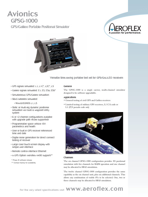
Aeroflex GPSG-1000 多频道 GPS Galileo 移动测试设备说明书
ChannelsSimulationThe Simulation page shows the selected GNSS signals generated and provides a PVT (Position, Velocity and Time) display. The data displayed also includes the current waypoint leg, heading and distance to go.In the Static mode of operation, a 3D position may be user entered in Latitude/Longitude/Height format. Almanac data is derived either from the built-in L1 C/A Code GPS receiver or via an external file load. Positional simulation may also be synchronized to UTC via the receiver.SV SelectionAll GPSG-1000 configurations allow GPS and Galileo satellites to be mixed. SVs are allocated automatically for optimal geometry accord-ing to simulated position. The user may turn off individual SVs, to create scenarios with poor geometry for RAIM testing.Each SV may have Doppler, Amplitude, Step Error and Code Carrier Coherence parameters deviated from nominal and Satellite Health set.Signal Fading and Dynamic Signal Amplitude and Simulator RF level may be applied to all satellites.SBASSBAS satellites WAAS/EGNOS are automatically allocated based on simulated position. The user can select the number of SBAS SVs that can be allocated and can selectively turn off individual SVs.WaypointsWaypoints may be created and stored in Latitude/Longitude/ Altitude form or automatically recalled from the provided waypoint data base organized by an airport or city. Waypoints may be selected for inclusion in a route in dynamic mode or as a single position in static mode.RoutesIn the Dynamic position mode of operation, the Route page may be used to sequentially enter user defined route points. Routes compris-ing of up to 99 route points, may be saved and recalled under a user entered route name, using the route file management system. Route points can be reordered, edited or deleted. 3D position data compris-ing Latitude, Longitude and Altitude may be manually entered, or selected from the waypoints page. Additional parameters that define a route point are.. Speed, Linear Acceleration and Altitude Rate.T urns may be executed at the route point, utilizing a user defined T urn Radius. Realistic turns are maintained to 10G.SetupThe Setup page is partitioned via a tab selection scheme to allow control for Simulation, Almanac, Channels and I/O.The simulation tab provides controls for GNSS System Selection and Carrier, also Digital Noise, Multipath (fading) model selection, PRN RF Signal levels, Position Source, Simulation T ype and SBAS.FileThe file management system is partitioned via a tab selection scheme. File management is provided for almanacs, routes and simulator settings. Facilities include loading, storage, and naming of files.** Contact factory for availability A-GPS (Assisted GPS) – Option**The A-GPS option allows the GPSG-1000 to be used in conjunction with the Aeroflex 4400 CDMA Mobile Phone T ester, to provide a comprehensive test of the mobile phone built-in GPS receiver using the A-GPS protocols.The GPSG-1000 provides a predefined scenario 62.5 min, or 5 navi-gation messages in length. Three data files are created after an initial real-time run of the simulation, which are provided over the Ethernet interface via a set of remote commands. The files are:Acquisition: Time stamped dataProcessed Navigation Data: Time stamped almanac and ephemeris data in engineering unitsRaw Navigation Data: (5 messages) used for sensitivity assistanceThe GPSG-1000 can store the scenarios and the relevant files generated in simulator memory using the settings storage facility provided in the GPSG-1000 GUI.The 4400 utilizes the three file types, which are in a time stamped format, for creating assistance data that is sent to the phone under test upon request. The 4400, via the Ethernet interface, can arm the GPSG-1000 simulation and provide a hardware trigger of the simulation. The GPSG-1000 external 10 MHz clock is provided by the 4400, allowing the synchronization of the RF simulation with the data used in the simulation, stored in the 4400 memory.For more information about the Aeroflex 4400, please use the following link:/ats/products/product/Communications_Test/Cellular_Parametric_Test/4400_Mobile_Phone_Tester_Series~756.html#For the very latest specifications visit L1 (P)Y (not encrypted)Code Rate10.230 Mc/sSequence Length15345000 bitsModulationBPSKNote: Long random codes simulatedL1C*Code Rate10.230 Mc/sSequence Length10230 bitsModulationBOC (1, 1)L5Code Rate10.230 Mc/sSequence Length10230 bitsModulationQPSKGALILEO SERVICESE1Pseudo G/NAVLong random codes simulatedCode Rate2.5575 Mc/sSequence LengthTBCSymbol RateTBCModulationInterplex/CBOCSub ModulationBOC (15,2.5)Note: PRS not supportedE1OSComplete implementation (I/NAV)* Phase III software releaseCSNull message content (pseudo I/NAV)SoLCompliant, no integrity alerts (I/NAV)Code Rate1.023 Mc/sSequence Length4092 (primary) x 1 (secondary) bitsSymbol Rate250 spsModulationInterplex/CBOCSub ModulationCBOC(6,1,1)E5aOSComplete implementation (F/NAV)Code Rate10.23 Mc/sSequence Length10230 (primary) x 20 (secondary) bits Symbol Rate50 spsModulationALTBOCSub ModulationNoneE5b*OSComplete implementation (F/NAV)CSNull message content (pseudo I/NAV)SoLCompliant, no integrity alerts (I/NAV)Code Rate10.23 Mc/sSequence Length10230 (primary) x 4 (secondary) bitsSymbol Rate250 spsModulationALTBOCSub ModulationNoneFor the very latest specifications visit Safety ComplianceUL-61010:2001CSA 22.2 No 1010.1WEEEROHSEMCEmissionsMIL-PRF28800F Class 2EN 61326:1998 Class AEN 61000-3-2EN 61000-3-3ImmunityMIL-PRF28800F Class 2EN 61326:1998 Class AExternal AC-DC Converter CertificationsSafety ComplianceUL 1950 DSCSA 22.2 No. 234VDE EN 60 950EMI/RFI Compliance FCC Docket 20780 Curve "B"EMC EN 61326Transit Case CertificationsDrop Test FED-STD-101C Method 5007.1Paragraph 6.3, Procedure A, Level AFalling Dart Impact ATA 300 Category IVibration, Loose Cargo FED-STD-101C Method 5019Vibration, Sweep ATA 300 Category ISimulated Rainfall MIL-STD-810F Method 506.4 Procedure II of 4.1.2 FED-STD-101C Method 5009.1 Sec 6.7.1Immersion MIL-STD-810F Method 512.4 ENVIRONMENTAL (SUPPLIED EXTERNAL AC TO DC CONVERTER)UseIndoorsAltitude≤10,000 feetOperating Temperature5°C to 40°CStorage Temperature-20°C to 71°CPHYSICAL CHARACTERISTICSGPSG-1000Height10.63 in. (27.0 cm)Width13.97 in. (35.5 cm)Depth3.425 in. (8.7 cm)Weight (Test set only)<10 lbs. (4.5 kg)ANTENNA COUPLERHeight7.54 in. (191.5 cm)Width7.46 in. (189.5 cm)Depth7.46 in. (189.5 cm)(Note: Maximum antenna height accommodated 1.5 in) RF GasketFlexible sealConnectorTNCPositioningBy hand or with optional 8ft placement pole via hook.Placement SecurityWeighted peripheral bagFor the very latest specifications visit VERSIONS, OPTIONS AND ACCESSORIESOrdering DescriptionNumber87339GPSG-1000 6 Satellite Simulator87715GPSG-1000 12 Satellite Option89475GPSG-1000 A-GPSG Option**Standard Accessories88493T ransit case (qty 1)67374Power supply87636Antenna coupler90113RX Antenna90114Cable, coax 50 ft.62302Power cord (U.S)64020Power cord (European)88037Operation Manual (CD)88038Getting Started Manual (paper)Optional Accessories87040External battery charger86196Spare battery pack90106Kit, Antenna coupler placement pole 8 ft.89023Maintenance Manual (CD)**** Contact factory for availability。
GSS8000模拟器参数测试报告
GSS8000模拟器性能参数测试报告本振精度和输出射频信号的幅度精度是决定GSS8000高精度GNSS信号模拟器输出信号品质的关键性指标,本报告的内容即给出了测试这些指标的参考方法和参考评定标准。
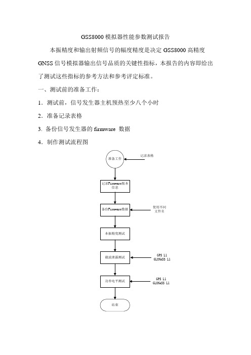
一、测试前的准备工作:1.测试前,信号发生器主机预热至少八个小时2.准备记录表格3. 备份信号发生器的firmware 数据4.制作测试流程图使用不同文件名GPS L1GLONASS L1GPS L1GLONASS L1二、本振精度的参考测试方法:1.将频率计数器连接到后面板的“INT REF OUT”端口,频率计数器需要与高精度频标同步。
2.确定信号发生器的“Ext Ref In”端口悬空3.记录频率计数器读数并计算频率偏差。
测得频率应当在10.23MHz 标称频率的±1Hz以内。
4.使用随机工具箱中的改锥通过信号发生器前面板内部的调节孔找到本振调节螺钉。
5.调整调节螺钉使频率计数器读数在10.23MHz的±0.02Hz以内。
6.记录频率计数器读数,计算误差并确认在允许范围内。
三、载波泄露测试方法:1.信号发生器面板移除1)操作人员立于信号发生器后侧,使用合适的工具松动设备上面板紧固螺钉。
2)小心移除上面板,不要拉断接地线缆。
将上面板置于安全处。
3)翻转信号发生器机箱,注意不要扯断机箱内线缆。
4)操作人员立于信号发生器后侧,使用合适的工具松动设备下面板紧固螺钉。
5)小心移除下面板,不要拉断接地线缆。
将下面板置于安全处。
6)将信号发生器顺时针旋转90度,处于如下图所示状态。
2.确定调节螺钉位置按照下表所示位置确定调节螺钉的位置:如下图所示确定不同载波的接口位置:测试其中一路信号的载波泄露时,需要将另外一路的接口断开;测试结束后,将断开的接口回复。
3.GPS信号测试1)将频谱分析仪连接到对应的Mon/Cal Out端口。
2)使用指令CONF2 SDC!复位信号发生器。
3)使用指令CPUS1 CHAN0 CAL1 COSW0 RUN: 产生载波信号。
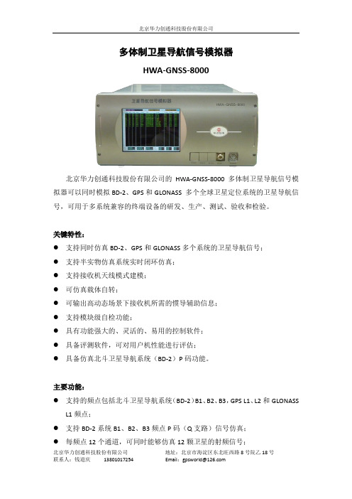
HWA-GNSS-8000 多体制卫星导航信号模拟器
运输要求:
满足三级公路运输要求
可靠性
平均故障间隔时间(MTBF): ≥3000 小时
平均故障修复时间(MTTR): ≤2 小时
一次连续工作时间:
≥24 小时
计算机工作站推荐配置
操作系统:
Windows XP 或以上
处理器:
intel @2GHz 或更高
对外接口:
RS232 或 千兆以太网口
北京华力创通科技股份有限公司
可选配置 (一) 实时闭环
在 HWA-GNSS-8000 卫星导航信号模拟器的基础上增加实时闭环功能,实时 接收载体运动轨迹,实时生成卫星导航数据,满足多信号体制下的实时半实 物仿真系统闭环仿真测试需求。 (二) 惯导辅助 在 HWA-GNSS-8000 卫星导航信号模拟器的基础上增加惯导辅助,与卫星导 航信号同步输出三维位置、三维速度、三维加速度,辅助接收机在高动态下 捕获、跟踪和定位。 (三) 多径信号 在 HWA-GNSS-8000 卫星导航信号模拟器的基础上每个频点能够增加 6~12 个多路径信号与主径信号合成输出。 (四) 载体自转仿真 HWA-GNSS-8000 的控制仿真软件可以支持模拟在载体自转时,卫星导航信号 的变化情况。从而使卫星导航接收设备在地面测试中,充分模拟真实的运动 情况。
13801017254
地址:北京市海淀区东北旺西路 8 号院乙 18 号 Email:gpsworld@
北京华力创通科技股份有限公司
配置数据仿真软件,能够根据用户要求对仿真数据进行配置,如卫星轨道数 据,电离层、对流层参数、用户轨迹等;
控制软件可对卫星导航信号模拟器输出进行信号中断、信号恢复、开关每一 个可见星信号、调制方式选择和功率控制等;
-90dBc/Hz@1kHz
徕卡GS GS 连接VRS CORS 流动站设置操作说明
流动站设置- 新建RTK向导
SIM卡的PIN&PUK码,一般不用输入。 选择使用GPRS/CDMA连接因特网。
网络RTK设置与观测
内业设置
流动站设置- 新建RTK向导
输入APN 因河北省CORS是专网专卡,所以输 入一长串比较奇怪的字符
有时手簿顶部手机图标上有个黄色的 叹号,就是因为还没有联网,把这个 APN输入后一般可以解决。
流动站设置- 卫星跟踪设置
在 高级 页面,根据需要设置截 止角、DOP限值、L2C跟踪和卫 星健康状况。设置完毕后,点击 确定,卫星跟踪设置完成,退到 主菜单。
传统RTK设置与观测
内业设置
流动站设置- 天线类型设置
主菜单选择仪器。
GPS设置。
传统RTK设置与观测
内业设置
流动站设置- 天线类型设置
天线高。
设置流动站天线、测点时天线高和移动时 的天线高。
传统RTK设置与观测
内业设置
流动站设置- 新建RTK向导-电台通讯
开机,主菜单选择仪器
选择GPS设置
传统RTK设置与观测
内业设置
流动站设置- 新建RTK向导-电台通讯
GPS设置界面,选择RTK流动站向导。 选择创建一个新模式。
传统RTK设置与观测
徕卡GPS GS14、GS15 RTK使用说明
传统RTK设置与观测
内业设置
流动站设置- 卫星跟踪设置
主菜单选择仪器。
GPS设置。
传统RTK设置与观测
内业设置
流动站设置- 卫星跟踪设置
卫星跟踪。
在 跟踪 页面双星用户可以根据自己的需要 选择卫星信号,设置完毕后点击 换页。
传统RTK设置与观测
内业设置
卫星信号模拟器
• 段相重疊。B2、B3 頻段信號的定義尚未正式公佈,因此本應用說明僅描
• 述 B1I 信號。
北斗(BDS)
• • • • • • • • • 北斗發射信號 和 GPS 和 Galileo 一樣,北斗系統也是不同衛星使用不同測距碼的 CDMA 系統。MEO 和 IGSO 衛星所傳輸的信號與 GEO 衛星傳輸的信號不同。 北斗信號成分 北斗 E1 信號包含以下組成部分,如圖 11 所示: – 測距碼 – 二次( Neumann-Hoffman)編碼 – 導航電文 – 載波
Galileo 和北斗這兩個系統目前仍處於部署進程中。Galileo 系統是多年前由歐盟和歐洲航太總署共 同開發的。2005 年和 2008 年共發射了兩顆實驗衛星,2011 和 2012 年,發射了 4 顆在軌驗證衛星。 Galileo 系統計畫於2015 年提供初始服務,整個系統預計於 2020 年部署完成。
透過三邊量測法
GNSS 衛星信號的傳輸功率很低。在地球表面,其功率位準大約 為 -155 至 -160 dBW( -125 至 -130 dBm)。如果有遮蔽物,則信號功 率會更低。 GNSS 接收器內含放大器和信號處理器,可恢複 GNSS 信號。
圖 2:透過三邊量測法,GNSS 接收器可計算與至少三顆衛星 的距離。使用衛星 虛擬距離球面的交叉點,您可確定接收器的位置。
是将卫星信号放大后转发至室内,这种方法的坏处是噪声和和信号都同时放大,当达到
抗干扰天线时信号也会被抗干扰天线抵消,造成搜星信噪比低,或者无法搜星。使用转 发式模拟器的好处是转发器发出的是纯的卫星导航信号,不存在噪声,到达抗干扰天线 面时不会被抵消,可以有效解决抗干扰天线在实验室、暗室、厂房的测试。
接收器軟體顯示用導航電文 – 明德碼( Meander code)
GNSS-5000A高动态GPS卫星信号模拟器用户手册(白色单模)
GNSS-5000A多通道GPS模拟器用户手册深圳市中冀联合通讯技术有限公司目录1GNSS-5000A模拟器简介 (1)1.1GNSS-5000A模拟器 (1)1.2GNSS-5000A模拟器外观 (1)2主要指标及测试图 (2)2.1主要特点 (2)2.2性能指标 (2)2.3定位测试结果图 (4)3模拟器操作过程 (4)3.1硬件设置 (4)3.2软件操作 (4)3.3运行场景 (9)3.4模拟器状态查看 (11)3.4.1Satellite Data (11)3.4.2星空图 (11)3.4.3NMEA数据 (12)3.4.4位置信息 (12)3.4.5模拟位置实时显示 (12)3.4.6界面总体图 (13)3.5模拟器功率设置 (13)4场景设置 (15)4.1场景的定义 (15)4.2星历和时间 (15)4.3轨迹模型 (16)4.4轨迹设置 (16)4.5场景实例 (17)4.5.1静态场景 (17)4.5.2动态场景 (18)1GNSS-5000A模拟器简介1.1GNSS-5000A模拟器GNSS-5000A是一款具备多种功能的简易型便携式GPS模拟器,是为方便用户的测试需求而设计的。
该型号模拟器提供了灵活的上位机软件界面方便用户设置各种测试场景(轨迹,此为扩展功能),一键自动保存上位机设置的场景(轨迹场景)、脱离上位机运行保存的测试场景(轨迹场景),极大方便用户在产线、野外等环境下的测试。
该模拟器在测试、评估及检验接收机定位精度等性能时可代替费用昂贵的模拟器进行现场实验,实时性好、性价比高,方便GPS领域的研发和生产测试等各个环节。
1.2GNSS-5000A模拟器外观2主要指标及测试图2.1主要特点与国内外现有GPS卫星信号模拟器相比,GNSS-5000A卫星信号模拟器具有以下几个特点:⏹实时信号输出开机即输出实时射频GPS信号;利用预存场景时,无需设置;⏹无限时信号连续输出星历可自动更新;无限时连续信号输出,支持接收机24/72小时/无限时连续信号测试;⏹用户场景参数设置方便用户运动状态可设:包括位置、速度、加速度;可使用用户定义场景文件;⏹卫星信号状况可视可调实时显示模拟多通道卫星信息及星空图;卫星信号功率可调;⏹操作方便控制界面一体化设计;2.2性能指标⏹信号规模GPS的L1频点,最多12通道⏹信号动态参数最大速度0~50000m/s最大加速度0~1000m/s2最大加加速度0~1000m/s3⏹信号精度伪距相位控制精度优于0.02m伪距变化率精度优于0.005m/s通道间一致性0.5ns⏹信号质量频率稳定度±1x10-8相位噪声-80dBc/Hz100Hz;-85dBc/Hz1kHz;-90dBc/Hz10kHz;-95dBc/Hz100kHz;谐波功率(MAX)-40dBc杂波功率(MAX)-50dBc⏹信号功率电平控制功率范围:-100dBm至-163dBm 功率精度:±1dB⏹参考频率/定制时钟输出10MHz时钟输入10MHz⏹电气和物理特性电源220V机箱优质钢板成型,喷涂高温烘漆保护,高强度铝合金面板重量10kg尺寸480mm(长)×367mm(宽)×110mm(高)2.3定位测试结果图附一组静态测试结果,仅供参考。
GPS中频信号模拟器的数学模型及实现
ISSN 100020054CN 1122223 N 清华大学学报(自然科学版)J T singhua U niv (Sci &Tech ),2008年第48卷第10期2008,V o l .48,N o .10w 12h ttp : qhxbw .ch inaj ournal.net .cn GPS 中频信号模拟器的数学模型及实现李成军1,2, 陆明泉1, 冯振明1(1.清华大学电子工程系,北京100084;2.中国人民解放军91635部队,北京102249)收稿日期:2007207218作者简介:李成军(1976—),男(汉),江苏,博士研究生。
通讯联系人:冯振明,教授,E 2m ail :fz m @tsinghua .edu .cn摘 要:为了给全球定位系统(GPS )软、硬件接收机提供高保真的测试环境,在分析GPS 信号传输路径各种影响的基础上,推导了GPS 中频信号模拟器的数学模型,提出利用已有星历计算卫星传输时间和仿真误差源的方法,并给出了软件的实现方案。
利用软件GPS 接收机测试仿真信号结果表明:利用该方法能够正确地模拟中频GPS C A (粗码)和P(精确码)卫星信号。
该方法实现简单,通过增加相应的算法能够模拟各种类型的GPS 信号,可以对软、硬件接收机的捕获、跟踪以及测量精度进行测量鉴定,为新技术的应用提供开发环境。
关键词:GPS (全球定位系统)信号模拟器;GPS 接收机;捕获;跟踪;定位解算中图分类号:TN 965.5文献标识码:A文章编号:100020054(2008)1021578204M a thema tica l m odel and rea liza tion forGPS IF signa l si m ula torL I Che ng jun 1,2,LU M ingqua n 1,FE NG Zhengm ing 1(1.D epart men t of Electron ic Eng i neer i ng ,Tsi nghua Un iversity ,Be ij i ng 100084,Ch i na ;2.Un it 91635of PLA ,Be ij i ng 102249,Chi na )Abstract :Global po siti oning system (GPS )IF signal si m ulato rs p rovide high 2fidelity m easurem ent environm ents fo r GPS softw are o r hardw are receivers .Based on analyzing the effects of erro r sources on GPS signals,the m athem atical models of IF si m ulato r and algo rithem s of computing trans m issi on ti m e by using existing ephem eris are p resent .A softw are realizati on of a GPS IF signal si m ulato r is p resented w here the si m ulated signal is p rocessed by a softw are GPS receiver .M easurem ent results show that this m ethod accurately si m ulates GPS IF C A and P codes .T h is schem e can be easily realized and expanded to si m ulate o ther GPS signals by adding o ther algo rithm s fo r evaluating acquisiti on,tracking and p recisi on of GPS softw are o r hardw are receivers .T his m ethod also suppo rts new GPS techno logy developm ent .Key words :GPS (global po siti oning system )signal si m ulato r;GPSreceiver;acquisiti on;tracking;Po siti on fix全球定位系统(GPS )信号模拟器可以根据载体的运动状态精确模拟载体所接收的GPS 的卫星信号,用于对接收机的捕获、跟踪以及定位解算精度进行测量,为GPS 接收机的开发以及新技术的运用提供开发环境。
GSG-5 6 卫星导航信号模拟器产品介绍说明书
Basic PrincipleG SG -5/6 simulators can generate any combination of G PS, G LONASS, G alileo, BeiDou, QZSS, SBAS satellite signals un-der any condition simultaneously through a single RF out-put (type N connector). Configurations with higher channel counts generate new, modernized, signals on any of the navi-gation frequencies, including IRNSS, even those currently un-der development. Based on a test scenario that includes date, time and power levels, the generated signals correspond to any position on, or above, the earth (below the satellite orbits at approximately 20,000 km). It is easy to test dynamic condi-tions by defining a trajectory of the receiver under test. The simulator manages all the dynamics including relativistic effects.Test Solutions•Position/navigation accuracy •Dynamic range/sensitivity•Simulate movements/trajectories anyway on or above earth •Susceptibility to noise•Sensitivity to GPS impairments: loss of satellites, multi-path, atmospheric conditions, interference, jamming and spoofing •Conducted or over-the-air RF •GPS time transfer accuracy •Effect of leap second transition •Multiple constellation testing•Modernization signals/ frequencies •Hardware in the loop integrationGSG-5/6 SeriesAdvanced GNSS Simulators•Pre-defined or user-defined test scenarios•Full control over all test parameters•Front panel interface/stand-alone operation•Windows-based scenario builder software including Google Maps •Remote operation by Ethernet, GPIB, USB •Built-in or downloadable navigation files•Full control over trajectories and other dynamics •Up to 64 simultaneous signals•All GNSS constellations and frequencies•Accurate, adjustable power levels•Synchronization features to external devices or other simulatorsSimulation is simply the best way to test and verify proper operation of devices, systems and software reliant on global navigation satellite signals.Pendulum G SG -5/6 series simulators are easy-to-use, feature-rich and affordable to offer the best value compared to alternative testing tools or the limitations of testing from “live sky” signals. | *****************************•Constellations: GPS, GLONASS, Galileo, BeiDou, QZSS, IRNSS •Modulations: BPSK, QPSK, BOC (all)•SBAS: WAAS, EGNOS, GAGAN, MSAS, SAIF (included)•Spurious transmission: ≤40 dBc •Harmonics: ≤40 dBc•Output signal level: -65 to -160 dBm; 0.1 dB resolution down to -150 dBm; 0.3 dB down to -160 dBm•Power accuracy: ±1.0 dB •Pseudorange accuracy: Within any one frequency band:1 mm; Across different frequency bands: 30 cm•Inter-channel bias: Zero•Inter-channel range: >54 dB •Limits:Standard ExtendedAltitude18,240 m(60,000 feet)20,200,000 m (66,273,000 feet)Acceleration 4.0 g No limitsVelocity515 m/s (1000knots)20,000 m/s (38,874 knots)Jerk20 m/s3No limit •White noise signal level: -50 to -160 dBm; 0.1 dB resolution down to -150 dBm;0.3 dB down to -160 dBm. ±1.0 dB accuracy External Frequency Reference Input •Connector: BNC female•Frequency: 10 MHz nominal•Input signal level: 0.1 to 5Vrms•Input impedance: >1kΩFrequency Reference Output •Connector: BNC female•Frequency: 10 MHz sine•Output signal level: 1Vrms in to 50 Ω load External Trigger Input•Connector: BNC female•Level: TTL level, 1.4V nominalXPPS Output•Connector: BNC female•Rate: 1, 10, 100, 1000 PPS (configurable)•Pulse ratio: 1/10 (1 high, 9 low)•Output signal level: approx. 0V to +2.0V in 50 Ω load•Accuracy: Calibrated to ±10 nSec of RF timing mark output (option to reduce by a factor of ten with a characterization of offsets)Built-in TimebaseInternal Timebase – High Stability OCXO •Ageing per 24 h: <5x10⁻¹⁰•Ageing per year: <5x10⁻⁸•Temp. variation 0…50°C: <5x10⁻⁹•Short term stability (Adev @1s): <5x10-12 Auxiliary FunctionsInterface•GPIB (IEEE-488.2), USB 1.X or 2.X (SBTMC-488), Ethernet (100/10 Mbps)Settings•Predefined scenarios: User can change date, time, position, trajectory, number of satellites, satellite power level and atmospheric model •User defined scenarios: Unlimited •Trajectory data: NMEA format (GGA or RMC messages, or both), convert from other formats with GSG StudioView™ (see separate datasheet)General SpecificationsCertifications•Safety: Designed and tested for Measurement Category I, Pollution Degree 2, in accordance with EN/IEC 61010-1:2001 and CAN/CSA-C22.2 No. 61010-1-04 (incl. approval)•EMC: EN 61326-1:2006, increased test levels per EN 61000-6-3:2001 and EN 61000-6-2:2005 Dimensions•WxHxD: 210 x 90 x 395 mm(8.25” x 3.6” x 15.6”)•Weight: approx. 2.7 kg (approx. 5.8 lb) Optional Antenna•Frequency: 1000 to 2600 MHz •Impedance: 50 Ω•VSWR: <2:1 (typ)•Connector: SMA male•Dimensions: 15 mm diameter x 36 mm length Environmental•Class: MIL-PRF-28800F, Class 3•T emperature: 0°C to +50°C (operating); -40°C to +70°C non-condensing @ <12,000 m (storage)Humidity:•5-95 % @ 10 to 30°C•5-75 % @ 30 to 40°C•5-45 % @ 40 to 50°CPower•Line Voltage: 100-240 V AC, 50/60/400 Hz •Power Consumption: 40 W max.Simple Set-up and Operation Even the most inexperienced operator can configure scenarios on-the-fly without the need for an external PC and pre-compila-tion phase. Via the front panel, the user can swiftly modify parameters. Each unit comes with a license for GSG StudioView™ Windows software to graphically create, modify, and upload scenarios. A G oogle Maps interface makes trajectory creation easy. Trajectories can also be defined by recorded or generated NMEA formats. Connectivity Extends Ease-of-use and FlexibilityG SG simulators can be controlled via an Ethernet network connection, USB or GPIB. A built-in web interface allows complete operation of the instrument through front panel controls. It also al-lows for file transfers. Connectivity also supports the integration of G NSS simula-tion into a wide range of other applica-tions. There is an option to control signal generation in real-time through a simple command set. It can synchronize to ex-ternal systems in many other ways based on its precision timing capabilities and the ability to automatically download ephem-eris and almanac data via RINEX files. Input/OutputRF GNSS Signal Generation •Connector: Type N female•DC blocking: internal, up to 7 VDC; 470 Ωnominal load•Frequency bands:•L1/E1/B1/SAR: 1539 to 1627 MHz•L2/L2C: 1192 to 1280 MHz•L5/E5/B2: 1148 to 1236 MHz•E6/B3:1224 to 1312 MHz•Output channels:•1 (GSG-51); 4, 8, 16 (GSG-5); 32 (GSG-62),48, (GSG-63), 64 (GSG-64)•Any channel can generate anyconstellation or a derivative signal(multipath, interference, jamming)•Any set of 16 channels can generate withina frequency bandOptional FeaturesRecord and Playback (OPT-RP)This option provides the easiest way to create a complex scenario by recording satellite signals on a route. This option includes a recording receiver and software to automatically generate a simulation scenario that can be modified to ask ‘what if’ questions.•True life constellation replication •Automatic scenario generation•Ability to modify signal parameters •Compatible with any recording that includes NMEA 0183 RMC, GGA, and GSV sentences Real-time Scenario Generator (OPT-RSG) This option supports generation of 6DOF trajectory information via position, velocity, acceleration, or heading commands as the input for GPS RF generation. Vehicle attitude and attitude rate changes, as well as satellite power levels, are also controllable via real-time commands.•Control trajectories using 6DOF•Low fixed latency from command input to RF output•Hardware-in-the-loop applications •Includes sensor simulation optionRTK/DGNSS Virtual Reference Station (OPT-RTK)This option supports generation of RTCM correction data messages for testing an RTK / Differential-GNSS receiver.•Generates RTCM 3.x correction data via 1002, 1004, 1006, 1010, 1012, and 1033 messages•User settable base station location •Support for GNSS RTK receivers using serial interfacesHigh Velocity Option (OPT-HV)This option extends the limits for simulated trajectories. As of August 2014, the extended limits are no longer USA export controlled. (See Limits chart under Input/Output specifications.) Jamming Simulation (OPT-JAM)This option extends the capability of the standard interference simulation feature. Set noise or sweep types of interference and create a location-based jammer to test your system’s susceptibility.•Adjustable bandwidth and amplitude interference•Location-based jamming•Swept-frequency jammingeCall Scenarios (OPT-ECL)This option provides scenarios for testing eCall in vehicle systems per Regulation (EU) 2017/79.Sensor Simulation (OPT-SEN)This option generates sensor data in responseto a query according to the trajectory of theGPS RF simulation in real-time. See technicalnote for more details.•Simultaneously test GPS plus other sensorinputs to your nav system•Simulate data for accelerometers,gravimeters, gyroscopes and odometersOrdering InformationBase Configurations•GSG-51: Single channel GPS L1 generator(contact the factory for alternativeconstellations and upgrades to multi-channeland/or frequencies)•GSG-5: 4-channel GPS L1 simulator.Software options increase output channelsto 8 or 16, and adds GLONASS, BeiDou (B1),Galileo (E1), or QZSS constellations. Factoryupgradable to GSG-62 to add more channeland/or frequencies)•GSG-62: 32-channels and up to 2simultaneous frequency bands. Softwareoptions adds GLONASS, BeiDou, Galileo,QZSS or IRNSS constellations; and addssignals on other frequencies (P-code, L2,L2C, Galileo E5a/b, BeiDou B2)•GSG-63: 48-channels and up to 3simultaneous frequency bands. Samesoftware options as GSG-62•GSG-64: 64-channels and up to 4simultaneous frequency bands. Samesoftware options as GSG-62Included with instrument•User manual and GSG StudioView software(one license per unit) on CD•RF cable, 1.5 m•SMA to Type N adapter•USB cable•Certificate of calibration•3-year warranty1Optional Accessories•Option 01/71: Passive GNSS Antenna•Option 22/90: Rack-mount kit•Option 27H: Heavy-duty hard transport case•OM-54: User Manual (printed)•Additional StudioView licenses are availableOptional UpgradesConstellations•OPT-GLO: GLONASS Constellation•OPT-GAL: Galileo Constellation•OPT-BDS: BeiDou Constellation•OPT-QZ: QZSS Constellation•OPT-IRN: IRNSS Constellation (requires atleast GSG-62 and OPT-L5)Frequencies (requires at least GSG-62; non-GPS signals are enabled when constellationoption is installed)•Option L2: enables GPS L1P, GPS L2P, GLOL2 C/A•Option L2C: enables GPS L2C•Option L5: enables GPS L5, Galileo E5 a/b,BeiDou B2, IRNSS L5•Option L6: enables Galileo E6 b/cChannels/Simultaneous Frequencies2•Option 8: 4-channel to 8-channel upgrade•Option 16: 8-channel to 16-channel upgrade•Option 32/2: 16-channel to 32-channel, dualfrequency upgrade•Option 48/3: 32-channel to 48-channel, threefrequency upgrade•Option 64/4: 48-channel to 64-channel, fourfrequency upgradeApplication Packages (typical requirement for16 channel min)•OPT-RSG: Real-time scenario generator•OPT-HV: High velocity upgrade to extendedlimits•OPT-RP: Record and playback package•OPT-JAM: Jamming package•OPT-RTK: RTK virtual base station scenarios•OPT-SEN: Sensor simulation data via protocol(included with OPT RSG)•OPT-ECL: eCall scenariosOptional Services•Option 90/54:GSG Calibration Service•Option 95/05: Extended warranty to 5 years•GSG-INST: User Training and Installation•OPT-TIM: Timing Calibration Service1Warranty period and available services may vary dependent on country.2Option may require the unit to be returned to factory for upgrade.Models Channels # of Sim.Freq.Upgrade to nexthigher modelUpgradetypeConstellations and Signal T ypes Frequency BandsGSG-5111OPT-4Software GPS L1 C/A IncludedOthers if constellation is ordered:•GLONASS L1 C/A •QZSS L1•Galileo E1•BeiDou B11539-1627 MHz (L1)GSG-541OPT-8Software 8OPT-16Software 16OPT-32/2FactoryGSG-62322OPT-48/3Factory Same as aboveOptions if constellation andfrequency are ordered:•GPS L1P, L2P, GLONASS L2 C/A (OPT L2)•GPS L2C (OPT L2C)•GPS L5, IRNSS L5, Galileo E5a/b,BeiDou B2 (OPT L5)Same as above and 3 other ranges•1192-1280 MHz (L2)•1148-1236 MHz (L5)•1224-1312 MHz (E6/B3)GSG-63483OPT 64/4FactoryGSG-64644––Configuration SummaryOct 29, 2018 rev.2© 2018, Pendulum Instruments and OroliaSpecifications subject to change or improvement without notice.。
gnss卫星信号模拟器的介绍
gnss卫星信号模拟器的介绍gnss信号模拟器,卫星信号模拟器,gnss卫星信号模拟器卫星信号模拟器是一种精确度非常高的信号发射装置,发射出来的信号能够被一些特殊的卫星所接收作为导航信息使用,为导航接收装置的开发研究、数据测试创造了良好的条件,是导航接收装置在设计与开发过程必不可少的部分。
根据卫星导航信号模拟器可模拟的卫星通道数量的不同,可以将模拟器分为单通道模拟器和多通道模拟器两种类型。
GPS卫星信号模拟器根据GPS信号发射装置、计算机和信号接收装置共同组成,GPS 信号发生装置由多种不同的硬件组成,这种信号发生装置能够在同一时间产生多种多样的通道的信号。
信号接收装置是GPS信号发生器核心组成部分,GPS信号发生装置所用到的各种信号都是从仿真软件计中整理得出的。
gnss卫星信号模拟器主要可以分为以下2种:基于软件的模式:在这种运营模式下,所有和导航相关的信息和信号都是通过计算机处理获得,包括对各种模型的数据和信号都是通过计算机软件进行计算处理后,存储在相关设备中进行保存。
基于软硬件结合的模式:在这种运营模式下,计算机软件主要负责整理和计算相关的信息与信号,然后运用与信号相一致的参数控制硬件对整理的信息进行分析,发射出卫星信号。
厂家直销:刘经理189********SYN5203型GPS信号模拟器是由西安同步电子科技有限公司精心设计开发生产的一款低成本卫星导航gnss卫星信号模拟器,模拟GPS卫星导航定位系统的导航信号,支持GPS L1频点的射频仿真信号输出,支持实时星历和外部星历参数输入,支持不同时间长度的各种轨迹输出,能满足各类GPS导航授时接收终端的测试需求,可替代国外高昂GPS模拟器。
在使用当中SYN5203型有标准2U机箱式的还有小模块的方便不同用户,不同场景下的使用。
可实时GPS、北斗信号模拟,灵活生成和编辑场景文件用于静止和移动接收机测试。
小型模拟器设有USB接口,通过USB接口与电脑通信,通过电脑上位机软件快速设置各种参数及制作轨迹。
中冀联合GPS北斗GLONASS卫星信号模拟器(三模)
GNSS多通道卫星模拟器用户手册深圳市中冀联合通讯技术有限公司目录1 GNSS多通道卫星模拟器简介 (1)1.1 GNSS多通道卫星模拟器 (1)1.2 GNSS多通道卫星模拟器外观 (1)2 主要指标及测试图 (2)2.1 主要特点 (2)2.2 性能指标 (2)2.3 定位测试结果图............................................................................. 错误!未定义书签。
3 模拟器操作过程 (4)3.1 硬件设置 (4)3.2 软件操作 (4)3.3 运行场景 (9)3.4 模拟器状态查看 (10)3.4.1 Satellite Data................................................................. 错误!未定义书签。
3.4.2星空图.................................................................................. 错误!未定义书签。
3.4.3 NMEA数据............................................................................ 错误!未定义书签。
3.4.4位置信息.............................................................................. 错误!未定义书签。
3.4.5 模拟位置实时显示............................................................. 错误!未定义书签。
3.4.6 界面总体图......................................................................... 错误!未定义书签。
- 1、下载文档前请自行甄别文档内容的完整性,平台不提供额外的编辑、内容补充、找答案等附加服务。
- 2、"仅部分预览"的文档,不可在线预览部分如存在完整性等问题,可反馈申请退款(可完整预览的文档不适用该条件!)。
- 3、如文档侵犯您的权益,请联系客服反馈,我们会尽快为您处理(人工客服工作时间:9:00-18:30)。
允许载体动态范围: 速度: 速度分辨率: 加速度: 加速度分辨率: 加加速度: 加加速度分辨率:
用户界面: 模拟场景:
弯运动等 编程参数:
速度,向心加速度等 报文编辑功能:
信号产生单元: 尺寸: 重量: 电源: 工作温度:
0~16000m/s
10mm/s
0~900m/ s2 P
10mm/ s2 P
系统组成: 序号
规格名称
GSS900
1
GPS 信号模拟器
2
以太网电缆
3
射频转接套件
4
电源线
GSS900
5
技术参考手册
6
GSS900 使用说明书
7
GSS900 软件光盘
8
GSS900 安装手册
9
GSS900 质保单
10
GSS900 合格证
11
GSS900 装箱单
单位
台
根 套 根
册
册 张 册 份 份 份
-60dBm 至-160dBm(12 个通道每个通道都可以单独调节) ±(0.25dB+衰减调节设置值的 4%) 1dB±0.5dB 1.5:1(最大)
16.384MHz±5Hz OCXO <±0.01ppm(-30℃~+70℃) <-30dBc
优于 0.001m 优于 0.003m/s ±0.01 米 0.3ns <1 度 <1 度 <0.2ns(1 天
z 测距码精度达到±0.001 米(RMS);
z 可测速度范围 0~16000m/s;
z 可测加速度 0~900m/ s2;
P
P
z 加加速度 0~900m/ s3;
P
P
z 基带、射频、控制界面一体化设计;
z 本地调试,本地软件升级。
多通道 GPS 卫星信号模拟:GSS900 可以模拟产生所有的 GPS 卫星射频 信号,并同时生成最多 12 颗特定时间、任意地点可视 GPS 卫星信号。
-90dBc/Hz 10kHz;-95dBc/Hz 100kHz
谐波功率(MAX):
-40dBc
杂波功率(MAX):
-60dBc
GPS 模拟器输出信号参数: 输出功率: 衰减调节精度: 调节步长: VSWR:
频率基准: 频率: 频率稳定度: 带内杂波:
输出精度(均方误差): 伪距: 伪距率: 通道间偏差: 通道间一致性: 载波与伪码相干性: I、Q 相位正交性: 通道时延稳定度:
功能描述:
GSS900 GPS 模拟器是一套完整的多通道可编程 GPS 卫星星座和卫星信号 模拟系统。该系统模拟太空中所有可视 GPS 卫星轨道,模拟 GPS 卫星信号, 模拟 GPS 信号传输误差,模拟 GPS 用户接收机运动,在本地产生可控的 GPS 卫星射频信号。
GSS900 的主要作用是在用户接收机静止不动的情况下,通过信号的变化, 测试 GPS 接收机的在不同运动载体上的动态响应能力、信号接收灵敏度、定位 精度、定时精度、速度精度、定位更新率、启动时间等实时导航定位性能,也可 以作为 GPS 卫星信号源,供 GPS 信号研究、完好性研究、陆基定位等场合使 用。
成能力,用户接收机运动模拟能力,是 GPS 接收机开发、测试和 GPS 卫星信号
研究的理想工具。
与国外同类模拟器比较,GSS900 技术上实现了如下突破:
z 可通过设置参数产生用户所需的测试信号;
z 可生成各种动态测试场景;
z 同时产生的卫星信号数量可达 12 个;
z 输出信号功率每个通道都是可以单独连续可调;
GSS900 自动产生 GPS 卫星伪随机码和导航电文,并生成直接序列扩频信 号;具有报文(包括历书、星历等)编辑功能;可编程信号衰减控制;可根据客 户需要模拟特定时间、任意地点的信号场景,并可接受特定格式的轨迹输入;可 以设置速度、加速度和变加速度等运动参数。
适用范围:
◆ 测试 GPS 接收机的定位精度; ◆ 测试 GPS 接收机的信号接收灵敏度; ◆ 测试 GPS 接收机的启动时间; ◆ 测试 GPS 接收机的动态响应能力; ◆ 调试验证 GPS 接收机硬件、软件和算法;
1PPS 秒脉冲输出 输出电平: 上升沿稳定度: 占空比:
3.3v LVTTL 0.1ns 50%
时钟输入 1PPS 信号: 10MHz 信号:
1 路(3.3v,LVTTL) 1 路(正弦波,功率大于 5dBm)
杂波抑制
相位噪声:
-70dBc/Hz 10Hz;-80dBc/Hz 100Hz;-85dBc/Hz 1kHz;
0~900m/ s3
P
P
10mm/ s3
P
匀速运动,匀加速运动,变加速运动,垂直运动,水平运动,转 时间,经度,纬度,高度,速度,加速度,加速度率,方向,角 卫星轨道,时间等
307mm × 68mm × 257.5mm (宽 x 高 x 深)
3 kg 100 – 240 VAC,50 – 60 Hz -10PoPC ~55PoPC
GSS900 技术指标
GPS 模拟器通道数:
12 通道,最多可模拟 12 颗 GPS 卫星信号
GPS 模拟器输出接口: 射频信号输出接口:
理想定位结果输出接口: 时钟输入接口: 时钟输出接口:
TNC Female 接口,50 欧姆匹配阻抗,交流耦合, 1575.42MHz GPS 卫星信号(L1 C/A 码、50bps 导航电文) RS232C,NMEA0183 数据格式 TNC Female 接口 TNC Female 接口
GSS900 多通道可编程 GPS 卫星信号模拟器
接收机研发和测试必备的高性能信号仿真系统。
采用国际先进技术设计开发的 GSS900 多通道可编程 GPS 卫星信号模拟
器,集成了高精度 GPS 卫星信号生成技术、GPS 卫星信号调制技术、GPS 卫星
轨道参数化技术,参数化卫星信号生成技术,具有高精度 GPS 卫星射频信号生
数量
1
1 1 2
说明
含主控计算机、键盘、 LCD 显示屏、鼠标等。
1 米。
220V AC。
1
1 1 1 1 1 1
用户载体运动特性模拟:GSS900 根据各类载体的运动特性,模拟生成不同 载体环境下的 GPS 信号,称为用户场景。
缺省场景:GSS900 出厂缺省提供用户常用的信号场景,包括静态载体场景, 普通动态运动场景,用户直接使用这些场景,即可测试 GPS 接收机。
可编程能力:GSS900 提供用户自定义场景生成功能,支持用户生成所需的 各类场景。