电机控制器的说明书
DKC一Y240智能步进伺候电机控控制器使用说明书
DKC一Y240智能步进伺候电机控控制器使用说明书DKC一Y240智能步进伺候电机控控制器是 DKC公司生产的一款智能步进电机控制器,具有体积小、重量轻、控制灵活、方便维护和节能等特点。
其主要参数如下:地址:本控制器主要由1个电机控制盒、1个步进驱动控制器;功能:支持步数设置,最多可设置3组步数;状态:定时、断电保护状态;通讯接口:网口连接。
产品特点:采用直流调速的控制方式,具有速度快、响应及时,无电流积点保护、低电压无干扰等特点;适合于小型的智能步进电机。
1.控制器应符合以下条件:a)控制器应具有过载保护、欠电流保护、过载报警等功能;b)控制器应具有定时功能、断电保护功能;c)控制器应能够根据使用需要调整参数;d)控制器应具有与控制器参数直接相关的软件功能(如通信接口、网口等);e)控制器应具有远程操作功能;f)控制盒中应有良好的温度和湿度条件。
e)控制器中应有良好的通风设备。
2.控制盒连接电源必须接在低电压无干扰的地方。
并保证外部电源正常。
如遇到外部电源异常断电,应先断开所有电源线,待异常恢复后再重新接上。
外部电源不允许接入控制盒及其它外部设备。
如有接线要求,请使用专用接线盒进行接线。
禁止用任何电线与其它设备连接及焊接。
注意:(1)不要接电源线上所有带金属外壳接电源。
(2)不要将电压过高或过低。
(3)不要在现场使用过低或过高的电源和开关设备。
(4)应保持现场清洁(如有污垢应及时用清洁)在使用过高或过低电源和开关设备时要采取措施使输出电压不超过额定电压的90%甚至更高,并尽量保持在一个范围内(见图1-1)。
3.所有步进电机应在无任何信号的情况下正常运行,并能在控制盒内直接进行控制。
a.若驱动电流大于等于额定电流,则在启动电机时应先接通电源,待电源正常后再启动电机。
b.若不能正常启动电动机,则应先将控制盒的各档位合上再启动。
c.当系统检测到需要运行过程出现异常时,要及时断开各电源。
d.如果是低速运行,则在启动到定速运转期间要先接通主电源,待其完全断开后再启动电机。
JD1A-40电磁调速电机控制器说明书

JD1A-40电磁调速电机控制器产品使用说明书江苏省泰州市耐特调速电机有限公司JDIA-40型电磁调速电动机控制器是原机械工业部全国联合统一设计产品,用于电磁调速电动机(滑差电机)的调速控制。
实现恒转矩无级调速,当负载为风机和泵类时,节电效果显著,可达10%~30%,是我国目前推广的节能产品之一。
1、型号含义:2、使用条件:2.1、海拔不超过1000m 。
2.2、周围环境温度;-5℃-+40℃。
2.3、相对湿度不超过90%(20℃以下时)。
2.4、振动频率10-15OHz 时,其最大振动加速度应不超过0.5g 。
2.5、电网电压幅位波动±10%额定值时、保证额定使用。
2.6、周围介质没有导电尘埃和能腐蚀金属和破坏绝缘的气体。
3、主要技术数据:3.1调速范围:电源为50Hz 时:1250~125转/分60Hz 时:1500~150转/分3.2转速变化率(机械特性硬度)≤2.5%100%100%%10X 额定最高速度负载下是转速—负载下的转速转速变化率=3.3稳速精度:≤1%3.4最大输出:直流90V3.5控制电机功率:0.55~40KW3.6测速发动机三相2V ≤3.5V/100r .p.m 。
4.基本工作原理:JD1A—40电磁调速电动机控制装置是由速度调节器、移相触发器、可控硅整流电路及速度负反馈等环节所组成。
图1为装置原理方框图。
图2为装置的电气原理图。
图3为装置的移相触发各点波形图。
从图1-图4可知,二种线路的工作原理都是相同的。
速度指令信号电压和调速负反馈信号电压比较后,其差值信号被送入速度调节器(或前置放大器)进行放大,放大后的信号电压与锯齿波叠加,控制了晶体管的导通时刻,产生了随着差值信号电压改变而移动的脉冲,从而控制了可控硅的开放角,使滑差离合器的激磁电流得到了控制,即滑差离合器的转速随着激磁电流的改变而改变。
由于速度负反馈的作用,使电磁调速电动机实现恒转矩无极调速。
从图2-图3可知,JD1A—40型的速度指令信号电压是由装在控制箱面板上的速度操作电位器产生的。
步进电机控制器说明书

步进电机控制器说明书本文档旨在提供步进电机控制器的详细说明,包括其功能、使用方法和技术参数等内容。
以下是各章节的具体细化:1. 引言1.1 背景介绍1.2 目的与范围2. 控制器概述2.1 功能特点- 步进电机驱动能力强大,适用于多种应用场景。
- 支持多种通信接口(如RS485、CAN)以及常见编程语言(如C++、Python)。
- 提供丰富而灵活的运动控制模式。
3. 硬件配置要求3.1最低硬件需求CPU:Intel Core i5或更高版本;内存:8GB RAM 或以上;存储空间:100GB 可用磁盘空间;3.2推荐硬件配置CPU: Intel Core i7-9700K;内存:16 GB DDR4;显卡:NVIDIA GeForce RTX2060 Super;4.安装指南4-1安装前准备工作a) 操作系统选择:Windows操作系统推荐Windows10, Linux操作系統建议Ubuntu18+.b) 软件:访问官方网站最新版本的步进电机控制器软件。
4-2安装过程a) 运行安装程序,按照提示完成安装;b) 配置相关参数以适应实际需求。
5. 使用方法5.1 控制器连接与通信设置- 描述如何将控制器与计算机或其他设备进行连接,并配置相应的通信接口和参数。
5.2 步进电机驱动设置- 解释如何使用控制器来驱动步进电机,并提供示例代码和操作指南。
5.3 运动控制模式选择及调整-介绍不同运动模式(位置、速度等)的特点和用法,并说明如何根据需要进行调整。
6.技术规格6-1输入/输出端口提供输入/输出引脚定义表;描述各个引脚功能及其对应编号。
6—2总线协议支持列出所支持总线协议名称;指明每种总线协议在本系统中具体作用。
7.故障排除7_1常见问题解答常见问题并给予解决方案;8.附件:请参考附件文件。
法律名词及注释:1. 步进电机:一种将脉冲信号转换为角位移的执行器,通常由定子和转子组成。
2. 控制器:用于控制步进电机运动的设备或系统。
TI无刷DC电机控制器UC1625-SP说明书

UC1625-SP ZHCS012A–SEPTEMBER2011–REVISED SEPTEMBER2011耐辐射V类,无刷DC电机控制查询样品:UC1625-SP特性•装有理想二极管的高速电流感应放大器•逐脉冲和平均电流感应•经QML-V标准认证,SMD5962-91689•过压及欠压保护•耐辐射:40kRad(Si)TID(1)•用于安全方向反转的方向闩•直接驱动功率场效应管(MOSFET)或者达灵顿功率管(Darlington)•转速计•50-V开路集电极高层驱动器•修整参考源30mA•锁存软启动•可编程交叉传导保护(1)辐射容限是基于初始器件鉴定(放射量率=10mrad/sec)的•两象限和四象限运算典型值。
可提供辐射批量接受测试——详情请与厂家联系。
说明/订购信息UC1625电机控制器在一个封装内集成了高性能无刷dc电机控制所需的大多数功能。
当与外部功率场效应管(MOSFET)或者达灵顿功率管(Darlington)耦合的时候,此器件在电压或者电流模式下件执行固定频率PWM 电机控制的同时执行闭环速度控制和具有智能噪音抑制功能的刹车,安全方向反转,和交叉传导保护。
虽然额定工作电压范围是10V至18V,UC1625可借助于外部电平位移组件来控制具有更高电源电压的器件。
UC1625含有用于低侧功率器件的快速、高电流推挽驱动器和用于高侧功率器件或者电平位移电路的50V开路集电极输出。
UC1625额定军用工作温度范围是-55°C至125°C。
ORDERING INFORMATION(1)ORDERABLE PARTT A PACKAGE(2)TOP-SIDE MARKINGNUMBER5962-9168902VYA–55°C to125°C CDIP–JT5962-9168902VYAUC1625-SP(1)For the most current package and ordering information,see the Package Option Addendum at the endof this document,or see the TI website at .(2)Package drawings,thermal data,and symbolization are available at /packaging.Please be aware that an important notice concerning availability,standard warranty,and use in critical applications of TexasInstruments semiconductor products and disclaimers thereto appears at the end of this data sheet.UC1625-SPZHCS012A –SEPTEMBER 2011–REVISED SEPTEMBER 2011Typical ApplicationABSOLUTE MAXIMUM RATINGS (1)(2)over operating free-air temperature range (unless otherwise noted)VALUEUNITVCC 20Supply voltage PWR VCC20PWM IN–0.3to 6E/A IN(+),E/A IN(–)–0.3to 12V ISENSE1,ISENSE2–1.3to 6OV-COAST,DIR,SPEED-IN,SSTART,QUAD SEL –0.3to 8H1,H2,H3–0.3to 12PU Output Voltage–0.3to 50PU +200continuous PD ±200continuousE/A ±10Output currentmA I SENSE –10TACH OUT ±10VREF –50continuousT J Maximum Junction Temperature 150°C (1)Currents are positive into and negative out of the specified terminal.(2)Stresses above these ratings may cause permanent damage.Exposure to absolute maximum conditions for extended periods may degrade device reliability.These are stress ratings only and functional operation of the device at these or any other conditions beyond those specified is not implied.PWR VCCRC-OSC PWM IN E/A OUT VCC SSTART OV-COAST QUAD SEL E/A IN(-)ISENSE VREF H3SPEED-INH2ISENSE1ISENSE2DIR E/A IN(+)H1PDC PUB RC-BRAKE TACH-OUT PUA PDB PDAGNDPUCUC1625-SPZHCS012A –SEPTEMBER 2011–REVISED SEPTEMBER 2011RECOMMENDED OPERATING CONDITIONSover operating temperature range (unless otherwise noted)MINNOMMAX UNIT V CC Supply Voltage 1018V PU Output Current+85mA continuous PD ±85mA continuousT AOperating temperature range-55125°CTable 1.THERMAL RATINGS TABLER θJA (°C/W)R θJC (°C/W)PACKAGE (Junction-to-ambient thermal resistance)(Junction-to-case thermal resistance)DIL-28(JT)43.14.95Figure 1.CONNECTION DIAGRAMUC1625-SPZHCS012A–SEPTEMBER2011–REVISED ELECTRICAL CHARACTERISTICSUnless otherwise stated,these specifications apply over the full temperature range,typical values at T A=25°C;Pwr V CC=V CC=12V;R OSC=20kΩto V REF;C OSC=2nF;R TACH=33kΩ;C TACH=10nF;and all outputs unloaded.T A=T J.PARAMETER TEST CONDITIONS MIN TYP MAX UNIT OverallSupply current14.530.0mAVCC turn-on threshold-55°C to125°C8.658.959.55V VCC turn-off threshold7.758.058.55 Overvoltage/CoastOV-COAST inhibit threshold 1.65 1.75 1.85OV-COAST restart threshold 1.535 1.65 1.75V-55°C to125°COV-COAST hysteresis0.050.100.155OV-COAST input current–10–110μA Logic InputsH1,H2,H3low threshold0.8 1.0 1.25-55°C to125°C V H1,H2,H3high threshold 1.6 1.9 2.0H1,H2,H3input current-55°C to125°C,to0V–400–250–120μAQUAD SEL,dir thresholds0.8 1.4 3.0VQUAD SEL hysteresis70130mVDIR hysteresis-55°C to125°C0.40.60.9VQUAD SEL input current–3050150μA DIR input current–30–130PWM Amp/ComparatorE/A IN(+),E/A IN(–)input current To2.5V–5.0–0.1 5.0μA PWM IN input current To2.5V0330Error amp input offset0V<V COMMON-MODE<3V–1010mVError amp voltage gain7090dBE/A OUT range25°C to125°C0.25 3.50V-55°C0.25 4.2 Pullup current To0V,25°C-16–10–5μATo0V,-55°C to125°C–17.5-5S STARTDischarge current To2.5V0.10.4 3.0mARestart threshold0.10.20.3V Current AmpGain I SENSE1=0.3V,I SENSE2=0.5V to0.7V 1.75 1.95 2.15V/VLevel shift I SENSE1=0.3V,I SENSE2=0.3V 2.4 2.5 2.65Peak current threshold0.140.200.26VI SENSE1=0V,force I SENSE2Over current threshold0.260.300.36I SENSE1,I SENSE2input current–850–3200To0VμAI SENSE1,I SENSE2offset current-12±212Range I SENSE1,I SENSE2–12V Tachometer/BrakeTACH-OUT high level 4.75 5.3-55°C to125°C,10kΩto2.5V V TACH-OUT low level0.2On time170220280μsOn time change with temp-55°C to125°C0.1%RC-BRAKE input current To0V–4.0–1.9mAUC1625-SP ZHCS012A–SEPTEMBER2011–REVISED SEPTEMBER2011ELECTRICAL CHARACTERISTICS(continued)Unless otherwise stated,these specifications apply over the full temperature range,typical values at T A=25°C;Pwr V CC=V CC=12V;R OSC=20kΩto V REF;C OSC=2nF;R TACH=33kΩ;C TACH=10nF;and all outputs unloaded.T A=T J.PARAMETER TEST CONDITIONS MIN TYP MAX UNIT Threshold to brake,RC-brake0.8 1.0 1.2V Brake hysteresis,RC-brake0.090.4-55°C to125°CSPEED-IN threshold220257290mVSPEED-IN input current–30–530μA Low-Side Drivers(1)Voh,–1mA,down from V CC 1.60 2.50Voh,–50mA,down from V CC 1.75 2.45-55°C to125°C V Vol,1mA0.050.4Vol,50mA0.360.9Rise/fall time10%to90%slew time,into1nF50500ns High-Side DriversVol,1mA0.10.4-55°C to125°C V Vol,50mA 1.0 1.8Leakage current Output voltage=50V30μAFall time10%to90%slew time,50mA load50ns OscillatorFrequency-55°C to125°C3080kHz ReferenceIref=0mA,25°C 4.85 5.0 5.15 Output voltage V-55°C to125°C 4.7 5.0 5.3 Load regulation0mA to–20mA load–40–5mV Line regulation10V to18V V CC–10–110Short circuit current-55°C to125°C20100150mA MiscellaneousOutput turn-on delay1μs Output turn-off delay1(1)Current available from these pins can peak as high as0.5A.QUAD SELRC-OSCPW M IN E/A OUT E/A IN(+) E/A IN(–)SSTARTISENSE ISENSE1 ISENSE2VCC OV-COASTDIR SPEED-INH1H2H3 RC-BRAKE PUAPUBPUCPDAPDBPDC GND TACH-OUT PW R VCC VREFUC1625-SPZHCS012A–SEPTEMBER2011–REVISED Block DiagramUC1625-SP ZHCS012A–SEPTEMBER2011–REVISED SEPTEMBER2011DEVICE INFORMATIONTerminal FunctionsTERMINALDESCRIPTIONNAME NO.The position decoder logic translates the Hall signals and the DIR signal to the correct driversignals(PUs and PDs).To prevent output stage damage,the signal on DIR is first loadedinto a direction latch,then shifted through a two-bit register.As long as SPEED-IN is less than250mV,the direction latch is transparent.WhenSPEED-IN is higher than250mV,the direction latch inhibits all changes indirection.SPEED-IN can be connected to TACH-OUT through a filter,so that the direction latch is onlytransparent when the motor is spinning slowly,and has too little stored energy to damagepower devices.Additional circuitry detects when the input and output of the direction latch are different,or DIR,SPEED-IN6,7when the input and output of the shift register are different,and inhibits all output drivesduring that time.This can be used to allow the motor to coast to a safe speed beforereversing.The shift register ensures that direction can not be changed instantaneously.The register isclocked by the PWM oscillator,so the delay between direction changes is always going to bebetween one and two oscillator periods.At40kHz,this corresponds to a delay of between25μs and50μs.Regardless of output stage,25μs deadtime should be adequate to ensureno overlap cross-conduction.Toggling DIR causes an output pulse on TACH-OUTregardless of motor speed.E/A IN(+)and E/A IN(–)are not internally committed to allow for a wide variety of uses.Theycan be connected to the ISENSE,to TACH-OUT through a filter,to an external commandvoltage,to a D/A converter for computer control,or to another op amp for more elegantfeedback loops.The error amplifier is compensated for unity gain stability,so E/A OUT canbe tied to E/A IN(–)for feedback and major loop compensation.E/A IN(+),E/A IN(–),E/A1,28,27,26E/A OUT and PWM In drive the PWM comparator.For voltage-mode PWM systems,PWM In OUT,PWM INcan be connected to RC-OSC.The PWM comparator clears the PWM latch,commandingthe outputs to chop.The error amplifier can be biased off by connecting E/A IN(–)to a higher voltage than/EAIN(+).When biased off,E/A OUT appears to the application as a resistor to ground.E/A OUTcan then be driven by an external amplifier.GND15All thresholds and outputs are referred to the GND pin except for the PD and PU outputs.The three shaft position sensor inputs consist of hysteresis comparators with input pullupresistors.Logic thresholds meet TTL specifications and can be driven by5-V CMOS,12-VCMOS,NMOS,or open-collectors.Connect these inputs to motor shaft position sensors that are positioned120electricaldegrees apart.If noisy signals are expected,zener clamp and filter these inputs with6-VH1,H2,H38,9,10zeners and an RC filter.Suggested filtering components are1kΩand2nF.Edge skew inthe filter is not a problem,because sensors normally generate modified gray code with onlyone output changing at a time,but rise and fall times must be shorter than20μs for correcttachometer operation.Motors with60electrical degree position sensor coding can be used ifone or two of the position sensor signals is inverted.The current sense amplifier has a fixed gain of approximately two.It also has a built-in levelshift of approximately2.5V.The signal appearing on ISENSE is:I SENSE=2.5V+(2×ABS(I SENSE1–I SENSE2))I SENSE1and I SENSE2are interchangeable and can be used as differential inputs.Thedifferential signal applied can be as high as±0.5V before saturation.If spikes are expected on ISENSE1or ISENSE2,they are best filtered by a capacitor fromISENSE to ground.Filtering this way allows fast signal inversions to be correctly processed ISENSE1,ISENSE2,by the absolute value circuit.The peak-current comparator allows the PWM to enter a3,4,5ISENSE current-limit mode with current in the windings never exceeding approximately0.2V/R SENSE.The overcurrent comparator provides a fail-safe shutdown in the unlikely case ofcurrent exceeding0.3V/R SENSE.Then,softstart is commanded,and all outputs are turnedoff until the high current condition is removed.It is often essential to use some filter drivingISENSE1and ISENSE2to reject extreme spikes and to control slew rate.Reasonablestarting values for filter components might be250-Ωseries resistors and a5-nF capacitorbetween ISENSE1and ISENSE2.Input resistors should be kept small and matched tomaintain gain accuracy.This input can be used as an over-voltage shut-down input,as a coast input,or both.ThisOV-COAST23input can be driven by TTL,5-V CMOS,or12-V CMOS.UC1625-SPZHCS012A–SEPTEMBER2011–REVISED Terminal Functions(continued)TERMINALDESCRIPTIONNAME NO.These outputs can drive the gates of N-channel power MOSFETs directly or they can drivethe bases of power Darlingtons if some form of current limiting is used.They are meant todrive low-side power devices in high-current output stages.Current available from these pins PDA,PDB,PDC12,13,14can peak as high as0.5A.These outputs feature a true totem-pole output stage.Beware ofexceeding device power dissipation limits when using these outputs for high continuouscurrents.These outputs pull high to turn a“low-side”device on(active high).These outputs are open-collector,high-voltage drivers that are meant to drive high-sidepower devices in high-current output stages.These are active low outputs,meaning thatthese outputs pull low to command a high-side device on.These outputs can drivePUA,PUB,PUC16,17,18low-voltage PNP Darlingtons and P-channel MOSFETs directly,and can drive anyhigh-voltage device using external charge pump techniques,transformer signal coupling,cascode level-shift transistors,or opto-isolated drive(high-speed opto devices arerecommended).(See applications).This supply pin carries the current sourced by the PD outputs.When connecting PD outputsdirectly to the bases of power Darlingtons,the PWR VCC pin can be current limited with a PWR VCC11resistor.Darlington outputs can also be"Baker Clamped"with diodes from collectors back toPWR VCC.(See Applications)The device can chop power devices in either of two modes,referred to as“two-quadrant”(Quad Sellow)and“four quadrant”(Quad Sel high).When two-quadrant chopping,thepulldown power devices are chopped by the output of the PWM latch while the pullup driversremain on.The load chops into one commutation diode,and except for back-EMF,willexhibit slow discharge current and faster charge current.Two-quadrant chopping can be QUAD SEL22more efficient than four-quadrant.When four-quadrant chopping,all power drivers are chopped by the PWM latch,causing theload current to flow into two diodes during chopping.This mode exhibits better control of loadcurrent when current is low,and is preferred in servo systems for equal control overacceleration and deceleration.The QUAD SEL input has no effect on operation duringbraking.Each time the TACH-OUT pulses,the capacitor tied to RC-BRAKE discharges fromapproximately3.33V down to1.67V through a resistor.The tachometer pulse width isapproximately T=0.67R T C T,where R T and C T are a resistor and capacitor fromRC-BRAKE to ground.Recommended values for R T are10kΩto500kΩ,andrecommended values for C T are1nF to100nF,allowing times between5μs and10ms.Best accuracy and stability are achieved with values in the centers of those ranges.RC-BRAKE also has another function.If RC-BRAKE pin is pulled below the brake threshold, RC-BRAKE21the device enters brake mode.This mode consists of turning off all three high-side devices,enabling all three low-side devices,and disabling the tachometer.The only things that inhibitlow-side device operation in braking are low-supply,exceeding peak current,OV-COASTcommand,and the PWM comparator signal.The last of these means that if current sense isimplemented such that the signal in the current sense amplifier is proportional to brakingcurrent,the low-side devices will brake the motor with current control.(See applications)Simpler current sense connections results in uncontrolled braking and potential damage tothe power devices.The UC1625can regulate motor current using fixed-frequency pulse width modulation(PWM).The RC-OSC pin sets oscillator frequency by means of timing resistor R OSC from theRC-OSC pin to VREF and capacitor COSC from RC-OSC to Gnd.Resistors10kΩto100kΩand capacitors1nF to100nF works the best,but frequency should always be below500kHz.Oscillator frequency is approximately:F=2/(R OSC x C OSC)RC-OSC25Additional components can be added to this device to cause it to operate as a fixed off-timePWM rather than a fixed frequency PWM,using the RC-OSC pin to select the monostabletime constant.The voltage on the RC-OSC pin is normally a ramp of about1.2V peak-to-peak,centered atapproximately1.6V.This ramp can be used for voltage-mode PWM control,or can be usedfor slope compensation in current-mode control.O n T i m eC T –m F1 m 10 m 100 m100 Hz1 kHz 10 kHz100 kHz 1 MHzO s c i l l a t o r F r e q u e n c yC OSC (m F)UC1625-SPZHCS012A –SEPTEMBER 2011–REVISED SEPTEMBER 2011Terminal Functions (continued)TERMINAL DESCRIPTIONNAMENO.Any time that VCC drops below threshold or the sensed current exceeds the over-current threshold,the soft-start latch is set.When set,it turns on a transistor that pulls down on SSTART.Normally,a capacitor is connected to this pin,and the transistor will completely discharge the capacitor.A comparator senses when the NPN transistor has completely discharged the capacitor,and allows the soft-start latch to clear when the fault is removed.When the fault is removed,the soft-start capacitor charges from the on-chip current source.SSTART clamps the output of the error amplifier,not allowing the error amplifier output SSTART 24voltage to exceed SSTART regardless of input.The ramp on RC-OSC can be applied to PWM In and compared to E/A OUT.With SSTART discharged below 0.2V and the ramp minimum being approximately 1.0V,the PWM comparator keeps the PWM latch cleared and the outputs off.As SSTART rises,the PWM comparator begins to duty-cycle modulate the PWM latch until the error amplifier inputs overcome the clamp.This provides for a safe and orderly motor start-up from an off or fault condition.A 51-k Ωresister is added between VREF and SSTART to ensure switching.Any change in the H1,H2,or H3inputs loads data from these inputs into the position sensor latches.At the same time data is loaded,a fixed-width 5-V pulse is triggered on TACH-OUT.The average value of the voltage on TACH-OUT is directly proportional to speed,so this output can be used as a true tachometer for speed feedback with an external filter or TACH-OUT 20averaging circuit which usually consists of a resistor and capacitor.Whenever TACH-OUT is high,the position latches are inhibited,such that during the noisiest part of the commutation cycle,additional commutations are not possible.Although this effectively sets a maximum rotational speed,the maximum speed can be set above the highest expected speed,preventing false commutation and chatter.This device operates with supplies between 10V and 18V.Under-voltage lockout keeps all outputs off below 7.5V,insuring that the output transistors never turn on until full drive VCC 19capability is available.Bypass VCC to ground with an 0.1-μF ceramic ing a 10-μF electrolytic bypass capacitor as well can be beneficial in applications with high supply impedance.This pin provides regulated 5V for driving Hall-effect devices and speed control circuitry.VREF reaches 5V before VCC enables,ensuring that Hall-effect devices powered from VREF 2VREF becomes active before the UC1625drives any output.For proper performance VREF should be bypassed with at least a 0.1-μF capacitor to ground.TYPICAL CHARACTERISTICSOscillator FrequencyTachometer on Timevsvs C OSC and R OSCRT and CTFigure 2.Figure 3.-75Temperature –5C -50-250755025125100S u p p l y C u r r e n t – m A02468101214161820-75Temperature –5C-50-250755025125100S o f t S t a r t C u r r e n t – m A-15-14-13-12-11-10-9-8-7-6-5-75Temperature –5C-50-25755025125100S o f t S t a r t C u r r e n t – m A0.25.50.751.001.25I SENSE2 – I SENSE1 – VI S E N S E – V0.50.0-0.52.533.5UC1625-SPZHCS012A –SEPTEMBER 2011–REVISED SEPTEMBER 2011TYPICAL CHARACTERISTICS (continued)Supply CurrentSoft-Start Pullup CurrentvsvsTemperatureTemperatureFigure 4.Figure 5.Soft-Start Discharge CurrentCurrent Sense Amplifier Transfer FunctionvsvsTemperatureI SENSE2–I SENSE1Figure 6.Figure 7.PUAPDAPULL DOWNPULL UP FROMUC1625-SPZHCS012A –SEPTEMBER 2011–REVISED SEPTEMBER 2011APPLICATION INFORMATIONCross Conduction PreventionThe UC1625inserts delays to prevent cross conduction due to overlapping drive signals.However,some thought must always be given to cross conduction in output stage design because no amount of dead time can prevent fast slewing signals from coupling drive to a power device through a parasitic capacitance.The UC1625contains input latches that serve as noise blanking filters.These latches remain transparent through any phase of a motor rotation and latch immediately after an input transition is detected.They remain latched for two cycles of the PWM oscillator.At a PWM oscillator speed of 20kHz,this corresponds to 50μs to 100μs of blank time which limits maximum rotational speed to 100kRPM for a motor with six transitions per rotation or 50kRPM for a motor with 12transitions per rotation.This prevents noise generated in the first 50μs of a transition from propagating to the output transistors and causing cross-conduction or chatter.The UC1625also contains six flip flops corresponding to the six output drive signals.One of these flip flops is set every time that an output drive signal is turned on,and cleared two PWM oscillator cycles after that drive signal is turned off.The output of each flip flop is used to inhibit drive to the opposing output (Figure 8).In this way,it is impossible to turn on driver PUA and PDA at the same time.It is also impossible for one of these drivers to turn on without the other driver having been off for at least two PWM oscillator clocks.Figure 8.Cross Conduction PreventionUC1625-SPZHCS012A–SEPTEMBER2011–REVISED Power Stage DesignThe UC1625is useful in a wide variety of applications,including high-power in robotics and machinery.The power output stages used in such equipment can take a number of forms,according to the intended performance and purpose of the system.Figure9show four different power stages with the advantages and disadvantages of each.For high-frequency chopping,fast recovery circulating diodes are essential.Six are required to clamp the windings.These diodes should have a continuous current rating at least equal to the operating motor current, since diode conduction duty-cycle can be high.For low-voltage systems,Schottky diodes are preferred.In higher voltage systems,diodes such as Microsemi UHVP high voltage platinum rectifiers are recommended.In a pulse-by-pulse current control arrangement,current sensing is done by resistor R S,through which the transistor's currents are passed(Fig.A,B,and C).In these cases,R D is not needed.The low-side circulating diodes go to ground and the current sense terminals of the UC1625(I SENSE1and I SENSE2)are connected to R S through a differential RC filter.The input bias current of the current sense amplifier causes a common mode offset voltage to appear at both inputs,so for best accuracy,keep the filter resistors below2kΩand matched. The current that flows through R S is discontinuous because of chopping.It flows during the on time of the power stage and is zero during the off time.Consequently,the voltage across R S consists of a series of pulses, occurring at the PWM frequency,with a peak value indicative of the peak motor current.To sense average motor current instead of peak current,add another current sense resistor(R D in Fig.D)to measure current in the low-side circulating diodes,and operate in four quadrant mode(pin22high).The negative voltage across R D is corrected by the absolute value current sense amplifier.Within the limitations imposed by Table2,the circuit of Fig.B can also sense average current.TOMOTORFIGURE ATOMOTORFIGURE BTOMOTORFIGURE CTOMOTORFIGURE DUC1625-SPZHCS012A –SEPTEMBER 2011–REVISED SEPTEMBER 2011Figure 9.Four Power Stage Designs Table 2.Imposed Limitations for Figure 9CURRENT SENSESAFE 2QUADRANT4QUADRANTPOWER REVERSEBRAKINGPulse-by-PulseAverage Figure A Yes No No N0Yes No Figure B Yes Yes No In 4-quad mode only Yes Yes Figure C Yes Yes Yes In 4-quad mode only Yes No Figure DYesYesYesIn 4-quad mode onlyYesYesUC1625-SPZHCS012A –SEPTEMBER 2011–REVISED SEPTEMBER 2011For drives where speed is critical,P-channel MOSFETs can be driven by emitter followers as shown in Figure 10.Here,both the level shift NPN and the PNP must withstand high voltages.A zener diode is used to limit gate-source voltage on the MOSFET.A series gate resistor is not necessary,but always advisable to control overshoot and ringing.High-voltage optocouplers can quickly drive high-voltage MOSFETs if a boost supply of at least 10V greater than the motor supply is provided (See Figure 11)To protect the MOSFET,the boost supply should not be higher than 18V above the motor supply.For under 200-V 2-quadrant applications,a power NPN driven by a small P-Channel MOSFET performs well as a high-side driver as in Figure 12.A high voltage small-signal NPN is used as a level shift and a high voltage low-current MOSFET provides drive.Although the NPN does not saturate if used within its limitations,the base-emitter resistor on the NPN is still the speed-limiting component.Figure 13shows a power NPN Darlington drive technique using a clamp to prevent deep saturation.By limiting saturation of the power device,excessive base drive is minimized and turn-off time is kept fairly ck of base series resistance also adds to the speed of this approach.Figure 10.Fast High-Side P-Channel DriverFigure 11.Optocoupled N-Channel High-SideDriverUC1625-SP ZHCS012A–SEPTEMBER2011–REVISED SEPTEMBER2011Figure12.Power NPN High-Side Driver Figure13.Power NPN Low-Side DriverUC1625-SPZHCS012A–SEPTEMBER2011–REVISED Fast High-Side N-Channel Driver with Transformer IsolationA small pulse transformer can provide excellent isolation between the UC1625and a high-voltage N-Channel MOSFET while also coupling gate drive power.In this circuit(shown in Figure14),a UC3724is used as a transformer driver/encoder that duty-cycle modulates the transformer with a150-kHz pulse train.The UC3725 rectifies this pulse train for gate drive power,demodulates the signal,and drives the gate with over2-A peak current.Figure14.Fast High-Side N-Channel Driver with Transformer IsolationBoth the UC3724and the UC3725can operate up to500kHz if the pulse transformer is selected appropriately. To raise the operating frequency,either lower the timing resistor of the UC3724(1kΩmin),lower the timing capacitor of the UC3724(500pF min)or both.If there is significant capacitance between transformer primary and secondary,together with very high output slew rate,then it may be necessary to add clamp diodes from the transformer primary to12V and ground. General purpose small signal switching diodes such as1N4148are normally adequate.The UC3725also has provisions for MOSFET current limiting.See the UC3725data sheet for more information on implementing this.UC1625-SP ZHCS012A–SEPTEMBER2011–REVISED SEPTEMBER2011Computational Truth TableTable3shows the outputs of the gate drive and open collector outputs for given hall input codes and direction signals.Numbers at the top of the columns are pin numbers.These devices operate with position sensor encoding that has either one or two signals high at a time,never all low or all high.This coding is sometimes referred to as"120°Coding"because the coding is the same as coding with position sensors spaced120magnetic degrees about the rotor.In response to these position sense signals, only one low-side driver turns on(go high)and one high-side driver turns on(pull low)at any time.putational Truth TableINPUTS OUTPUTSDIR H1H2H3Low-Side High-Side68910121314161718 1001L H L L H H 1011L L H L H H 1010L L H H L H 1110H L L H L H 1100H L L H H L 1101L H L H H L 0101L L H H L H 0100L L H L H H 0110L H L L H H 0010L H L H H L 0011H L L H H L 0001H L L H L H X111L L L H H H X000L L L H H H。
jda-40电磁调速电机控制器说明书
JD1A-40电磁调速电机控制器产品使用说明书江苏省泰州市耐特调速电机有限公司JDIA-40型电磁调速电动机控制器是原机械工业部全国联合统一设计产品,用于电磁调速电动机(滑差电机)的调速控制。
实现恒转矩无级调速,当负载为风机和泵类时,节电效果显著,可达10%~30%,是我国目前推广的节能产品之一。
1、型号含义:2、使用条件:2.1、海拔不超过1000m 。
2.2、周围环境温度;-5℃-+40℃。
2.3、相对湿度不超过90%(20℃以下时)。
2.4、振动频率10-15OHz 时,其最大振动加速度应不超过0.5g 。
2.5、电网电压幅位波动±10%额定值时、保证额定使用。
2.6、周围介质没有导电尘埃和能腐蚀金属和破坏绝缘的气体。
3、主要技术数据:3.1调速范围:电源为50Hz 时:1250~125转/分60Hz 时:1500~150转/分3.2转速变化率(机械特性硬度)≤2.5%100%100%%10X 额定最高速度负载下是转速—负载下的转速转速变化率=3.3稳速精度:≤1%3.4最大输出:直流90V3.5控制电机功率:0.55~40KW3.6测速发动机三相2V ≤3.5V/100r .p.m 。
4.基本工作原理:JD1A—40电磁调速电动机控制装置是由速度调节器、移相触发器、可控硅整流电路及速度负反馈等环节所组成。
图1为装置原理方框图。
图2为装置的电气原理图。
图3为装置的移相触发各点波形图。
从图1-图4可知,二种线路的工作原理都是相同的。
速度指令信号电压和调速负反馈信号电压比较后,其差值信号被送入速度调节器(或前置放大器)进行放大,放大后的信号电压与锯齿波叠加,控制了晶体管的导通时刻,产生了随着差值信号电压改变而移动的脉冲,从而控制了可控硅的开放角,使滑差离合器的激磁电流得到了控制,即滑差离合器的转速随着激磁电流的改变而改变。
由于速度负反馈的作用,使电磁调速电动机实现恒转矩无极调速。
从图2-图3可知,JD1A—40型的速度指令信号电压是由装在控制箱面板上的速度操作电位器产生的。
多功能电机控制器使用说明书
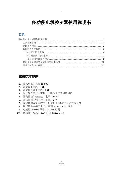
多功能电机控制器使用说明书目录多功能电机控制器使用说明书 (1)主要技术参数 (1)系统硬件构造 (2)伺服软件系统构造 (6)PID算法设计思路 (6)PID滤波器C语言代码 (7)系统通信局部软件设计 (9)使用快速原型系统调试系统的根本思路 (10)驱动器外壳加工问题 (11)主要技术参数1.输入电压:直流18-60V2.最大输出电流:10A3.最大峰值输出电流:20A4.限位输入形式:霍尔开关限位滑动变阻器限位5.开关量输入输出接口电平:5V TTL6.开关量输入输出接口数量:8个7.编码器输入接口种类:相位相差90度的双路方波信号8.编码器输入接口电平:兼容3.3V,5V TTL电平9.电机驱动PWM频率:1K-72K可调10.通信接口形式: CAN总线RS232总线系统硬件构造核心控制电路硬件构造USB和以太网由于空间现在本系统中功能被屏蔽。
USB接口可以实现系统的在线更新和维护。
基于实时以太网的高速控制器为伺服电机控制器开展的趋势〔西门子和法兰克的数控系统都采用这种方式〕,对于分散式控制系统,这种控制方式可以省略掉入XX控制系统中购置多串口卡的本钱;并且,由于网络变压器的隔离特性,即使下层电路在未来的设计中不采用隔离设计,整个系统对于工业控制计算机仍然是隔离的,实用此种方法可以提高系统的稳定性,降低整个系统的本钱,并实现控制系统固件库的在线远程更新。
以上两种功能可以在新的电路板设计中增加。
系统的多功能输入输出构造中预留绝对式磁栅编码器的接口单元。
启动模式根据使用说明书在系统的默认条件下,从主储存器启动,即BOOT0引脚位低,这种情况适合系统通过仿真器调试时使用。
这种启动模式也是默认值。
即在电路板中左部的BOOT0和BOOT1不连接任何短路冒。
这样设计的目的是要早工业应用场合防止使用短路冒造成系统在震开工况下不稳定的情况。
如图1.1 所示。
图1.1 从主FLASH启动的默认设置如果系统需要有在线更新功能,本主控板可以通过USART2,USB OTG FS对系统进展更新。
交流电机控制器使用说明书
交流电机控制器使用说明书 SQ-02系列威海同泰赛维电子科技有限公司地址:高技术产业开发区科技路188号电话:0631-5690236传真:0631-5695057网址:一、基本功能SQ-02型交流电机控制器是针对平面磨床工作台的横向进给电动机设计的,其基本特点如下:1、采用先进的单片机作为控制中心,精度高,调节方便;2、兼有手动连续进给和自动点动进给功能;3、“手动开关”接通时,电机连续进给,直到该开关断开为止;4、“自动开关”点动闭合(约10MS)时,延时TDELAY时间,电机自动进给TADJ时间后自动关闭.5、设有TADJ时间设定拨码开关,可按要求设置进给时间.6、控制精度高(TADJ时间控制精度达1MS)、调节方便、性能可靠、安装调试方便。
7、面板设置状态指示灯,可以准确指示工作状态,并可根据指示灯的状态排除一些简单故障.二、技术参数1、控制器电源电压:AC220V±10%2、电动机输入电压:AC 220V~380V3、最大输出电流:AC 1A4、点动动作时间TADJ:0~200MS~500MS~1000MS~1500MS5、点动延时时间TDELAY:0~500MS三、安装、调试与维修1、对交流电动机的要求1.1电气参数与控制器相匹配1.2线圈内部无匝间短路及开路现象1.3用500v兆欧表测量,电动机对地绝缘电阻应不低于1MQ2、接线及调整方法(参见外接线图,端子号码印于面板上)2.1接线方法:该控制器用于控制三相220V交流电机1#2#3#:外接47K电位器:4#5#:接手动开关:5#6#:接自动开关:7#8#:接两相AC220v输入;9#10#:接负载电机的两相(有一根交流220v相线不经控制器直接进入负载电机);11#:接线端子.注意:如果点动动作时间TADJ调节方向反,请把调节电位器的1#3#线调换.2.2外形及安装尺寸外形尺寸:162(长)×85(宽) ×83(高)安装孔距离:153×452.3动作时间TADJ设置注意:设置某一开关为ON时,其他开关必须置OFF.否则执行最小设定值。
步进电机控制器说明书
步进电机控制器说明书步进电机控制器说明书一、产品概述本文档旨在提供有关步进电机控制器的详细说明。
步进电机控制器是一种用于控制步进电机运动的装置,通过电子方式驱动步进电机实现精确的位置控制。
本控制器具有高精度、可编程性强等特点,适用于各种不同的步进电机应用场景。
二、产品特性本节介绍步进电机控制器的主要特性和功能。
2.1 高精度驱动步进电机控制器采用先进的驱动技术,能够实现高精度的步进电机驱动,可满足精密定位和运动控制需求。
2.2 可编程控制控制器内置丰富的控制算法,支持用户编程,可以根据具体应用需求进行自定义控制,提供更灵活的控制方式。
2.3 多种通信接口本控制器支持多种通信接口,如RS232、RS485、CAN等,便于与其他设备进行通信,实现系统集成和数据传输。
2.4 多种操作模式控制器提供多种操作模式选择,如速度控制、位置控制、力控制等,适应不同应用场景的需求。
2.5 安全保护功能为了确保系统的安全性,本控制器内置了多种安全保护功能,如过流保护、过热保护等,提供有效的保护措施。
三、产品安装和连接本节介绍步进电机控制器的安装和连接方式。
3.1 安装首先,确保电源已经断开。
将控制器固定在合适的位置,通过螺丝固定。
确保控制器和其他设备之间的空间足够,并保持良好的通风。
3.2 连接根据具体应用需求,通过合适的连接线将控制器与步进电机、电源等设备连接。
注意连接的正确性和稳定性,避免接触不良和短路等问题。
四、控制器编程及操作指南本节介绍步进电机控制器的编程和操作方法。
4.1 控制器编程步进电机控制器支持多种编程方式,如C语言、Python等。
用户可以编写相应的代码实现对步进电机的控制和驱动。
4.2 控制器操作指南控制器提供用户友好的操作界面,通过按钮、旋钮等方式进行控制操作。
用户可以根据界面上的指示进行相应的参数设置、模式切换等操作。
五、常见问题与解答本节了一些常见问题,并提供相应的解答。
如果用户遇到其他问题,建议参考本节解答,若问题仍未解决,可联系技术支持人员。
- 1、下载文档前请自行甄别文档内容的完整性,平台不提供额外的编辑、内容补充、找答案等附加服务。
- 2、"仅部分预览"的文档,不可在线预览部分如存在完整性等问题,可反馈申请退款(可完整预览的文档不适用该条件!)。
- 3、如文档侵犯您的权益,请联系客服反馈,我们会尽快为您处理(人工客服工作时间:9:00-18:30)。
电机控制器的说明书
电机控制器是一种电气设备,它主要用于控制电动机的起停、转向、调速和保护等功能。
本说明书将详细介绍电机控制器的使用、安装和
维护保养等方面的内容。
一、使用前须知
1. 本产品应由专业人员使用,如需安装、调试、维修和保养等操作,请确保操作人员具有相关资质、技能和经验。
2. 在运输和使用过程中,应严格按照使用说明书操作,避免因误
操作而造成设备损坏和人员伤害等事故发生。
3. 如需使用电机控制器进行控制,应先了解电机的工作原理和技
术要求,保证电机能正常运转。
二、产品特点
1. 本产品具有精准的控制性能,可满足不同电机的控制需求,如
转速、扭矩、电流等。
2. 本产品集成度高,功耗低,体积小巧,安装操作方便。
3. 本产品设计人性化,界面友好、操作简单。
三、操作说明
1. 接线:将电机控制器与电机之间的电缆连接好,确保接线牢固
可靠,线路接线正确。
2. 调试:在接线完成后,应根据需要设置控制参数,如转速、扭矩、电流等,通过控制器的操作面板进行设置,或通过电脑等外接设备进行调试。
3. 启停:在完成接线和参数调试后,可使用电机控制器进行启停操作,启动电机时应注意安全,如发现异常情况应立即停机检查。
4. 调速:电机控制器可实现电机的调速功能,可以根据需要进行转速调节,以满足生产、加工等的要求。
四、安装注意事项
1. 安装电机控制器应在通风良好、温度适宜的环境下进行。
2. 电机控制器应安装在防止扰动和电磁干扰的环境中,确保其正常工作。
3. 安装位置应考虑到电缆长度、通风、维护保养等方面的因素,应选择安装方便、操作、维护方便的地方。
4. 安装时应注意保护好电机控制器的触点和接线端子,防止其受到损坏或松动。
五、维护保养
1. 每隔一定时间应定期对电机控制器进行检查和维护,如清洁、紧固和调整等。
2. 如出现异常情况应及时排除,可根据使用说明进行故障排除,或联系售后维修部门进行处理。
3. 保养时应注意断电,防止电机控制器被误操作而导致故障。
六、注意事项
1. 本产品为高压电器,操作时应遵守相关规定,防止触电或电气火灾等事故发生。
2. 本产品为机电设备,使用和维护时应注意安全,避免因操作不当而造成人员和设备损伤。
3. 如需更换电机控制器配件,请使用原装件进行更换,避免使用不合适的配件造成设备故障。
七、售后服务
1. 本产品提供售后服务保障,如出现质量问题或使用故障,请及时联系售后服务部门,我们将在第一时间为您提供优质的售后服务。
2. 为了更好的维护您的设备,请保留好本说明书。
如果您需要进一步的咨询或帮助,请联系我们的售后服务部门,我们将尽快为您解决问题。
以上是本产品的说明书内容,希望能对您有所帮助。
如有疑问,请联系我们的售后服务部门。