dbx266XL双通道压缩器中文说明书
最新dbx处理器中文说明书

DBX DriveRack PA数字音频工作站(中文操作手册)0.1 Drive Rack PA的定义dbx Drive Rack PA是控制扩声系统的扬声器各方面最有效的手段,该仪器成为混频器和功放间唯一必需的设备。
以下是该设备的一些特征:●用12个反馈切口过滤器进行立体声反馈消除●双28波段图解式的均衡●经典的DBX压缩机●120A分谐波合成器●2*3、2*4、2*5、2*6交叉配置●立体声多滤段限定均衡●立体声输出限制器●线性延时●粉红噪声发生器●自动均衡(28波段RTA)●JBL音箱和CROWN功放调节安装向导●25个用户程序/25个厂方程序●2个XLR输入和6个XLR输出●前控制面板RTA-M XLR 幻像电源输入●24比特ADC/24比特DAC,大于110dB的动态范围●TypeIV 变换系统●全部图解式的液晶显示第一部分1.1 后面板连接IEC电源容量Drive Rack PA电源可接受100-120V,50HZ-60HZ的范围。
一条IEC线包含在其中。
EU 类型的可接受220-240V,50HZ-60HZ。
1-6输出输出部分提供6个平衡的XLR接口1-2输入输入部分提供2个平衡的XLR接口+4/-10dBv 开关这个开关可+4dBv、-10dBv两档接地提升开关该开关可提升XLR输入插脚1的机架接地1.2 前面板连接RTA输入口这个平衡的XLR输入口是用来连接一个RTA话筒的,它允许用户优化平衡设置,用户可以使用自平衡的向导安装辅助。
RTA话筒输入选择器按下RTA话筒输入键将前面板RTA输入XLR接口数据选择钮数据选择钮用来在程序菜单中滚动选择,加载程序、选择范围和修改范围值。
LCD液晶显示有背景光的液晶显示提供给用户全部的操作信息包括:信号线路,有效限制修改和向导安装功能。
如果任何内部削波在内部单元发生,显示屏同样会提醒用户,以下的信息将出现:削波。
功能键功能键可以让用户直接进行所有修改和导航功能,按钮的功能如下:〈PREV PG〉用来向后引导不同部件单元块〈NEXT PG〉用来向前引导不同部件单元块〈EQ〉用来切换EQ单元,可以让你从输入部分的EQ单元到输出部分的EQ单元〈SUBHARMONIC〉这个按钮用来切换至分谐波合成模式〈XOVER〉用来进入交换模式〈FEEDBACK〉启用反馈消除模式〈COMP/LIMITER〉用来转换压缩或限制模式〈DELAY〉用来切换至延时模式〈PROGRAM〉按下后进入程序模式〈UTILITY〉用来存取“UTILITY实用程序”菜单〈STORE〉存储任何程序变动〈WIZARD〉用来进入向导部分,包括:系统安装、自平衡向导及高级反馈抑制向导。
Galaxy DSPOT 双通道压缩器限制器用户手册说明书
DS-CP22 USER’S MANUALDIGITALContentsIntroduction (1)Safety Instructions (2)Overview........................................................................................ 3 - 8Getting Started with Front Panel Controls.................................... 9 - 24Using the PC Interface.................................................................. 25 - 33Input Meter Table......................................................................... 34 & 35Comp/Limiter Activity Meter Table (36)Block Scheme (37)Specifications (38)IntroductionThank you for choosing a Galaxy DSPOT Digital Signal Processor. You have joined hundreds of thousands of other satisfied Galaxy customers. Since 1977 Galaxy Audio’s professional experience in design and manufacturing ensure our products' quality, performance and reliability.For the most up to date manual and informationvisit .Safety InstructionsThis symbol indicates that dangerous voltage Constituting a risk of electric shock is present within this unit.This symbol indicates that there are importantOperating and maintenance instructions in theLiterature Accompanying This UnitUNPLUG this apparatus during lightning storms or when unused for long periods of12.13.OverviewBelow are the controls and functions of the front panel control buttons and encoders for the DS-CP22.2 - Button Compressor IN/OUT: RMS Compressor Active/Bypass3 - Output Level: Analog Output Volume Left/Right4 - LCD Display5 - LED Clip: Input/Process Overflow6 - Enc Parameter: Adjust Parameters Value7 - Enter Key: Access to Editing Pages and Parameter Values Confirm8 - Enter LED Indicator9 - Enc Navigation: Compressor's Ratio and Knee selection10 - Escape Key: Exit from Editing Pages11 - Escape LED Indicator12 - Power LED13 - PowerThe DS-CP22 is a Stereo RMS Compressor and Peak Limiter with the addition of a Noise Gate, an AGC, a 7 bands Eq and a Sub Harmonic Synthesizer.With reference to the following RMS Compression process representation:The DS-CP22 implements a REAL RMS Compressor, compressing a pure sinusoidal signal at the same threshold as a squared wave.Particularly, the RMS Compressor is a Compression process applied with fast Slow Attack and Release times to the INPUT signal of a Unit, in order to maintain the amplitude of the OUTPUT signal at a defined level when input level exceeds a defined Threshold.The Compressor implemented in the DS-CP22 reacts to the RMS value of the input signal,resulting in a more musical compression.The DS-CP22 Compressor has adjustable Ratio and Hard/Soft Knee parameters. The input to output ratio is accurate to 0.1dBu.The Hard Knee and Soft Knee allow for instant or gradual compression once threshold is reached. Together with the RMS Compressor, the DS-CP22 also includes 2 very useful Dynamic Processes, An Automatic Gain Controller (AGC) and a Peak limiter.In order to understand the operation of the AGC, please refer to the following graphic:The AGC is an Expansion/Compression process applied with fairly slow Attack and Release times To the INPUT signal, in order to maintain the average amplitude of the OUTPUT signal at a defined level, independently from the averaged amplitude of the input sources.The AGC expands the signal when below the threshold setting, and compresses when above the threshold setting.The process uses RMS levels resulting in a more musical sounding process. The AGC process is useful in maintaining a consistent output level.The Speed and the amount of the Expansion can be defined through the “Exp Time” and“Exp Ratio” parameters. The speed and the amount of the Compression can be defined throughthe “Cmp Time” and “Cmp Ratio” parameters.When the Signal coming out from the AGC process (Output), applied to the AGC input, is above the “Exp Thr” and below the “Thr Hold”, it is expanded up to the max expansion coefficient defined by the Exp Ratio.When the Signal coming out from the AGC process (Output), applied to the AGC input, is above the “Cmp Thr”, it is compressed up to the minimum compression coefficient defined by the“Cmp Ratio”.When the AGC output is comprised within the “Thr Hold” and the “Cmp Thr” Thresholds, no further expansion or compression actions will be taken and the expansion/compression coefficient, will be maintained with its current value.If the averaged AGC output level is “entering” the signal “hold” area coming from theexpansion area, then the Coefficient computed by the AGC for multiplying the input level in order to get the proper output signal, will be higher than one (if the “Exp Ratio” will be set at 1:2), and the coefficient will be lower than one (if the “Cm Ratio” will be set between 2:1 and 16:1) if the Averaged AGC output level is “entering” the signal “hold” area coming from the compression area.The last dynamic process available with the DS-CP22, is a Peak Limiter. This is useful when used before an amplifier to limit the signal to avoid over-driving the amplifier input, or to help protect speakers from excessive level.This kind of Limiter is acting on the Signal Peak detection and therefore the limiting is on the output Peak value.In addition to the Dynamic Processes, in the DP-CP22 there is also a Sub Harmonic Synthesizer available.The Sub Harmonic Synthesizer generates sub Harmonics based on the Harmonic content of the original signal.The amplitude distribution of the generated Sub Harmonics follows the shape of a bandpass filter set on the low part of the band.The peak of this “band pass” filter, is centered on 2 possible frequencies, 60Hz and 90Hz. Setting the filter peak at 60Hz (24-36Hz), the Harmonics added to the original sound will bring a “deep” and very low extra body to the original sound.Setting the filter peak at 90Hz (36-56Hz), the Harmonics added to the original sound will bring a “lighter and more booming” extra body to the original sound.Finally, the DS-CP22 includes 7 bands of equalization:A 1st or 2nd Order Highpass, a 1st or 2nd Order Lowpass, and 5 bands of 1st or 2nd OrderPeaking/Shelving filters.The DS-CP22 has a bypass control which bypasses the entire digital process.Input and Output LevelThe Input and Output levels of the DS-CP22 can be adjusted by Analog Potentiometers.The potentiometers operate in the analog domain before the A/D converter (Input Level) and after The D/A converter (Output Level). There is not an absolute and fixed relationship between the Input and Output Levels and the levels in front of the A/D and after the D/A converters.The figures A and B are show in detail the possible positions of the potentiometers controlling the Analog Input and Output Level.Referring then to the above precise divisions of the available range between the MIN and MAX Position of the potentiometers, the Max Analog Input/Output levels can be understood, so the proper setting for the best use of the RMS Compressor can be found.Figure AFigure B0.5123456789MIN MAX OUTPUT LEVEL1.52.53.54.55.56.57.58.59.50.5123456789MINMAX INPUT LEVEL1.52.53.54.55.56.57.58.59.5Getting Startedexample).From this initial condition, and if an RMS Compressor or a Peak Limiter (or both) are set to be Active, their compression/limiting activity can be seen on the “Compressor Activity” and “Limiter Activity” windows. This is accessible from the Input Level page by rotating the NAVIGATIONInput signal level, and compression depth, refer to the tables.Encoders and ENTER, QUIT buttonsThe DS-CP22 is equipped with 2 Relative Encoders, “PARAMETERS” and “NAVIGATION”. These Encoders are used to navigate the user interface and edit sections of the processor. They allow the User to navigate within the screen for the selection of sub-menus, pages and parameters, and to select the values to be assigned during the editing operations.The “ENTER” and “QUIT” buttons allow the user to confirm or NOT confirm the operations performed by the encoders.Particularly, the “ENTER” button is used to enter the editing pages from the initial Input Level and Compressor/Limiter Activity screens.The “QUIT” button is used to get back from any editing page to those screens.From any one of the Initial windows, the editing menus and pages can be accessed by pressing the “ENTER” button.Once leaving the Input Level and Compressor/Limiter Activity windows, the screen will show on the top row, the currently running preset and name, and on the lower row, the sub-menu for theDS-CP22 functions/parameters access and editing.The available Sub-menus are:˜Load Preset: Loading one of the 32 available presets (16 factory and 16 users)˜Save Preset: Store up to 16 user presets˜Utility Function: Communication Interface setting (USB or MIDI)˜Edit Parameters: Access to the parameters’ editing of all the DS-CP22 processesLoad Preset - this page allows the Loading of a preset program from one of the 16 factory presets (1-16) or from one of the 16 user presets:Preset 16: DeepCmpLoad PresetBy pressing ENTER and rotating the “NAVIGATION” encoder, it is possible to scroll through all current available user presets.Load Preset<Preset:21 AGC_Fat>If the Preset 21 is chosen (AGC_Fat), then pressing the “ENTER” button, the current temporary window will appear,Wait : Loading . . . . . .<Preset:21 AGC_Fat>And the AGC_Fat preset number 21 will be loaded and the sub-menu page will go back to the previous level, updated:Preset 21: AGC_FatLoad PresetSave Preset: this page allows you to store a new preset, up to 16, in the DS-CP22’s memory from location 17 up to location 32, skipping the locations 1 to 16 that are reserved to the Factory presets:Preset21: AGC_FatSave PresetBy pressing the ENTER button and rotating the “PARAMETERS” encoder, it is possible to scroll through the previously saved presets and the available empty locations (identified by “Empty”).If no user presets are stored, the “Save a Program” screen will show empty memory locations for All 17-32 presets as shown in the example below for location 30:Save Preset<Preset:30 Empty >When storing an edited configuration for the DS-CP22, select the location for a preset from the 16 available by using the “PARAMETER” encoder.Edit Name Preset” page.) by using the “PARAMETER”The current position of the cursor is shown by a “blinking underscore”.Utility Functionused for controlling the DS-CP22:original menu.Note: The “QUIT” button, once pressed as many times as necessary, will return to the top LCDLevel, which is the one displaying the Input Level or the Compressor/Limiter Activity.Edit Parameters - in this sub-menu, all the parameters related to the signal processes of theDS-CP22 are available for editing.Pressing the “ENTER” button, the processes can be accessed for editing.With the “NAVIGATION” Encoder, all the processes can be scrolled through and from theIn the Editing Parameters Sub-menu, the available processes are:Routing: Assigns the processor to Channel A, B or A+BInput Gain: Digital control of the Input levelNoise GateA.G.C.Filter 1 – Filter 7: Eq. Filter 1 is selectable as 1st or 2nd Order high-pass or low shelving and the filters from 2 to 7 as 1st or 2nd Order shelving or peaking Sub Harmony: Sub Harmonic Synthesizer centered around 65Hz or 90HzDrive: Signal Control before the RMS CompressorRMS CompressorVolume: Make Up Volume after the RMS Compressor and before the Peak LimiterPeak LimiterMute: Output Channel Muting.In order to edit the parameters of any single process, enter the process editing page by pressing the “ENTER” button and leaving it. Once finished editing, by pressing the “QUIT” button to go back to the Editing Parameters sub-menu and select the new process to edit by scrolling through the processes with the NAVIGATION encoder.Routing - from this page it is possible to assign either one of the 2 inputs of the DS-CP22 to theInput GainNoise GateThresholdOFF, the Noise Gate is just bypassed.Release Time - it is the time taken to un-mute the output once detected again an input signal over the set threshold. It can range from 5ms to 100ms, by steps of 1ms up to 10ms, and of 10ms from 10ms up to 100ms.Attack Timesteps of 0.1 seconds.A.G.C. - from this page it is possible to set the parameters of the Automatic Gain Controller. AGC Bypass - from this screen it is possible to set the AGC On or OFF, so to activate it or notOn/Off.AGC Exp Timeto 1.5s:AGC Cmp TimeSet to 0.5s:AGC Cmp ThrIs set to -3dBu:AGC Thr Hold“Hold” area is set to -40dBu:using the “PARAMETER” encoder to set the value.When the Expansion Ratio is set to 1, actually there is no possibility to expand the signal. Meaning that the signal amplitude can be multiplied for a coefficient not higher than 1.the original one.AGC Cmp Ratio pageIf the Compression Ratio is set to 2 or more, the signal can be expanded up to a min amplitude that is depending from the ratio and can reach 1/16th of the original signal amplitude.Filters 1-7 - the DS-CP22 provides 7 bands Eq. for the adjustment of the Input Signal.The first filter of the Eq. can be selected to be 1st or 2nd Order High-pass or a 1st or 2nd Order Low Shelving. The seventh filter can be 1st or 2nd Order Low-pass or a 1st or 2nd Order High Shelving and the filters from the 2nd to the sixth are Peaking filters.Filter 1 - filter 1 is a filter selectable between a 1st and 2nd Order Butterworth High Pass or a 1st and 2nd Order Low Shelving, or the filter can just be bypassed.The parameters selectable using the NAVIGATION encoder are the following:Type - here the filter type can be selected or just bypassed.Frequency - with the PARAMETER encoder, the frequency of the filter can be set, ranging from20Hz to 20kHz in steps of 1/12Oct.Amplitude - if a Low Shelving filter is selected, you can set the filter’s gain here, ranging from-6dBu up to +6dBu.Filter 2-6 - filter 2-6 are Peaking filters.The parameters selectable using the NAVIGATION encoder are the following:Q-Type - here the filter’s Q can be set ranging from 0.05 up to 2.00 by steps of 0.05.Frequency - with the VARIATION encoder the cutting frequency of the filter can be set ranging from 20Hz to 20kHz by steps of 1/12Oct.Amplitude - here, the filter’s gain can be set, ranging from -6dBu up to +6dBu.Filter 7 - filter 7 is a filter selectable between a 1st and 2nd Order Butterworth Low Pass or a 1st and 2nd Order High Shelving, or the filter can just be bypassed.The parameters selectable using the NAVIGATION encoder are the following:Type - here the filter type can be selected or just bypassed.Frequency - with the PARAMETER encoder the cutting frequency of the filter can be set ranging from 20Hz to 20kHz by steps of 1/12Oct.Amplitude - if a High Shelving filter is selected, here you can set the filter’s gain, ranging from-6dBu up to +6dBu.Sub Harmonic - the Sub Harmonic Synthesizer is a particular process, already introduced in the first part of the manual, that isn’t actually related to the RMS compression one.The Sub Harmonic Synthesizer is intended to be an “extra” process available to the user, where the RMS Compressor is chosen for processing a source addressed to a “background” use, as in clubs. It is possible to have synthesized bass in order to extend the band. Also when themusical program is poor of harmonics in the low frequencies, it can help in improving the quality of the background music and to gain a "heavier" or more vibrant sound.The Sub Harmonic Synthesizer is a process synthesizing the first lower harmonic of the frequencies ranging from 40Hz to 500Hz, detected in the original signal.This means that there in the original signal, are detected frequencies from 40Hz to 500Hz, sub harmonics from 20Hz to 250Hz are generated.Figure FAs can be seen in the Figure F, however, the synthesized sub harmonics are not generated in the Low harmonics’ band with the same amplitude, but with a Peak on 65Hz or on 90Hz and then with decreasing amplitude going up from 65Hz/90Hz to 250Hz and down to 20Hz.This is due to the fact, that to extend the same amplitude to the all sub harmonics generated, would bring a “booming” and “dark” result, where having a Peak on the 65Hz(24-36) or 90Hz(36-56), will leave the max intensity of the synthesized sub harmonics, in correspondence of the original fundamentals, ranging around 130Hz and 180Hz, where typically is the octave used byinstruments such as the Bass or Kick Drum, creating a bigger presence and giving the music that much sought after “punch”.Percentadded to the original Signal.FreqPeak is centered on 65Hz and the max amplitude is +18.6dBu. When 36-56 is selected,the Peak is centered on 90Hz and the Max amplitude is 15.7dBu.DriveDetector.This means the Drive the instead the level “seen” by the RMS level detector.Using the drive, it is possible to get a higher level of compression without changing the input level. In this way, the Drive can extend the compression range 6dB more, or reduce it by 12dB.RMS Compressor - the RMS compressor parameters can be controlled by entering the editing screens and scrolling the parameters with the NAVIGATION encoder and setting them with the PARAMETER encoder:Threshold0.1dBu.RatioH/S KneeSteps of 1%Make Up- within this page, it isthe RMS compressor toPEAK Limiter - the Peak Limiter parameters can be controlled by entering the editing screens and scrolling the parameters with the NAVIGATION encoder and setting them with the PARAMETER encoder.Threshold0.1dBuReleaseand 0.2 from 3s to 5s.AttackMuteUsing the DS-CP22 Software.l Load the Software “SetupDS-CP22V1.0.0” either with the included CD or via the Galaxy Website. l Double click on “Setup”, choose “Run” the software will load.l Go to programs and double click on DS-CP22V1.0.0l Connect the SDS-CP22 with the USB cable to your computer.l Turn on the DS-CP22, the driver software will load automatically.l When the driver has finished loading, click once on “connect”.If you want to continue select “Yes”Choose your connection type.Then Click on Connect.The software will look for active devices and show them in a list.To edit Double click on the desired device in the ID list.The Main Page will load.The device will also be locked out from front panel control at this point.You may choose to “Load Preset from PC”, “Save Preset to PC”, “Store Preset to Device”, “Read Preset from Device”You can name a device by selecting edit device name.From the main page you can choose the section you want to adjust by clicking on the associated block. Once you have accessed the block you can adjust parameters by either using the sliders, arrows, or typing the values in directly.Select the gain block to access the gain and polarity of the inputs.Select the EQ block to access the filters.Select the Compressor Block to access the Compressor page.Select the Limiter Block to access the Limiter page.Select the AGC Block to access the AGC page.Select the Noise Gate Block to access the Noise Gate page.Select the SUB-H Block to access the Sub harmonic generator page.You can copy parameters between channels by selecting the copy channel block and then selecting the source parameters and the destination.In order to properly use the indication of the Input Level Meters, it is necessary to note that the Input level to the DS-CP22 is not considered “absolute” information, due to the fact that before the A/D converter, the absolute Input Level can be “adjusted” by the analog potentiometer “Input Level”.For this reason, the meters of the Input Level Display on the LCD are intended to show the Input Signal Level detected by the DSP after the A/D conversion, considering as 0dBu the Maximum Input accepted and converted by the A/D.On the basis of the above, the following table provides the relationship between the Input Level Meters and the Signal Level in the digital domain, before the DS-CP22 processes, assuming not clipping the Signal after the A/D.Therefore it is important, in order to have reasonable indications from the Input Level meters, to ensure the Input signal isn’t clipped.Remember that the Input Signal Clip is occurring when the Absolute Input Signal exceeds+15dBu (Clip on the Op Amps before the A/D converter), or when the Red Clip LED is On.Setting the DS-CP22 in a “0dBu Path” condition (see the introduction for the 0dBu PathDefinition/setting), the following table shows the relation between the Input Level Meters and the absolute Input Level after the A/D converter and the before the DS-CP22 processes.Refer to the following picture:Meter BarInput Level Clip>0dBu -1dBu 0dBu (Red Clip LED)181716151413121110987654321-3dBu -5dBu -7dBu -9dBu -11dBu -13dBu -15dBu -17dBu -19dBu -21dBu -23dBu -25dBu -27dBu -29dBu -31dBu -35dBuThe following Table shows the relationship between the Input Level Meters and the absolute Input Level after the A/D converter and the before the DS-CP22 processes.The Compressor and Limiter Activity Meters provide information in the same manner as the Input Meters.The following table shows the relation between the Compressor/Limiter Activity bar meter and the depth in dBu of the compression/Limiting action.The displayed Compression/Limiting action is from top to down (in the LCD case, from right to left)Indicating the “reduction” of level operated by the Compression/Limiting Actions.Bar Meter Compression/Limiting in dBuNo Activity0dBu (No Compression/Limiting)1 2 3 4 5 6 7 8 9 10 11 12-1dBu -3dBu -6dBu -8dBu -10dBu -12dBu -14dBu -16dBu -18dBu -20dBu -22dBu -24dBuDS-CP22Processes Block SchemeŸDS-CP22 Technical SpecificationsAnalog Inputs : Balanced 2 TRS/2 XLRAnalog Outputs: Balanced 2 TRS/2 XLRInput Max Levels: +15dB uOutput Max Level: +10dBuTHD+N: <0.01% @ -6dBFS (Bypass)S/N Ratio : >100dBu (Processes in Bypass)Frequency Response : 20Hz – 20kHz +/-0.5dBA/D and D/A Resolutio n: 24bitProcess Resolution : 24x48 bitProcesses : RMS Stereo CompressorPower Supply: 110V/220V (Switchable)2x20 characters LCD display for the Parameters EditingFully remotely controllable by USB or MIDI interfaces Dimensions: 9.25" x 19" x 1.75" (234.95 x 482.6 x 44.45 mm) Weight: 6.3lb (2.86kgs)1-800-369-7768 V02062014Printed in China© Copyright Galaxy Audio 2014WARRANTY Information can be viewed online at/warranty.php THREE YEAR LIMITED WARRANTYSpecifications in this manual are subject to change without notice.For the most up to date manual and informationvisit .DS-CP22。
雅马哈压限器实操解读

dbx266XL 压限器实操解读
2012.05.10
音响调音师(中级班)培训教材
上海文广培训中心
岳阳路44号
雅马哈GC2020C 压限器实操解读
CHANNEL A 左声道
CHANNEL B 右声道
POWER 电源开关
2012.05.10
音响调音师(中级班)培训教材
上海文广培训中心
岳阳路44号
雅马哈GC2020C 压限器实操解读
启动时间: 扩展器/噪声门: 就是指当信号电平超出我们 所设置的阈值电平时,压限 器在多长时间内开始工作, 工作电平指示 调节范围为 0.2~20ms,
单声道 立体声 选择
压限器:是压缩器与限幅器的简称。 压缩器:是一种随着输入信号电平增大而本身增 益减少的放大器。当压缩器的压缩比足够大时压缩器就变为限幅器,限幅器:是一种这样 的放大器,输出电平到达一定值以后,不管输入电平怎样增加,其最大输出电平保持恒定 的放大器。该最大输出电平是可以根据需要调节的。
恢复时间: 调节范围为 50ms~2s。
输入信号 状态指示灯
峰值显示灯 PEAK
压缩器 工作/旁通 选择开关
压缩器 调整到压 缩指示2 只红灯开 始闪亮
扩展器/ 噪声门: 电平调整 Nhomakorabea阈值: 决定了压限 器在多大电平 时开始起作用
压缩比: 与阈值相配 合调整,大 于10:1用于 限幅器。
输入电 平调整
输出电 平调整
dbxDriveRackTMPA处理器中文用户手册

一旦完成了全部连接并给机器加电,可通过DriveRackTMPA的前面板对全部信号途径进行领航。显示器提供从输入到输出的每个信号途径的清晰、简明的浏览。
DriveRackTMPA前面板按RTA话筒输入从左到右按排,XLR输入端作为RTA话筒的输入。
用功放参数设置限幅器防止信号削波和平衡电子分频器的输出电平,根据体验和音乐节目的类型可以寻找需要重新调整的分频器电平。
自动EQ奇才设置
·完成了特定的系统设置后,现在可以处理系统EQ了,自动EQ奇才设置通过产生的粉红
噪声自动调整系统的频率响应和调整图示EQ直到RTA匹配一种被选的频响特性。从
DriveRackTMPA奇才菜单,旋转<DATA>轮直到出现下面的显示:
·根据程序模式按<WIZARD>键,显示屏出现下列信息:
Auto EQ WIZARD
AFS WIZARD
DriveRack PA WIZARD
System Setup
系统设置
·箭头显示被选的奇才(Wizard)设置,选择三个选项中的任何一个,旋转<DATA>数据轮,如果执行系统设置,按<NEXT PG>键或<DATA>数据轮,出现下面的显示:
Select Input as MONO
or STEREO.
>STEREO
Input Setup
·简单地旋转<DATA>数据轮,选择单声道或立体声输入配置。选择输入选项后,按<NEXT PG>键,出现如下显示:
Select GEQ as Dual
DBX MX400XL双通道 reverberation 处理器说明书
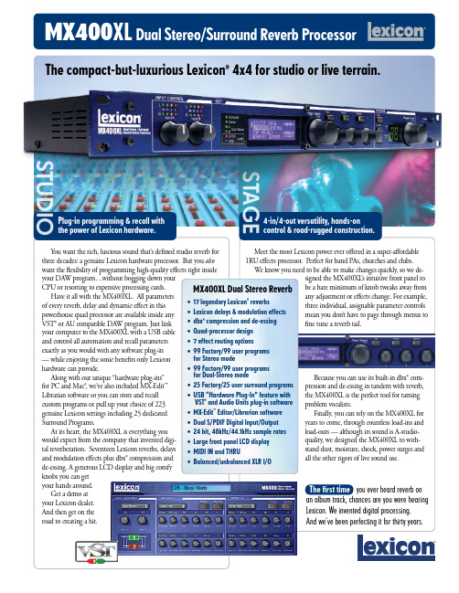
Meet the most Lexicon power ever offered in a super-affordable 1RU effects processor. Perfect for band PAs, churches and clubs. We know you need to be able to make changes quickly, so we de-signed the MX400XL ’s intuitive front panel to be a bare minimum of knob tweaks away from any adjustment or effects change. For example,three individual, assignable parameter controlsmean you don’t have to page through menus tofine tune a reverb tail.4-in/4-out versatility, hands-on control & road-rugged construction.MX400XL Dual Stereo/Surround Reverb ProcessorYou want the rich, luscious sound that’s defined studio reverb for three decades: a genuine Lexicon hardware processor. But you also want the flexibility of programming high-quality effects right inside your DA W program…without bogging down your CPU or resorting to expensive processing cards.Have it all with the MX400XL. All parameters of every reverb, delay and dynamic effect in this powerhouse quad processor are available inside any VST® or AU compatible DA W program. Just link your computer to the MX400XL with a USB cable and control all automation and recall parameters exactly as you would with any software plug-in — while enjoying the sonic benefits only Lexiconhardware can provide.Along with our unique “hardware plug-ins” for PC and Mac®, we’ve also included MX-Edit™ L ibrarian software so you can store and recall custom programs or pull up your choice of 223 genuine Lexicon settings including 25 dedicated Surround Programs.At its heart, the MX400XL is everything you would expect from the company that invented digi-tal reverberation. Seventeen Lexicon reverbs, delays and modulation effects plus dbx® compression and de-essing. A generous LCD display and big comfy knobs you can get your hands around.Get a demo atyour Lexicon dealer.And then get on theroad to creating a hit.Plug-in programming & recall with the power of Lexicon hardware.The compact-but-luxurious Lexicon ® 4x4 for studio or live terrain.MX400XL Dual Stereo Reverb 17 legendary Lexicon ® reverbsLexicon delays & modulation effects dbx ®compression and de-essing Quad-processor design 7 effect routing options 99 Factory/99 user programs99 Factory/99 user programs 25 Factory/25 user surround programs USB “Hardware Plug-In” feature with and Audio Units plug-in software Editor/Librarian software Dual S/PDIF Digital Input/Output 24 bit, 48kHz/44.1kHz sample rates Large front panel LCD displayBalanced/unbalanced XLR I/O•••••••••••••••MX400XL Dual Stereo/Surround Reverb Processor#18-0336Also available: MX400 with balanced/unbalanced ¼" TRS inputs and outputs.— no wall wart!inputs and outputsInput gain level controls. Dual stereo Gain LED ladders.Configuration LEDs.Main LCD screen shows routing configurations, program names, effects and parameters, System settings.Page Select knob for choosing effects & System menus.Exit button.Tempo manually sets delay times.Effect Bypass.Three Parameter adjustment knobs.Program er/Factory program LEDs.System menu access.Stores or copies programs to memory settings.Program/Load selects factory or user programs.Program indicator.stereo to more complex dual stereo configurations, you can have ‘em all at the twist of a knob.Sandy, UT, USA ©2006 All Rights Reserved, HarmanI nternational Industries Inc. Specifica-tions subject to change Lexicon andMX-Edit are trademarks of HarmanInternational Industries, Inc. VST is a trademark of Steinberg Soft- und Hardware GmbH. Mac is a trademark of Apple Computer Corp. P/N 18-0463。
S2-DE_调音台处理器
3 24路调音台 A&H GL2600-424 英国 "24路单声道,2路立体声,4编组,7X4矩阵;内置噪声发生器" 1 台 22000 22000
3 调音台 A&H WZ3 14:4:2 英国 10路单声道、2路立体声输入;立体声输出、4编著输出、6路辅助输出;6*2矩阵 1 台 14127 14127
美国PHONIC品牌大型现场调音台----SONIC STATION系列(性价比较高)
1 调音台 Phonic Sonic Station 32 美国 "26路单声/2路立体声输入(或30路单声道输入、无立体声),内置数字效果处理器调音台,立体声输出、M输出、4编组输出、6辅助输出" 1 台 9130 9130
4 16路调音台 A&H GL2600-416 英国 "16路单声道,2路立体声,4编组,7X4矩阵;内置噪声发生器" 1 台 16500 16500
英国A&H品牌小型现场调音台----PA系列(价格较透明) 台
1 24路调音台 A&H PA28 英国 "24路单声道2路立体声带效果,输出EQ;4辅助输出" 1 台 11000 11000
2 调音台 Phonic Sonic Station 22 美国 "18路单声/2路立体声输入(或20路单声道输入、无立体声),内置数字效果处理器调音台,立体声输出、M输出、4编组输出、6辅助输出" 1 台 6500 6500
Dbx 中文说明书
dbx专业音响产品DriveRack TM PA系统的完全均衡和扬声器控制系统用户手册DriveRack PA目录引言---------------------------------------------------------------3 0.1 Drive Rack TM PA说明---------------------------------------------3 0.2 服务联系信息---------------------------------------------------4 0.3 保证-----------------------------------------------------------4 第一节启动-------------------------------------------------------6 1.1 后面板连接-----------------------------------------------------6 1.2 前面板---------------------------------------------------------6 1.3 快捷启动-------------------------------------------------------8 第二节编辑功能-------------------------------------------------16 2.1 基本领航方式--------------------------------------------------16 2.2 按键配置纵览--------------------------------------------------16 2.3 EQ部分领航(GEQ/PEQ)----------------------------------------17 2.4 分谐波合成器领航----------------------------------------------17 2.5 电子分频器领航----------------------------------------------18 2.6 反馈抑制器领航----------------------------------------------18 2.7 压缩/限幅器领航--------------------------------------------19 2.8 扬声器延时调整领航--------------------------------------------19 2.9 多用途领航----------------------------------------------------20 2.10 奇才程序领航-------------------------------------------------20 第三节Drive Rack PA运行---------------------------------------22 3.1 程序定义------------------------------------------------------22 3.2 工厂程序领航--------------------------------------------------22 3.3 工厂程序编辑--------------------------------------------------23 第四节详细参数-------------------------------------------------25 4.1 前置分频的图像式EQ--------------------------------------------25 4.2 先进的反馈抑制器-----------------------------------------------25 4.3 分谐波合成器---------------------------------------------------27 4.4 分频器------------------------------------------------------27 4.5 后置分频的参数PEQ-------------------------------------------284.6 压缩器/限幅器----------------------------------------------29 4.7 扬声器延时调整----------------------------------------------31 第五节应用指南----------------------------------------------335.12×6 分频器----------------------------------------------33 5.22×5分频器-----------------------------------------------34 5.32×4分频器-----------------------------------------------35 5.42×3分频器-----------------------------------------------35 附录-----------------------------------------------------------37 A.1 重新设置工厂程序-------------------------------------------37 A.2 快捷键的选择-----------------------------------------------37 A.3 技术特性---------------------------------------------------38 A.4 自动EQ的最佳点--------------------------------------------39 A.5 分频器图形-------------------------------------------------40 A.6 方框图-----------------------------------------------------41 A.7 程序表/扬声器调整/功率放大器调整-------------------------42 A.8 系统设置和增益结构-----------------------------------------43 Dbx专业产品登记卡----------------------------------------------46引言用DriveRack TM PA的全部均衡和扬声器控制系统把PA系统驱动到完全新的表演水平。
Drawmer DRAWMER S2 双通道真空管压缩器操作手册说明书
DRAWMERS2Dual ChannelVacuum Tube CompressorOPERATOR’S MANUALCONTENTSWarranty Safety Consideration Chapter 1 - IntroductionIntroduction Installation Audio ConnectionsPower Connection Chapter 2 - Control DescriptionControl Description Quick Setup Procedure Chapter 3 - General InformationIf a fault developsContacting DrawmerSpecification Block Diagram Session Recall Sheet . . . . . . . . . . . . . . . . . . . . . . . . . . . . . . . . . . . . . . . . . . . . . . . . . . . . . . . . . . . 2. . . . . . . . . . . . . . . . . . . . . . . . . . . . . . . . . . . . . . . . . . . . . . . . 2 . . . . . . . . . . . . . . . . . . . . . . . . . . . . . . . . . . . . . . . . . . . . . . . . . . . . . . . 3 . . . . . . . . . . . . . . . . . . . . . . . . . . . . . . . . . . . . . . . . . . . . . . . . . . . . . . . . 4. . . . . . . . . . . . . . . . . . . . . . . . . . . . . . . . . . . . . . . . . . . . . . . . . 5 . . . . . . . . . . . . . . . . . . . . . . . . . . . . . . . . . . . . . . . . . . . . . . . . . 5. . . . . . . . . . . . . . . . . . . . . . . . . . . . . . . . . . . . . . . . . . . . . . . . . 6. . . . . . . . . . . . . . . . . . . . . . . . . . . . . . . . . . . . . . . . . . . . . 9 . . . . . . . . . . . . . . . . . . . . . . . . . . . . . . . . . . . . . . . . . . . . . . . . . 10 . . . . . . . . . . . . . . . . . . . . . . . . . . . . . . . . . . . . . . . . . . . . . . . .10 . . . . . . . . . . . . . . . . . . . . . . . . . . . . . . . . . . . . . . . . . . . . . . . . . . . . .10 . . . . . . . . . . . . . . . . . . . . . . . . . . . . . . . . . . . . . . . . . . . . . . . . . . . 11. . . . . . . . . . . . . . . . . . . . . . . . . . . . . . . . . . . . . . . . . . . . . 132DRAWMER S2 O PERATOR’S M ANUALCHAPTER 1DRAWMERS2DUAL CHANNEL VACUUM TUBE COMPRESSOR ArrayINTRODUCTIONThe new S2 Signature Series Dual Channel Tube Compressor is the latest product to emerge from Ivor Drawmer’s high end designs and offers an ‘all tube - no technical compromise’ circuit using only the highest grade components. The S2 features a host of new creative processing possibilities never before found in an all analogue dynamics package.BIG- Retains bass frequencies and minimizes undesirable ‘pumping’ by rolling off the detection signal at 75, 125 or 250Hz (user switchable). A fully variable level control allows for the desired amount of Big processing and an in/out switch provides the option to remove from the signal path for A/B comparison.BRIGHT- A dynamic high frequency enhancer to keep compressed audio sounding fresh and bright with continuously variable frequency control (500Hz to 20kHz) and amount of dynamic enhancement.DRY- Mixes user defined amount of ‘uncompressed’ signal with the compressed signal to create ‘parallel compression effect’ without the need for external mixing devices.• 2 CHANNEL SOFT-KNEE TUBE COMPRESSOR• FULLY BALANCED INTERNAL SIGNAL PATH• CLASS A DESIGN• ISOLATION TRANSFORMERS IN AND OUT• ‘ALLTUBE’ CIRCUIT DESIGN• VARIABLE ATTACK AND RELEASE WITH OPTIONAL ‘PROGRAMMEDEPENDENT’ AUTO RELEASE OPERATION• DUAL MONO OR STEREO LINK OPERATION• SWITCHABLE ‘PEAK’ OR ‘VU’ METERING TO DISPLAY TRANSIENTS• SWITCHABLE +10dB OR +20dB METER RE-SCALE MODES• 8 SEGMENT GAIN REDUCTION METERING• ‘VARIABLE-BIG’ MODE FOR RETAINING LOW FREQUENCIES• ‘VARIABLE-AIR’ MODE FOR ENHANCING HIGH FREQUENCIES• ‘DRY’ MIX MODE FOR ‘PARALLEL COMPRESSION EFFECT’• BALANCED XLR INPUTS/OUTPUTS3DRAWMER S2 O PERATOR’S M ANUAL4DRAWMER S2 O PERATOR’S MANUALThe S2 is designed for standard 19" rack mounting and occupies 3U of rack space. Fibre or plastic washers may be used to prevent the front panel becoming marked by the mounting bolts. Always connect the mains earth to the unit.Because the S2 contains six valves it will generate more heat than a simple solid state unit. Avoid mounting theunit directly above power amplifiers or power supplies that radiate significant amounts of heat. In addition it is advised that you leave at least 1U of space above to allow heat to dissipate. Alternatively, a fan should be fitted somewhere near to the rear of the unit to circulate cooler air and help expel any excess heat. (see fig. 1)INSTALLATIONfig.2 TYPICAL S2 SETUPfig.1 RACK MOUNT POSITIONING5DRAWMER S2 O PERATOR’S M ANUALThe unit will have been supplied with a power cable suitable for domestic power outlets in your country.For your own safety it is important that you use thiscable. The unit should alwaysbe connected to themains supply earth using this cable, and no other.If for some reason the unit is to be used at a mains input operating voltage which is different to that as supplied, the following procedure must be carried out.1: Disconnect the unit from the mains.2: Remove the two screws holding the voltage selection cover-plate.3: Remove the cover plate and slide the switch fully to its opposite end.4: Rotate the cover plate one half turn (180 degrees)and refit the two screws.5: Replace with a correctly rated fuse for the selected operation voltage in the IEC socket:230V-T500mA and 115V-T1Amp6: Re-connect to mains power source.Never disconnect the earth from the mains supplyAUDIO CONNECTIONSThe inputs and outputs are electronically balanced on conventionally wired XLRs (pin 1 screen, pin 2 hot, pin 3cold and XLR shell is connected to chassis). The operating level is nominally +4dBu. Balanced use is recommended.• Interference:If the S2 is to be used where it maybe exposed to high levels of disturbance such as found close to a TV or radio transmitter, we advise that it is operated in a balanced configuration. The screens of the signal cables should be connected to the chassis connection on the XLR connector as opposed to connecting to pin1. The S2 conforms to the EMC standards.• Ground Loops:If ground loop problems are encountered, never disconnect the mains earth, but instead, try disconnecting the signal screen on one end of each of the cables connecting the outputs of the S2 to the patchbay. If such measures are necessary, balanced operation is recommended.POWER CONNECTIONfig.4 Altering the Voltagefig.3 XLR WIRING6DRAWMER S2 O PERATOR’S M ANUALCONTROL DESCRIPTIONCHAPTER 21 MAIN COMPRESSOR CONTROLSThreshold:+20dB - -26dBDetermines the input level above which gain reduction will be applied.In order to provide as transparent processing as possible Soft knee compression takes place for signals exceeding the threshold level by a few decibels, above which level conventional ‘ratio’ compression is applied.Gain Reduction Meter:Eight Leds at 0,-1,-3,-5,-7,-10,-15,-20dBRatio: 1.4:1 - 10:1Sets the final compression ratio that will be applied once the 'soft-knee' region of the threshold control is exceeded.A ratio of 1:1 provides no compression, whereas approaching 10:1corresponds to more of a limiter.Attack:0.2mS - 100mSControls the speed that the compressor responds to signals that exceed the level set by threshold. For most musical uses, an initial attack setting of between 1 and 20 mS is typical and least obtrusive, with slower settings allowing the start of a percussive or transient signal to pass unaltered, before the compressor reacts. However, bringing the level under control quickly, using a very fast attack time, generally gives more natural results on vocals and mixes.Auto Release:Off - 1 - 2When selected, Auto disables the Release control and continually optimises the release times to suit the dynamics of the material being processed - with 1 having a slightly quicker release than 2 to further suit the varied signals. In general, this setting will produce the least obtrusive level control on signals with widely varying dynamics such as complete mixes.Release:0.05S - 2.0SecondsSets the time taken for the signal to return to normal after the input level has fallen below threshold. For most signals setting the realease at around 0.2 to 0.6 seconds is a good starting point. Be careful with very long release settings, the Compressor might never have enough time for a total recovery between the signal peaks. However, if set too fast, the signal may “pump”, which can be used creatively, but is generally undesirable.2 V-BIGUnlike previous Drawmer compressors the S2 V-Big control is fully variable allowing complete and subtle adjustments to the perceived level of bass, and the control of ‘pumping’ and ducking that occurs.Frequency:75, 125, 250 HzSets the frequency that the ‘V-Big’ control operates at, enabling the engineer to target a specific bass frequency.Level:-10 - +10With the control set in a positive position the side chain's sensitivity to low frequencies is reduced, with the result that less gain reduction is applied to those frequencies, creating the effect that the bass is louder or 'bigger'. It also has the benefit of reducing the ducking and pumping effect that occurs by high frequencies being 'pulled down' in sync with the bass, helping to make mix compression much more affable.If set in a negative position the opposite occurs i.e. with bass frequencies being quieter and pumping increased.At the 0 position the ‘V-Big’ control is effectively off.Active:Off - OnSwitches the ‘Big’ control on and off.3 V-AIRV(ariable)-Air is used to manipulate the high end of an audio signal so that it sounds more intimate, detailed and transparent, but without making it sound harsh or introducing any noticeably unnatural artefacts. Cymbals are more vibrant without becoming splashy, and vocals sound more open but without becoming sibilant.On the S2 the ‘V-Air’ section is not just an everyday side chain E.Q. that most compressor’s would incorporate, replacing any dulling of high frequency detail by simply adding gain, but a fully variable dynamic process that works in conjunction with the compressor, giving more ‘brightness’ as and when it’s required. Being full range the S2 will compress quiet high frequencies whenever the low frequencies are being brought under control, resulting ina dulling of these high levels, and in the worst cases, pumping - it is here where the V-Air controls are at their mosteffective. As shown previously, the ‘Big’ section can also improve things.Frequency:500Hz - 12kHzSets the frequency at which the ‘V-Air’ control operates, enabling the engineer to target a specific frequency.Level:-10 - +10At the 0 position the ‘V-Air’ control is off. In a positive position higher frequencies are enhanced, to add definition, particularly to the human voice and accoustic instruments - a negative position has the opposite effect, and may be used to bring back the balance to a mix whose cymbols are too conspicuous, for example.Active:Off - OnSwitches the ‘V-Air’ control on and off.4 DRYDry works by adding the original signal coming into the unit to the compressed signal that has been processed by the S2, effectively reducing the percieved amount of compression taking place. It is easiest to think of it as being similar to a parallel compressor, but with the advantage of being one simple knob. It provides completely variable control over the whole amount of compression taking place without having to alter numerous settings in order to do so.Level:0 - 10At the 0 setting a fully wet (compressed) signal is passed through to the output. As the control is turned up to 10 the dry signal (no compression) is added, thus lowering the percieved amount of compression. Unlike conventional wet/dry mixes the signal is never completely dry, even at 10 there is still a little compression taking place - use the ‘unit bypass’ (section 7) switch for a completely dry signal.Active:Off - OnSwitches the ‘Dry’ control on and off. When ‘off’ the signal is fully ‘wet’ i.e. compressed.7DRAWMER S2 O PERATOR’S M ANUAL5 GAINGain:-10dB - +20dBDuring compression the signal is attenuated, gain may be required to produce the required output level. The amount of gain required in order to bring the signal level to the same is at input is displayed on the G.R. meter.6 STEREO LINKStereo Link:Off - MasterWhen processing stereo signals, the compression settings of both channels should be the same, otherwise the stereo image will wander if one channel receives more compression than the other. When ‘Stereo Link’ is in the side chain follows both channels and forces the compressor to react to whichever of the channels is at the highest level at any given time, processing both signals according to the settings of Channel 1 (Master). The only exception to this are the ‘Gain’ controls, these remain independant - this is in order to provide a level balance between the two channels.7 METERING AND POWERVU Meters:Two moving coil VU meters monitor the level of the output signal of each channel.Pad:Vu - +10dB - +20dBA three-position switch adjusts the meters to show either normal output level, (and for those working at ‘hot’ outputlevels) VU +10dB or VU +20dB modes. i.e. with the switch at VU +10dB - when the VU meter reads 0dB the actual level is +10dB.Response:Peak VU - VUOn smooth, gentle pieces of music the “VU” (average level) setting would be sufficient, however, on fast dynamic signals the “Peak VU” setting provides more accurate readings.Bypass:Off - OnA fully balanced hard-wire unit bypass connects the input directly to the output, enabling an instant wet/dry comparison.Note: in bypass the VU meters display the levels as though the unit is still compressing. This has been implemented to provide the user with optimum control of the meters.Temperature LedThe S2 is at optimum temperature when the front panel LED indicator is lit, i.e. after the soft start and when the valves have reached optimum temperature - this may take a few seconds.Power:Off - On8DRAWMER S2 O PERATOR’S M ANUAL9DRAWMER S2 O PERATOR’S M ANUALQUICK SETUP PROCEDUREPlease note that the following procedure is only a guide. All audio is different, requiring numerous settings, however,this should give a good staring point:For single channel use, each channel may be considered as being completely independent and set upaccordingly. For use with stereo signals such as complete mixes or submixes, the S2 should be switched to Stereo Link mode and all setting up done using the left hand channel controls.To begin set the compressor controls as above - Threshold fully anti-clockwise, Ratio set to 2:1, the Attack in a mid position (around 20mS) and the Auto Release switch to 1, with Gain at 0dB.V-Big , V-Air and Dry can be bypassed for the time being.Keeping an eye on the Gain Reduction Meters alter the Threshold control for each channel to a level that ‘triggers’ the compressor, and then adjust the the Ratio until the desired compression level is achieved - as a rule,higher ratios provide a higher degree of control but also tend to be more audible in operation when high levels of gain reduction are required - a G.R. level up to -10dB is pensate for the overall drop in output caused by the compression by adjusting the Gain control until 0dB is reached on the Output VU meter (more if in +10dB VU or +20dB modes).Set the Attack knob according to the speed of the audio being processed. It is recommended that the Auto Rel.switch remains on, as it adapts dynamically to the audio, however, if manual release is preferred set the Auto Rel.switch to off, and adjust the Release control. Bear in mind that too short a release time will result in pumping.At this point the Bypass switches can be toggled to listen to the affect that the S2 is having on the audio. Repeat steps 2,3 and 4 to suit.V-Big can now be introduced - set the switch to your target frequency , and rotate the level control until the desired amount of bass is reached.To improve the audio at higher frequencies use the V-Air section, setting the controls in much the same way as V-Big - adjust to suit your taste.The S2 is now basically set up, however, further control is provided via the Dry section. With the switch active,rotating the level control clockwise adds the original, uncompressed signal to the compressed, effectively reducing the percieved amount of compression taking place. Using Dry can bring even the most severely compressed audio under control - again, adjust to suit your own taste. The Gain control may need to be adjusted to bring the output to a suitable level.1)2)3)4)5)6)7)8)9)OPFo use setSe the con hig pro ratIf t co red red coCo qu higAt lon is o attTh occCo exa cau sou to d inc ga us miAt ob thr po an theBe res thr coFin ou On pe enIf r ha effclo10DRAWMER S2 O PERATOR’S M ANUALCHAPTER 3IF A FAULT DEVELOPSFor warranty service please call Drawmer Electronics Ltd. or their nearest authorised service facility, giving full details of the difficulty.A list of all main dealers can be found on the Drawmer webpages.On receipt of this information, service or shipping instructions will be forwarded to you.No equipment should be returned under the warranty without prior consent from Drawmer or their authorised representative.For service claims under the warranty agreement a service Returns Authorisation (RA) number will be issued.Write this RA number in large letters in a prominent position on the shipping box. Enclose your name, address, telephone number, copy of the original sales invoice and a detailed description of the problem.Authorised returns should be prepaid and must be insured.All Drawmer products are packaged in specially designed containers for protection. If the unit is to be returned, the original container must be used. If this container is not available, then the equipment should be packaged in substantial shock-proof material, capable of withstanding the handling for the transit.CONTACTING DRAWMERDrawmer Electronics Ltd., will be pleased to answer all application questions to enhance your usage of this equipment. Please address correspondence to:Drawmer (Technical Help line)Coleman Street Parkgate Rotherham S62 6EL UKAlternatively contact us by E-mail on :forsalesenquiries:*****************orfortechnicalissues:****************Further information on all Drawmer dealers, Authorised service departments and other contact information can be obtained from our web pages on:GENERAL INFORMATIONINPUTInput Impedance 600 Ohms or greater Maximum Input Level+30dBuOUTPUTOutput Impedance 600 OhmsMaximum Output Level+30dBu @ 10k Ohms Load +26dBu @ 600 Ohms LoadFREQUENCY RESPONSE<24Hz to 38kHz -1dB <10Hz to 60kHz -3dBCROSSTALK< -80dB @ 10kHz < -74dB @ 20kHzNOISE AT UNITY GAINwith flat EQ response switched in circuitWideband 22Hz - 22kHz A V-79dB -84dB -87dB-94dBS2 DUAL CHANNEL VACUUM TUBE COMPRESSORDATA SPECIFICATION% DISTORTION (THD & NOISE) @ 1kHz0dB (ref +4)0.03%10dB (ref +4)0.1%20dB (ref +4)0.4%POWER REQUIREMENTS230Volt or 115V at 50-60hZ, 60VAFUSE RATINGT500mA for 230Volt, T1A for 115Volt Conforming to IEC 127-2FUSE TYPE20mm x 5mm, Class 3 Timed-Blo, 250Volt workingCASE SIZE482mm (W) x 132mm (H) x 315mm (D)WEIGHT9.3KgsBLOCK DIAGRAMS2 ver 01 B 26/03/09。
dbx说明
223立体声二分频/ 223立体声二分频/单声道三分频 立体声二分频 224立体声三分频 立体声三分频/ 224立体声三分频/单声道四分频
223立体声二分频/ 223立体声二分频/单声道三分频 立体声二分频 224立体声三分频 立体声三分频/ 224立体声三分频/单声道四分频 • 工作性能 工作性能: 带宽: 频响: 信噪比: 低频输出: 中频输出: 高频输出: 动态范围: 失真+噪声: 通道间串扰:
20Hz – 20kHz,+0/0.5dB <3Hz - >90kHz,+0/-3dB 参考值:+4dBu,22kHz 测量带宽 立体声模式 单声道模式 >94dB >94dB >93dB >92dB >92dB >114dB,未加权,任何输出 <0.004% +4dBu,1kHz <0.004% +4dBu,1kHz <80dB,20Hz-20kHz
200系列电子分频器 系列电子分频器
• 按照专业使用标准来进行设计 通过背版上的开关,可以选择立体声二分频或单声道三分频(立体声二/三分频或 单声道四分频)。背板上还可以选择立体声超低频输出,或是由左右相加合成的 单声道输出。(大多数扩声系统的超低音均是单声道形式,它可充分利用功放, 因为低频是无方向性的)。还可以通过背板上的开关来分别选择两个通道的分频 频率的范围。(x 1)位置让分频点选择45周至960周,(x 10) 位置的分频点范 围改变为450周至9.6千周,当改变了选择时,位于XOVER FREQ旋钮旁的(x 10) 绿色LED指示灯点亮(这样每次使用时,不必检查背板上的开关设定在什么位置 上)。以上的选择开关设定均设在背板上,尽量避免一些非技术人员的错误操作。 前面板有另一些LED指示灯表示单元是处于单声道还是立体声。为了正确设定输 入电平,每组通道上均有输入增益控制。此处还有一个40周的低频切除(高通) 滤波器,消除不需要的低频成分。每个通道均有高、低两组输出,增益的控制范 围从-∞至+6dB,这样可以将某一通道哑音和进行电平匹配。另外,输出设有相位 反转开关这有助于进行系统调整。可以通过内部跳线将相位开关改变为哑音开关。
dbx266XL压限器的使用技巧
dbx266XL压限器的使用技巧一、关于压限器在均衡前、后的问题关于是把压限器放到均衡器前面还是后面,音响界一直以来就在争论不休,“前者”说经过压限器压缩后音乐音色会有些变化,再经过均衡器修饰一下效果就更完美了;“后者”言压限器就是用来压缩强电平信号保护下级设备的,如果把它放在均衡器前面,那万一均衡器调整不当,产生强电平信号后,那此时均衡前的压限器岂不是失去了保护作用?因此要把压限器放在均衡器的后面!看起来都有道理,其实大家何必这么死板呢?如果一套音响系统中只有一台压限器,2台以上均衡器,那在这个系统中压限器当然要放在均衡器前面了,毕竟这样可以保护更多的下级设备;如果一套音响系统中压限器和均衡器数量相当,那在这个系统中压限器当然就要放在均衡器后面了,毕竟这样可以做到:“万无一失”呀!因此灵活运用才是关键。
二、关于压限器的功能现在我们经常使用的压限器一般分为两大主要功能,就是:噪声门、压缩器和限幅器。
A、噪声门1、阈值(THRESHOLD)噪声门顾名思义是可以减少系统中正常噪声的,形象来说它就像一个水库里的水闸,但它拦截的是水底的淤泥。
如果水闸太低,水里的淤泥就会照样越过水闸流向下流;如果水闸太高就不但拦住了无用的淤泥,还拦住了有用的清水。
因此噪声门的门限电平也就是阈值(THRESHOLD)要调到刚刚好,就像水库里的水闸一样要调到合适的高度。
当然为了能完全的把淤泥给拦截掉,我们可以适当提高水闸的高度,这样虽然也拦截掉了一些清水,但也做到了万无一失,相比较来说还是值得的。
2、恢复时间(RELEASE)较长的恢复时间有利于信号的平缓过度,否则恢复时间太短会有突兀感,声音会显得断断续续。
形象的来说:假如我们张开口打个喷嚏,由于从张口到闭口时间很短,所以发出的声音就很突兀,这样的声音就容易让人觉察到;如果我们累了伸伸懒腰长舒一口气,这时你从张开口到闭上口之间的时间较长,如此发出的声音是比较平缓过度的,别人就相对不容易觉察到这种声音。