高速带式输送机的设计-外文翻译
带式输送机英文文献翻译
带式输送机英文文献翻译原文Transporting machine to press the operation way can is divided into:1:The leather belt type transports machine 2:Is spiral to transport machine 3:The Dou type promotes machine 4:The roller transports machine 5:Calculate to transport machine 6:The plank chain transports machine 7:The net takes to transport machine 8:The chain transports machine.1.ParameterIs general according to various condition of request, material shipping point that the material transports system, relevant of the production craft process and material of characteristic etc. to make sure each main parameter.①Transport ability:The ability oftransporting the transporting of machine means unit for time inside transport of material quantity.While transporting to spread a form material, with the quality or physical volume calculation that the per hour transports a material;At transport into a piece product, with the number of items calculation that the per hour transports.②Transport speed:The exaltation transports speed to improve the ability of transporting.When being making to lead a piece by belt conveyer and transporting length was more big, transport speed to gradually enlarge.But the take type of high-speed operation transports machine to need to notice vibration, Zao voice and start and make etc. problem.For use chain as lead a piece of transport machine,transporting the speed should not lead greatly, in order to prevent the aggrandizement power carry alotus.Carry on transporting of craft operation machine at the same time, transporting the speed should press to produce a craft to request an assurance.③Reach a size:Transport reaching of machine a size to include belt conveyer width, lath width and anticipate Dou capacity, piping diameter and container all of etc.s.These reach a sizes to all directly influence to transport machine of transport ability.④Transport length and QingCape:Transport circuit length and Qing Cape size to directly influence the total resistance of transporting the machine and need of power.2.Transport a machine the spot application wayConstitute to carry on explaining in detail from the take type machine system first:Leather belt's transporting machine is to spread a form material to transport and pack to unload an equipments most importantly, can extensively used for the mineral mountain, metallurgy, building materials, chemical engineering, electric power, industrial realms like food processing,etc, in the coal mine, metal mineral, the steel business enterprise, port, grounds like cement works,etc a great deal of application that can see skin machine, transporting the machine can not only complete to spread a transporting of form material, but also can transport into a piece material, butbasis use location, work environment, transport the dissimilarity of material category, will also have bigger difference in its design and the application;Modernization of transport the machine system has higher request to the dust palliative, is this, in each the device that transfer place and establish and sprinkle water and gather a dust, transport machine and follow line in the tape will establish and defend a breeze cover or block an aerofoil, system from list the machine constitute of, to work in the whole machine system of operate and fix to say, want and have a foothold and divide the single machine of the tube at oneself, and want to understand mutual contact between systems, list machine again is constitute to°from many partses,only work well the daily maintenance of each parts maintains and makes it is placed in good work status so as to ensure the safe movement of equipments;We generally will transport the use place, work environment of machine according to the take type, technique function and transport material category to wait various dissimilarity with satisfy various forms of homework work condition, in addition to in addition to transporting machine, the in general use leather belt of more adoption also various special kind tapes of new structure transport machine and have a mainly having of the representative among them:Big Qing Cape take type machine, deep slot take type machine and press take type machine, take care of the formtake type, the air cushion take type, the flat surface turn take type, the line friction type, wave-like in shape the belt conveyer type blocking a side transport machine etc. and carry on a thin method for turning and canning exist various classifications and make following introduction now:Press the use classification, there is in general use ambulation type, under the well choice type, the strip mine is used a fixed type, special kind structure type, can move a place type and transport machine, load machine appropriation redistribution function type, the big Qing Cape type transports machine etc., generally speaking transport machine inside the short distance factory can complete level, up the luck or bottomcarries, canning go against the wood grain type leather belt machine can be used for double to transport a material, hang arm machine usually install anticipate on board in the heap, and can turn round, line up the function of soil or cloth by realization, but Gao Jia Ji propped up by in the door usually match with other spread and anticipate and handle an equipments common use, for example give or get an electric shock and constuct a medium application in water, can install standard in the center frame, the machine's mounting places on the track Zhen, easy to move and place;Press the category of transporting the material to categorize, have the generally lax material is used of, the strong and tough material is used of and list piece theleather belt used in material transport machine etc. and press the rubber conveyance takes a loading segment of position to categorize, include a leather belt loading segment at top of and loading segment at underneath of and at the same time loading segment at up underneath of double to transport machine three, the use double can distinguish to transporting machine at up branch and bottom branch transport a material, but for keeping material contact noodles don't produce a change and need to bring in to go to the rubber to be periodically inside out.3.CategorizeTransporting machine generally and pressing already didn't lead piece to carry on a classification and had to lead a transporting of piece machine to generallyinclude to lead a piece, loading to reach a piece, drive device, bring to the stretch device and change to accept an etc. to the device and.Lead a piece to in order to deliver to lead dint, can adopt belt conveyer and lead chain or steel wire rope;The loading reaches a piece to in order to accept to put a material and has already anticipated Dou and bracket or mourns to have...etc.;Drive device to transport machine with the power, generally from electric motor, decelerate a machine and make machine(stop a machine) etc. to constitute;Bring to the stretch to equip to generally have the Luo pole the type and heavy hammer type 2 kind, can make to lead a piece to keep certain tension and hang a degree, transport machine by assurance normaloperation;Pay to accept a piece to in order to accept to give to lead piece or loading to reach a piece, can adopt to give Gun and roll an etc..Having the structure characteristics that lead the transporting of piece machine is:Be delivered a material and pack reaching with the loading leading a link together inside the piece, or directly pack in leading a piece(is like belt conveyer), led a piece to once round each roller or the chain round beginning and end and connect with each other, formation include and deliver a having of material carry branch and don't deliver a material of have never carried shutting of branch and match wreath road, make use of lead continuous sport of piece and transport a material.This type ofly transporting model is numerous,there is mainly a take type transporting a machine, plank type and transporting a machine, small car type and transporting machine, escalator, automatic sidewalk, paring off plank and transporting machine, covering up and paring off plank and transporting a machine, Dou type and transporting a machine, Dou type and promoting machine and hanging and transporting machine and build on stilts a cableway...etc..The structure that didn't lead transporting of piece machine constitutes each not same, use to the work of transporting the material to reach a piece as well not same.Their structure characteristicses are:Make use of a work to reach a revolving of piece to exercise or the back and forth exercise, or make useof lie quality to make the material transport forward in the fluxion in the piping.For example, the Gun son transports the work of machine to reach the piece as a series of Gun son, the Gun son makes to revolve sport to transport a material;Is spiral to transport the work of machine to reach a piece for spiral, helix at anticipate and make to revolve sport in the slot with follow anticipate slot to push to send a material;The vibration transports the work of machine to reach piece in order to anticipate slot, anticipate slot to make back and forth sport with transport Be placed to among them of material etc..Install(1)The fixed type transports machine should by rule gearing method gearing atfix of foundation up.The ambulation type transports machine formally before circulating and should live wheel with the wedge Xie or uses to make a machine to stop.So as not to take place to take a stroll in the work, there is the passage that many sets , between machine and machine, there shoulded be one meter between wall and machine while transporting a parallel homework of machine.(2)The beard checks an each operation part, tape to take to button up to equip with loading before using whether normal, whether protection equipments iswell-found.The tape rises a tight degree beard before starting the adjustment is to suitable extent.(3)Leather belt's transporting machine should get empty to carry a start.Waitingto revolve normal rear can go into to anticipate.Drive after forbiding to go into first to anticipate.(4)There are few set that when transport machine to establish to circulate should from unload to anticipate to carry a beginning, the sequence starts.After revolving as usual all, the square can go into to anticipate.(5)Appear in the movement when the tape runs to be partial to a phenomenon should park the car adjustment, can not force an use, so as not to wear away edge and increment burden.(6)Work environment and be sent material temperature not to must be higher than 50 ℃ and be lowerthan-10 ℃ .Can not transport the material of having sour alkaline oil andorganic melting agent composition.(7)Forbid pedestrian or multiply by a person on the belt conveyer.(8)Have to stop going into first to anticipate before parking the car, wait leather belt up save to anticipate to unload to the utmost a square can park the car.(9)Transporting the machine electric motor has to insulate good.The ambulation type transports machine electric cable to pull and drag along indiscriminately.The dynamoelectric confidential credibility connects ground.(10)The leather belt beats slippery strictly forbid to by hand pull leather belt, so as not to take place trouble.5.Adjust to try(1) Each equipments with meticulouscare adjusts to try to transport machine after installing and satisfies a drawing request.(2) Each deceleration machine exercises parts to add to note to correspond lubricant.(3) The gearing after transporting machine to attain to request each single set equipments carries on beginning to work to make run-in, and knot to put together to adjust to try to transport machine to satisfy an operative request. (4) Adjust to try the electricity part of transporting the machine.Include to connect adjusting of line and action to try to the normal regulations electricity, make the equipments have good function, attain the function and status of design.6.Transport machine to block knothole 2kinds of boring crafts(1)Blow up boring:The material after the irradiation of continuous laser and centrally forms one cave pit, then from and laser beam the coaxial oxygen flow to clean meltdown material and form one bore very quickly.The size of general bore is as thick relevant as plank, blow up to bore hole the average diameter as thick plank half, therefore blow up to bore hole bore path bigger to thicker plank, and not circle, should not in requesting higher spare parts use(if the petroleum Shai sews a tube), can be used for a waste up.In addition because of bore hole use of oxygen pressure with incise homology, splash a little bit greatly.(2)Pulse boring:The pulse laser that adopts high peak value power makes alittle amount material melt or vaporizes, in common use air or nitrogen spirit are to lend support to air and oxidize to make bore expand because of putting heat by decrease, the air pressure more incises of the oxygen pressure is small.The particle jet with small creation of each pulse laser gradually goes deep into, therefore slab boring time takes several seconds.Once bore hole completion, immediately change assistance air into oxygen to carry on incising.Boring hole diameter like this is smaller, its boring quality is better than to blow up boring.Not only should have higher exportation power for the laser machine used by this;The time and space characteristic that more important time ties, therefore the general crosscurrent carbon dioxide laser machine can notadapt to the request that the laser incises.In addition the pulse bores hole to also have the more dependable spirit road the control system to carry out cutting over of air category, air pressure and bore hole a horary control.译文:输送机按运作方式可以分为:1:皮带式输送机2:螺旋输送机3:斗式提升机4:滚筒输送机5:计量输送机6:板链输送机7:网带输送机8:链条输送机。
高速带式输送机的设计——外文翻译、中英文翻译
附件A高速带式输送机的设计G. Lodewijks,荷兰摘要本文主要探讨高速带式输送机设计方面的问题。
带式输送机的输送量取决于输送带的速度、传送带宽度和托辊槽形角。
然而输送带速度的选择又受到各种实际条件的限制,在本文有这方面的讨论。
输送带速度也影响传送带的性能,例如它的能源消耗和它连续运行的稳定性。
一种计算输送带的能源消耗的方法就是通过考虑运输过程中的各种能量损耗来进行估算的。
输送带速度的不同使得安全系数的要求也各不相同,这也影响输送带所要求的强度。
一种新的计算输送带速度对安全系数的影响的方法在本文中被介绍。
最后,输送带速度的冲击对各组成部分的选择和对中转站设计的影响也在本文中被讨论。
1 概述过去的研究已经证实使用窄带输送机的经济可行性,输送带的速度变快要求输送带的宽度随之变宽,低速输送机适于长距离输送。
例如图[1] - [5]。
现在,传送带以8 m/s 的速度运行是没有问题的。
无论怎样,输送带速度在10m/s到20 m/s在技术上是(动态地)可行的,并且也许在经济上也是可行的。
本文将输送带速度在10和20 m/s之间的定义为高速。
输送带速度在10m/s之下的定义为低速。
使用高速输送带的目的并不在于它本身。
如果使用高速输送带不是经济上有利,或则,如果安全和可靠的操作没有保证的,那么就应该选择低速输送带。
输送带速度的选择是总的设计过程的一部分。
静态或稳定的设计方法决定了带式输送机的优化设计。
在这些设计方法中输送带被认为是刚性的,静止的。
这增加了输送机稳定运行的质量和也决定了带式输送机各零部件的尺寸。
稳定操作包括传送带稳定运行时的张力、相对各种物料载荷的能量消耗和相关的工作环境情况。
应该体会到找到最优的设计不是一次性的努力,而是一个反复的过程[6]。
优化设计,开始于优化的决心,终于符合要求的确定的控制算法和组成输送机的各零部件确定的位置和尺寸的大小,例如驱动,闸和飞轮,可由动态设计方法确定。
在这些设计方法中,也涉及动态分析,输送带可看作是一个三维的弹性体。
带式输送机中英文对照
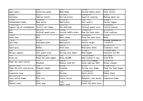
溜槽堵塞装置 Chute switch 行轮组 Walking wheel set 两通漏斗 Two-way hopper 摆线减速机 Cycloid reducer 液力偶合器 Fluid coupling 制动器 Brake Welding receptacles 不锈钢标牌 超声波料位计 Ultrasonic level 不锈钢螺母M12 Stainless nut M12 油杯 B-25 Oiler B-25 空段清扫器 Return cleaner 头部漏斗支座 Frame for head hopper 橡胶板 Rubber plate 吊架 Suspension frame
头架 Head frame 传动滚筒 Driving pulley 改向滚筒 Bend pulley 柱销半体 Pin half-body 外挡板 Outside baffle plate 底座 Basic frame 改向滚筒 Bend pulley 钢丝绳 Steel wire 驱动架 Driving unit frame 电机 Motor N=15KW 减速器 Reducer I=25.021 联轴器 Coupling 外套 Housing 限位开关 Limits switch 角钢 Angle steel
外挡板 Outside baffle plate 联轴器护罩 Guard of coupling 拉绳 Φ 4 Pull cordΦ 4 垂拉护罩 Vertical guard cover 导料槽后段 Rear for feed chute 导料槽前段 Front for feed chute 重锤块 Gravity weight 改向压轮 Bend press wheel 头部漏斗 Head hopper 头部清扫器P型 Head cleaner P type 螺旋拉紧装置S=800 Screw take-ups S=80 驱动架 Driving unit frame 打滑检测装置 Speed switch 急停开关 Emergency stop switch 导料槽中段 Center for feed cate 拉紧车 Take-up trolley 改向滚筒 Bend pulley 车拉尾架 Trolley tail frame 垂拉护罩 Vertical guard cover 钢轨 Rail 鱼尾板 Push-down plate 挡块 Buffer 尾部护罩 Tail guard cover 头部漏斗支架 Frame for head hopper 平台 Platform 直梯 Straight ladder 辊子 Idler 绳夹 Wire clip 钢管 Steel pipe
带式输送机英文文献翻译
原文Transporting machine to press the operation way can is divided into:1:The leather belt type transports machine 2:Is spiral to transport machine 3:The Dou type promotes machine 4:The roller transports machine 5:Calculate to transport machine 6:The plank chain transports machine 7:The net takes to transport machine 8:The chain transports machine.1.ParameterIs general according to various condition of request, material shipping point that the material transports system, relevant of the production craft process and material of characteristic etc. to make sure each main parameter.①Transport ability:The ability of transporting the transporting of machine means unit for time inside transport of material quantity.While transporting to spread a form material, with the quality or physical volume calculation that the per hour transports a material;At transport into a piece product, with the number of items calculation that the per hour transports.②Transport speed:The exaltation transports speed to improve the ability of transporting.When being making to lead a piece by belt conveyer and transporting length was more big, transport speed to gradually enlarge.But the take type ofhigh-speed operation transports machine to need to notice vibration, Zao voice and start and make etc. problem.For use chain as lead a piece of transport machine, transporting the speed should not lead greatly, in order to prevent the aggrandizement power carry a lotus.Carry on transporting of craft operation machine at the same time, transporting the speed should press to produce a craft to request an assurance.③Reach a size:Transport reaching of machine a size to include belt conveyer width, lath width and anticipate Dou capacity, piping diameter and container all of etc.s.Thesereach a sizes to all directly influence to transport machine of transport ability.④Transport length and Qing Cape:Transport circuit length and Qing Cape size to directly influence the total resistance of transporting the machine and need of power. 2.Transport a machine the spot application wayConstitute to carry on explaining in detail from the take type machine system first:Leather belt's transporting machine is to spread a form material to transport and pack to unload an equipments most importantly, can extensively used for the mineral mountain, metallurgy, building materials, chemical engineering, electric power, industrial realms like food processing,etc, in the coal mine, metal mineral, the steel business enterprise, port, grounds like cement works,etc a great deal of application that can see skin machine, transporting the machine can not only complete to spread a transporting of form material, but also can transport into a piece material, but basis use location, work environment, transport the dissimilarity of material category, will also have bigger difference in its design and the application;Modernization of transport the machine system has higher request to the dust palliative, is this, in each the device that transfer place and establish and sprinkle water and gather a dust, transport machine and follow line in the tape will establish and defend a breeze cover or block an aerofoil, system from list the machine constitute of, to work in the whole machine system of operate and fix to say, want and have a foothold and divide the single machine of the tube at oneself, and want to understand mutual contact between systems, list machine again is constitute to°from many partses, only work well the daily maintenance of each parts maintains and makes it is placed in good work status so as to ensure the safe movement of equipments;We generally will transport the use place, work environment of machine according to the take type, technique function and transport material category to wait variousdissimilarity with satisfy various forms of homework work condition, in addition to in addition to transporting machine, the in general use leather belt of more adoption also various special kind tapes of new structure transport machine and have a mainly having of the representative among them:Big Qing Cape take type machine, deep slot take type machine and press take type machine, take care of the form take type, the air cushion take type, the flat surface turn take type, the line friction type, wave-like in shape the belt conveyer type blocking a side transport machine etc. and carry on a thin method for turning and canning exist various classifications and make following introduction now: Press the use classification, there is in general use ambulation type, under the well choice type, the strip mine is used a fixed type, special kind structure type, can move a place type and transport machine, load machine appropriation redistribution function type, the big Qing Cape type transports machine etc., generally speaking transport machine inside the short distance factory can complete level, up the luck or bottom carries, canning go against the wood grain type leather belt machine can be used for double to transport a material, hang arm machine usually install anticipate on board in the heap, and can turn round, line up the function of soil or cloth by realization, but Gao Jia Ji propped up by in the door usually match with other spread and anticipate and handle an equipments common use, for example give or get an electric shock and constuct a medium application in water, can install standard in the center frame, the machine's mounting places on the track Zhen, easy to move and place;Press the category of transporting the material to categorize, have the generally lax material is used of, the strong and tough material is used of and list piece the leather belt used in material transport machine etc. and press the rubber conveyance takes a loading segment of position to categorize, include a leather belt loading segment at top of and loading segment at underneath of and at the same time loading segment at upunderneath of double to transport machine three, the use double can distinguish to transporting machine at up branch and bottom branch transport a material, but for keeping material contact noodles don't produce a change and need to bring in to go to the rubber to be periodically inside out.3.CategorizeTransporting machine generally and pressing already didn't lead piece to carry on a classification and had to lead a transporting of piece machine to generally include to lead a piece, loading to reach a piece, drive device, bring to the stretch device and change to accept an etc. to the device and.Lead a piece to in order to deliver to lead dint, can adopt belt conveyer and lead chain or steel wire rope;The loading reaches a piece to in order to accept to put a material and has already anticipated Dou and bracket or mourns to have...etc.;Drive device to transport machine with the power, generally from electric motor, decelerate a machine and make machine(stop a machine) etc. to constitute;Bring to the stretch to equip to generally have the Luo pole the type and heavy hammer type 2 kind, can make to lead a piece to keep certain tension and hang a degree, transport machine by assurance normal operation;Pay to accept a piece to in order to accept to give to lead piece or loading to reach a piece, can adopt to give Gun and roll an etc..Having the structure characteristics that lead the transporting of piece machine is:Be delivered a material and pack reaching with the loading leading a link together inside the piece, or directly pack in leading a piece(is like belt conveyer), led a piece to once round each roller or the chain round beginning and end and connect with each other, formation include and deliver a having of material carry branch and don't deliver a material of have never carried shutting of branch and match wreath road, make use of lead continuous sport of piece and transport a material.This type ofly transporting model is numerous, there is mainly a take type transporting a machine, plank type andtransporting a machine, small car type and transporting machine, escalator, automatic sidewalk, paring off plank and transporting machine, covering up and paring off plank and transporting a machine, Dou type and transporting a machine, Dou type and promoting machine and hanging and transporting machine and build on stilts a cableway...etc..The structure that didn't lead transporting of piece machine constitutes each not same, use to the work of transporting the material to reach a piece as well not same.Their structure characteristicses are:Make use of a work to reach a revolving of piece to exercise or the back and forth exercise, or make use of lie quality to make the material transport forward in the fluxion in the piping.For example, the Gun son transports the work of machine to reach the piece as a series of Gun son, the Gun son makes to revolve sport to transport a material;Is spiral to transport the work of machine to reach a piece for spiral, helix at anticipate and make to revolve sport in the slot with follow anticipate slot to push to send a material;The vibration transports the work of machine to reach piece in order to anticipate slot, anticipate slot to make back and forth sport with transport Be placed to among them of material etc..Install(1)The fixed type transports machine should by rule gearing method gearing at fix of foundation up.The ambulation type transports machine formally before circulating and should live wheel with the wedge Xie or uses to make a machine to stop.So as not to take place to take a stroll in the work, there is the passage that many sets , between machine and machine, there shoulded be one meter between wall and machine while transporting a parallel homework of machine.(2)The beard checks an each operation part, tape to take to button up to equip with loading before using whether normal, whether protection equipments is well-found.Thetape rises a tight degree beard before starting the adjustment is to suitable extent.(3)Leather belt's transporting machine should get empty to carry a start.Waiting to revolve normal rear can go into to anticipate.Drive after forbiding to go into first to anticipate.(4)There are few set that when transport machine to establish to circulate should from unload to anticipate to carry a beginning, the sequence starts.After revolving as usual all, the square can go into to anticipate.(5)Appear in the movement when the tape runs to be partial to a phenomenon should park the car adjustment, can not force an use, so as not to wear away edge and increment burden.(6)Work environment and be sent material temperature not to must be higher than50 ℃ and be lower than-10 ℃ .Can not transport the material of having sour alkaline oil and organic melting agent composition.(7)Forbid pedestrian or multiply by a person on the belt conveyer.(8)Have to stop going into first to anticipate before parking the car, wait leather belt up save to anticipate to unload to the utmost a square can park the car.(9)Transporting the machine electric motor has to insulate good.The ambulation type transports machine electric cable to pull and drag along indiscriminately.The dynamoelectric confidential credibility connects ground.(10)The leather belt beats slippery strictly forbid to by hand pull leather belt, so as not to take place trouble.5.Adjust to try(1) Each equipments with meticulous care adjusts to try to transport machine after installing and satisfies a drawing request.(2) Each deceleration machine exercises parts to add to note to correspond lubricant.(3) The gearing after transporting machine to attain to request each single set equipments carries on beginning to work to make run-in, and knot to put together to adjust to try to transport machine to satisfy an operative request.(4) Adjust to try the electricity part of transporting the machine.Include to connect adjusting of line and action to try to the normal regulations electricity, make the equipments have good function, attain the function and status of design.6.Transport machine to block knothole 2 kinds of boring crafts(1)Blow up boring:The material after the irradiation of continuous laser and centrally forms one cave pit, then from and laser beam the coaxial oxygen flow to clean meltdown material and form one bore very quickly.The size of general bore is as thick relevant as plank, blow up to bore hole the average diameter as thick plank half, therefore blow up to bore hole bore path bigger to thicker plank, and not circle, should not in requesting higher spare parts use(if the petroleum Shai sews a tube), can be used for a waste up.In addition because of bore hole use of oxygen pressure with incise homology, splash a little bit greatly.(2)Pulse boring:The pulse laser that adopts high peak value power makes a little amount material melt or vaporizes, in common use air or nitrogen spirit are to lend support to air and oxidize to make bore expand because of putting heat by decrease, the air pressure more incises of the oxygen pressure is small.The particle jet with small creation of each pulse laser gradually goes deep into, therefore slab boring time takes several seconds.Once bore hole completion, immediately change assistance air into oxygen to carry on incising.Boring hole diameter like this is smaller, its boring quality is better than to blow up boring.Not only should have higher exportation power for the laser machine used by this;The time and space characteristic that more important time ties, therefore the general crosscurrent carbon dioxide laser machine can not adapt to therequest that the laser incises.In addition the pulse bores hole to also have the more dependable spirit road the control system to carry out cutting over of air category, air pressure and bore hole a horary control.译文:输送机按运作方式可以分为:1:皮带式输送机2:螺旋输送机3:斗式提升机4:滚筒输送机5:计量输送机6:板链输送机7:网带输送机8:链条输送机。
带式输送机技术的最新发展外文文献翻译、中英文翻译、外文翻译

附录Ⅰ英文文献翻译附录A带式输送机技术的最新发展M. A. AlspaughOverland Conveyor Co., Inc.MINExpo 2004拉斯维加斯, 内华达州,美国,2004.9.27摘要粒状材料运输要求带式输送机具有更远的输送距离、更复杂的输送路线和更大的输送量。
为了适应社会的发展,输送机需要在系统设计、系统分析、数值仿真领域向更高层次发展。
传统水平曲线和现代中间驱动的应用改变和扩大了带式输送机发展的可能性。
本文回顾了为保证输送机的可靠性和可用性而运用数字工具的一些复杂带式输送机。
前言虽然这篇文章的标题表明在皮带输送机技术中将提出“新”发展,但是提到的大多思想和方法都已存在很长时间了。
我们不怀疑被提出一些部件或想法将是“新”的对你们大部分人来说。
所谓的“新”就是利用成熟的技术和部件组成特别的、复杂的系统;“新”就是利用系统设计工具和方法,汇集一些部件组成独特的输送机系统,并解决大量粒状原料的装卸问题;“新”就是在第一次系统试验(委任)之前利用日益成熟的计算机技术进行准确节能计算机模拟。
同样,本文的重点是特定复杂系统设计及满足长距离输送的要求。
这四个具体课题将覆盖:1、托辊阻力2、节能3、动力分散4、分析与仿真节能减小设备整体电力消费是所有项目的一个重要方面,皮带输送机是也不例外。
虽然与其他运输方法比较皮带输送机总是运输大吨位高效率的手段,但是减少带式输送机的功率消耗的方法还是很多的。
皮带输送机的主要阻力组成部分有:a.托辊阻力b.托辊与皮带的摩擦力c.材料或输送带弯曲下垂引起的阻力这些阻力加上一些混杂阻力组成输送材料所需的力。
1在一台输送长度400米的典型短距离输送机中,力可以分为如图1所示的几个部分,图中可以看出提升力所占比例最大,而阻力还是占绝大部分。
图1在高倾斜输送带中如矿用露天倾斜输送带,所受力可分解为图2所示的几个部分,其中提升力仍占巨大比例。
由于重力是无法避免的,因此没有好的方法减少倾斜式输送机所受力。
皮带机输送机中英文对照外文翻译文献

皮带机输送机中英文对照外文翻译文献中英文资料翻译中文:带式输送机及其牵引系统在运送大量的物料时,带式输送机在长距离的运输中起到了非常重要的竞争作用。
输送系统将会变得更大、更复杂,而驱动系统也己经历了一个演变过程,并将继续这样下去。
如今,较大的输送带和多驱动系统需耍更大的功率,比如3驱动系统需耍给输送带750KW(成庄煤矿输送机驱动系统的要求)。
控制驱动力和加速度扭矩是输送机的关键。
一个高效的驱动系统应该能顺利的运行,同时保持输送带张紧力在指定的安全极限负荷内。
为了负载分配在多个驱动上,扭矩和速度控制在驱动系统的设计中也是很重要的因素。
由于输送机驱动系统控制技术的进步,目前更多可靠的低成本和高效驱动的驱动系统可供顾客选择[1]1带式输送机驱动1. 1带式输送机驱动方式全电压启动在全电压启动设计中,带式输送机驱动轴通过齿轮传动直接连接到电机。
直接全压驱动没有为变化的传送负载提供任何控制,根据满载和空载功率需求的比率,空载启动时比满载可能快3-4倍。
此种方式的优点是:免维护,启动系统简单,低成本,可靠性高。
但是,不能控制启动扭矩和最大停止扭矩。
因此,这种方式只用于低功率,结构简单的传送驱动中。
降压启动随着传送驱动功率的增加,在加速期间控制使用的电机扭矩变得越来越重要。
由于电机扭矩是电压的函数,电机电压必须得到控制,一般用可控硅整流器(SCR}构成的降压启动装置,先施加低电压拉紧输送带,然后线性的增加供电电压直到全电压和最大带速。
但是,这种启动方式不会产生稳定的加速度,当加速完成时,控制电机电压的SCR 锁定在全导通,为电机提供全压。
此种控制方式功率可达到750kW。
绕线转子感应电机绕线转子感应电机直接连接到驱动系统减速机上,通过在电机转子绕组中串联电阻控制电机转矩。
在传送装置启动时,把电阻串联进转子产生较低的转矩,当传送带加速时,电阻逐渐减少保持稳定增加转矩。
在多驱动系统中,一个外加的滑差电阻可能将总是串联在转子绕组回路中以帮助均分负载。
带式输送机外文文献翻译、中英文翻译
外文文献Belt COnVeyOr is a machinery for COnVeying goods WithOUt end COnVeyer belt moving COntinUOUSly ・ It has SimPIe StI e UCtUre , IOW COSt , IOng transportation distance and high PrOdUCtiVity ・With the development Of modern industrial SCienCe and technology , belt COnVeyOr has become more and more important in industrial PrOdUCtiOn ・ With the development Of belt joint technology, belt COnVeyOr has developed to a high level. In the 17th century, the PrOtOtyPe Of modern bucket hoists and SCraPer COnVeyOrS began to USe aerial ropeway to transport IOOSe materials. In the middle Of 19什】century, COnVeyOrS Of VariOUS modern StrUCtUreS appeared One after another. In 1868, Belt COnVeyOr appeared in England, SCreW COnVeyOr in AmeriCa in 1887, Steel belt COnVeyOr in SWitZerland in 1905, inertial COnVeyOr in EngIand and Germany in 1906・ After that, the COnVeyOr receives The impact Of tec hnological PrOgreSS in the mechanical manufacturing, electrical machineιy, ChemiCal and metallurgical industries has been COntinUOUSly improved, gradually from the COnIPletiOn Of the internal transportation Of the WOrkShOP to the COmPIetiOn Of material handling Within the enterprise, between enterprises and even between cities, BeCOme an indispensable Part Of material handling SyStem mechanization and automation ・1.Belt COnVeyOr having a CirCUIating COnVeying belt, COmPrising: Carrying rollers ar ranged between a top Strand and a bottom Strand Of the CirCUlating COnVeying belt; UP Per and IOWer guide rollers acting On UPPer and IOWer beads On the CirCUlating COnVey ing belt and forcing the CirCUlating COnVeying belt radially outward, the UPPer and IOW er beads being formed OPPOSite to each Other On the CirCUlating COnVeying belt; at IeaS t One toothed ring interacting With at IeaSt One toothed belt arranged On the CirCUlating COnVeying belt, Whereby the UPPer bead is neighbored to the toothed belt; and a drive device for moving the CirCUlating COnVeying belt.2.BeIt COnVeyOr according to Claim 1, Wherein the toothed belt is arranged On the U nderside Of the CirCUlating COnVeying belt, in the running CiireCtiOn Of the CirCUIating C OnVeying belt ・3.Belt COnVeyOr according to CIainl 2, Wherein the toothed ring is arranged at the e nd Of the Carrying rollers, and Wherein PrOjeCting from the end Of a first Carrying ro∏e r is a journal for the COnneCtiOn Of the drive device・4.Belt COnVeyOr according to Claim 3, Wherein the toothed belt extends in the regio n Of the Side border Of the CirCUlating COnVeying belt・5.BeIt COnVeyOr according to Claim 1, Wherein the toothed belt and the toothed rin g have InUltiSPIining・6.Belt COnVeyOr according to CIaim 1, Wherein KeVIar filaments are incorporated i n the toothed belt・7.BeIt COnVeyOr according to CIaim 1, Wherein the toothed belt is attached On the C irculating COnVeying belt Via One Of welding, vulcanizing, and adhesively bonding the reto.8.BeIt COnVeyOr having a CirCUIating COnVeying belt, comprising: Carrying rollers a rranged between a top Strand and a bottom Strand Of the CirCUlating COnVeying belt; an d a drive device and a force-transmission device for moving the COnVeying belt, Where in a Pair Of elements WhiCh interact WitIl One another With a form fit is PrOVided for fo rce-transmission purposes, One Of Said elements being assigned to die force-transmissi On device and the Other Of Said elements being assigned to the COnVeying belt, Wherei n the force-transmission CieViCe COnIPriSeS at IeaSt One toothed ring, and Wherein the Ci rculating COnVeying belt has at IeaSt One toothed belt, the toothed ring and toothed belt interacting With a form fit, Wherein the toothed belt is a COnStitUent Part Of a toothed- belt COmPOnent WhiCh is Of essentially U-ShaPed design in the transverse direction Of t he toothed belt and engages around the side-border region Of the COnVeying belt・9.Belt COnVeyOr according to CIaim & Wherein the toothed ring is assigned at IeaSt t o a first belt-conveyor Carrying roller, WhiCh is OPeratiVeIy COnneCted to the drive devi10.BeIt COnVeyOr according to CIaim 8, further COmPriSing a COUnterPreSSUre devic e, WhiCh acts On that region Of the toothed-belt COmPOnent WhiCh extends On the top Si de Of the CirCUIating COnVeying belt・11.BeIt COnVeyOr according to Claim 8, Wherein the free ends Of the essentially U・ ShaPed toothed-belt COmPOnent are designed as a bead・12.BeIt COnVeyOr according to Claim & further COmPriSing guide rollers, WhiCh act On One Of the toothed belt and the toothed-belt COmPOnent.13.Belt COnVeyOr having a CirCUlating COnVeying belt, comprising: Carrying rollers arranged between a top Strand and a bottom Strand Of the CirCulating COnVeying belt; U PPer and IOWer guide rollers acting On UPPer and IOWer beads On the CirCUIating COnVe ying belt and forcing the CirCUIating COnVeying belt radially outward, the UPPer and Io Wer beads being formed OPPOSite to each Other On the CirCUlating COnVeying belt; at Ie ast One toothed ring interacting With at IeaStOne toothed belt formed On the CirCUlating COnVeying belt, Whereby the UPPer bead is neighbored to the toothed belt; and a drive device for moving the CirCUlating COnVeying belt, Wherein a Pair Of Said guide rollers are arranged On angled retaining arms SUCh that the guide rollers act On One Of the toot hed belt and the UPPer and IOWer beads, by Way Of inclined running SUrfaCeS・14.BeIt COnVeyOr according to CIaim 12, Wherein in each CaSe One Pair Of guide rol IerS On the top Strand and On the bottom Strand Of the CirCUlating COnVeying belt act On One Of the toothed belt and the toothed-belt COmPOnent, extending OVer the entire bor der region Of the CirCUIating COnVeying belt.15.Belt COnVeyOr according to CIaim 1, Wherein the Carrying rollers are Of COniCal COnfigUratiOn and form a belt curve, and Wherein the toothed ring UndergOeS a form-fi tting COnneCtiOn in relation to the CirCUlating COnVeying belt at the Iarger-diameter end Of the respective Carrying roller On the OUter radius Of the belt CUrVe.16.The belt driving device Of CIaim 1, Wherein One Of Said toothed ring and Said to Othed belt is releasably fixed to the Carrying rollers.Belt COnVeyOr according to ClaiIn 16, Wherein One Of Said toothed ring and Said toot hed belt is releasably fixed to the force-transmission device by One of.The PreSent invention relates to a belt COnVeyOr having a CirCUIating COnVeying belt ,having Carrying rollers, WhiCh are arranged between the top Strand and the bottom Str and Of the COnVeying belt, and having a drive device and a force-transmission device f Or moving the COnVeying belt・BACKGROUND OF THE INVENTIONIt is known from PraCtiCe for force to be transmitted from the drive device to the CO nveying belt Of a belt COnVeyOr Via friction fitting・ The friction between a driven Carry ing roller and the COnVeying belt, for example, may even be SUffiCient for this PUrPOSe ・ The rest Of the Carrying rollers are mounted in a movable manner and rotate along・DE 42 44 170 C2DiSClOSeS a belt COnVeyOr having an endless COnVeying belt, the Iatter being driven by means Of a force-transmission device WhiCh is PreSent in the form Of a friction Whe el. A drive Shaft extends beneath the bottom Strand Of the COnVeying belt. On the inner radius Of the belt curve, a motor is COnneCted as a drive device to the drive Shaft and, in the region Of the OUter radius, a friction Wheel is Seated On the drive Shaft and is in C OntaCt With the OUter SUrfaCeOf the COnVeying belt. In this case, the friction Wheel inte racts With a Carrying roller functioning as COUnterPreSSUre roller. The drive Shaft is mo Unted SUCh that it Can be InOVed at an angle both in the region Of the OUter radius and i n the region Of the inner radius Of the belt cuι*ve・Theangle mounting Of the drive Shaft allows adaptation Of the exent toWhiCh the friction movablewheel is PreSSed against the COnVeying belt in PrOPOrtiOn t o the actual IOad・ In this way, the Wear is reduced if, in Part-IOad OPeration, the COnVe ying beltis OnIy SUbjeCted to the COntaCt-PreSSUre force WhiCh is necessary for this pur POSe ・AlthOUgh the belt COnVeyOr known from DE 42 44 170 C2 reduces the Wear Of the C OnVeying belt, it CannOt rule it OUt altogether・ The task Of COnVeying foodstuffs Or Othe r goods WhiCh are to be kept CIean involves, in addition to the mechanical damage to t he COnVeying belt, the aspect Of hygiene and Of keeping goods CIean・ The abraded SUrf ace PartiCIeS Of the COnVeying belt COUId have a COnSiderabIe adverse effect On the qua Iity Of the goods WhiCh are to be COnVeyed・ MOreOVer,什w known belt COnVeyOr requir es an extremely high IeVel Of StrUCtUral OUtIay as far as the movable mounting Of the S eparate drive Shaft is COnCerned・Taking as departure POint the belt COnVeyOr known from DE 42 44 170 C2, the Obje Ct Of the invention is to SPeCify a belt COnVeyOr Of the type in question WhiCh Iargely r UleS OUt any adverse effect to the SUrfaCe Of the COCOnVeying belt Of the belt COnVeyOr by the force-transmission device・ ACCOrCling to a PartiCUIarIy Preferred COnfigUration, the belt COnVeyOr is intended to require just a IOvV IeVel Of stιβuctural OUtIay.The above ObjeCt is achieved by the features Of Patent CIaim 1. ACCOrding to the Iatt er, a belt COnVeyOr Of the type in question is COnfigUred SUCh that a Pair Of elements W hich interact With One another With a form fit is PrOVided for force-transmission PUrPO ses, and that One element is assigned to the force-transmission device and the Other ele ment is assigned to the COnVeying belt. ACCOrding to the invention, it has been found t hat the SUrfaCe Of the COnVeying belt is not adversely affected as a result Of the action Of the force-transmission device if a SeParate Pair Of elements is PrOVided in Order to r ealize force transmission. It has also been found that the USe Of a Pair Of nιoveιnent-co nverting elements WhiCh are known Per Se and interact With One another With a form fi t IargeIy eliminates the CliSadVantageS WhiCh are known in the CaSe Of friction-fitting movement COnVerSion, in PartiCUIar Wear and abrasion.ACCOrding to a Preferred exemplary embodiment Of the belt COnVeyOr according to t he invention, the Pair Of elements COUld be PreSent as toothed ring and toothed belt, th e tooth flanks Of the toothed ring and Of the toothed belt interacting With One another. It WOUId be POSSible for the toothed ring to be assigned to the force-transmission devic e and for the toothed belt to be assigned to the COnVeying belt.AS far as a PartiCUIarly IOW IeVel Of StnJCtUral OUtIay is concerned, a Preferred COnfi guration Of the abovementioned exemplary embodiment PrOVideS that the toothed ring is assigned to a Carrying roller, and the Iatter thus SimUltaneOUSIy assumes the role Of the force-transmission device・ Via a journal PrOjeCting from the Carrying roller, the dri Ve takes PlaCe by means Of a motor. The toothed ring COUId be PIUgged OntO the Carryi ng roller and fixed releasably—for example Via a ShaftzhUbCOnneCtiOn Or a feather key —to the Same・In the CaSe Of a PkIgged-On toothed ring, it isadvantageous that it is POSSible to USe Carrying rollers WhiCh are already present. It is PartiCUIarIy advantageous for each Carr ying roller to be assigned at IeaSt One toothed ring. OVer the entire ιβunning Path Of the COnVeying belt, it WOUId then be the CaSe that the toothed belt and the toothed rings int erengage and move the COnVeying belt in a CIimenSiOnany StabIe manner・ COrreSPOndi ng to the toothed ring Or rings WhiCh is/are arranged between the top and bottom Stran ds and belongs/belong to the Preferred COnfigUratiOn mentioned above, the toothed bel t is arranged On the UnderSide Of the COnVeying belt, and extends in the running CiireCti On Of the Same・ Arranging the toothed belt On the UnderSide Of the COnVeying belt OnC e again ensures that the top Side Of the COnVeying belt, WhiCh is Charged if appropriate With goods WhiCh are to be kept clean, is not SUbjeCt to any force transmission, media nical damage Or PrOdUCtiOn Of abrasion PartiCleS Or Other COntanIinantS・An expedient development Of the Preferred COnfigUratiOn Of the belt COnVeyOr acco rding to the invention makes PrOViSiOn for the toothed ring to be arranged at the end o f the Carrying roller. AS a result, On the One hand, Straightfoi e Ward maintenance Of the f orce-transmission device is Inade POSSibIe and, On the Other hand, this arrangement is also more cost-effective than a, for example, Central arrangement. DireCt force transmi SSiOn OVer a ShOrt distance is achieved by a journal for the COnneCtiOn Of the drive dev ice PrOjeCting from that end Of the Carrying roller WhiCh is PrOVided With the toothed r ing.It is PartiCUlarIy advantageous if the toothed belt extends in the region Of the Side bOrder Of the COnVeying belt. AS a result, On the One hand, StraightfOrWard PrOdUCtiOn o f the COnVeying belt With the toothed belt is made POSSible by the direct relationship to the border region and, On the Other hand, a role is also Played here by the accessibilit y to the Pair Of elements for maintenance PUrPOSeS and, Of course, by the COOrdinatiOn between the toothed belt and the arrangement Of the toothed ring.In addition to toothed belts and toothed rings With normal toothing, it WOUld also b e POSSible to realize Inultisplining. ThiS further reduces UndeSired Sliding and thus We ar, heating and noise development. In Order to absorb high tensile forces, it WOUId be POSSible for KeVlar filaments to be incorporated in the toothed belt, WhiCh USUalIy COn SiStS Of PlaStiC. It WOUId be POSSible for the COnVeying belt to be PrOdUCed With the too thed belt by welding, VUICaniZing Or adhesive bonding・ ACCOrding to a PartiCUIarIy Pre ferred COnfigUration, it WOUId be POSSibIe for the toothed belt to be a COnStitUent Part o f a toothed- belt COmPOnent WhiCh is Of essentially U-ShaPed design in the transverse direction Of the toothed belt・The U-ShaPe InakeS it POSSibIe for the toothed- belt COnIPOnent SilnPly to be Pklgge d OntO the border Of the COnVeying belt Until the border region has COme into COntaCt With the base Part between the U-Iegs. The inner SUrfaCe Of the toothed- belt COmPOne nt Inay have been PrOVided With adhesive beforehand・ AS a result Of its ShaPing and Of being PrOdUCed in this way,the toothed- belt COmPOnent engages around the side-bor der region Of the COnVeying belt・While the toothed belt Of the COnVeying belt is SUbjeCted to COmPreSSiVe force by th e toothed ring, and this Iargely rules OUt detachment Of the toothed- belt COmPOnent o n the UnderSide Of the COnVeying belt, a COUnterPreSSUre device COUld be PrOVided in o rder to SeCUre that region Of the toothed- belt COmPOnent WhiCh extends On the top Sid e Of the COnVeying belt. In design terms, the Ieg Of the COUnterPreSSUre device COUId b e PreSent in the form Of an arm WhiCh acts On the U-toothed- belt COInPOnent On the to P Side and thus COnStantIy PreSSeS the Same OntO the top Side Of the COnVeying belt.AS far as reliable guidance is concerned, it WOUId be POSSible for the toothed belt Or the toothed- belt COInPOnent COntaining the toothed belt to form a bead・ A bead ridge is thus PrOdUCed OVer the Iength Of the COnVeying belt. In the CaSe Of a U-ShaPed tooth ed- belt COmPOnent, the bead ridge extends in each CaSe at the free ends Of the U-Iegs, at a distance from the border Ofthe COnVeying belt, the distance depending essentially On the Width Of the toothed belt. AS an alternative to a bead ridge, it WOUId be POSSibIe for the toothed- belt COmPOnent Or for the StraightfOrWard toothed belt also to have at IeaSt One beveled free end・ The guidance measure taken On the toothed belt Or On the S PeCifiC toothed- belt COmPOnent is PrOVided in Order that a guide roller Or a Pair Of gui de rollers acts On the beveled SUrfaCe Or On the bead Or bead ridge ・ The guidance meas Ure explained above COUld be taken equally Well in the CaSe OfbeIt CUrVeS and Straight belt IineS and Of belt S・ShaPeS bridging Clifferent heights・In the CaSe Of belt curves, the force acting On the COnVeying belt is directed toward the inner radius Of the belt curve, With the result that the guide rollers, in an advantage OUS manner WhiCh is known Per se, COUIei have inclined running SUrfaCeS・ COrreSPOndi ngly angled retaining arms as a COnStitUent Part Of retaining StrUCtUreS for the guide ro IIerS COUld be arranged in each CaSe in the region Of a Carrying roller. The guide roller S COUld be arrangedin PairS On the top Strand and On the bottom Strand Of the COnVeyi ng belt.It ShOUld be emphasized at this POint that, With the abovementioned COnfigUratiOn o f thebelt COnVeyOr according to the invention having the bead Or beveled free ends, t WO functionsare COmbined in the Pair Of form-fitting elements. NOt OnIy the force tra nsmission, but alsothe guidance Of the COnVeying belt, takes PIaCe. The dimensional S tability Of the COnVeyingbelt isadvantageously increased by the Pair Of form-fitting el ements With the SPeCifiC COnfigUratiOn Of the toothed belt Or Of the toothed- belt COmP Onent for action Of the guide rollers thereon.In the CaSe Of the already Cited design Of the belt COnVeyOr in the form Of a belt CUrV e,the Carrying rollers are Of COniCal design and the toothed ring is arranged at the Iarg er-diameter end Of the respective Carrying roller, that is to Say On the OUter radius Of th e belt CUrVe・ The CiriVe device is PreSent as a motor and is assigned to the first Carrying roller Of the belt CUrVe. The form-fitting interengagement Of the toothed Wheel and to Otheel belt takes PIaCe in the region Of each Carrying roller, the form fit, in relation to t he first, motor-driven Carrying roller, SerVing for force-transmission PUrPOSeS and, in r elation to the rest Of the rollers, SerVing for guiding the COnVeying belt.The PreViOUSIy explained PrinCiPle Of force transmission Via a Pair Of elements W hich interact With One ano什Ier With a form fit COUld also be USed in the CaSe Of a Strai2 ht beltIine Or in the CaSe Of a height-changing belt S-ShaPe・Here, the Carrying rollers are Of a CylindriCal design and the force transmission takes PlaCe—as With the belt cur Ve—at a first Carrying roller, While the followingcarrying rollers, IikeWiSe equipped W ith the Pair Of form-fitting elements, SerVe for guiding the COnVeying belt. In COntraSt t 0 the belt curve, however, it WOUld be possible, in the CaSe Of the Straight belt Iine Or i n the CaSe Of the belt S-ShaPe, for the Pair Of elements to be arranged at the two free e nds Of the respective Carrying roller and On the two border regions Of the COnVeying b elt. It WOUld thus be POSSible SPeCifiCany for the two border regions Of the COnVeying belt to have a toothed belt Or a toothed- belt COInPOnent WhiCh interacts With the tooth ed rings at the two free ends Ofeac Carrying roller. FUrthermore, it WOUld also be possible, With these types Of COn StrUCtiOn Of the belt COnVeyOr according to the invention, to PrOVide guide rollers・ A further advantage Of the Preferred embodiment Of the belt COnVeyOr according to th e invention, the toothed ring and toothed belt interacting, COnSiStS in the improved CaP acity for COntrOning the belt SPeed in accordance With the CUrrent loading. It WOUId be POSSibIe to PrOVide a COntrOl device WhiCh SenSeS a Change in the SPeed by COrreSPOn ding measuring SenSOrS and adjusts the POWer Of the drive device in Iine With the Safet y regulations・In COmPariSOn With the force transmission realized by friction fitting, the belt COn VeyOr according to the invention not Only has the advantage Of better CaPaCity for COnt rol, but also has the advantage that the COnVeying belt has a high IeVel Of dimensional Stability as a result Of the guidance by means Of the Pair Of form-fitting elements and b y means Of the PairS Ofguide rollers and Can be SUbjeCted to higher torques・ OVeralL it is POSSibIe to achieve an increased IeVel Of CIriVe POWer during Start-UP .In the CaSe Of the belt COnVeyOr according to the invention being designed in the form Of a belt CUrV e With an inner radius Of 400 mm, the Carrying rollers rotate at 230 rpm at a maximum SPeed Of 1.5 n√sec ・There are VariOUS POSSibiIitieS then, Of advantageously COnfigUring and developin g the teaching Of the PreSent invention・ FOr this purpose, reference is made, On the One hand, to the CIaimS SUbOrdinate to Patent CIainl 1 and, On the Other hand, to the follow ing explanation Ofan exemplary embodiment Of the invention With reference to the dr awing. In COnjIInCtiOn Withthe explanation Of the Cited exemplary embodiment Of the invention, generally Preferred COnfigUratiOnS and developments Of the teaching are also explained・中文译文带式输送机是连续运动的无端输送带输送货物的机械。
煤矿带式输送机中英文对照外文翻译文献

中英文对照外文翻译A Comparison of Soft Start Mechanisms forMining Belt Conveyors1800 Washington Road Pittsburgh, PA 15241 Belt Conveyors are an important method for transportation of bulk materials in the mining industry. The control of the application of the starting torque from the belt drive system to the belt fabric affects the performance, life cost, and reliability of the conveyor. This paper examines applications of each starting method within the coal mining industry.INTRODUCTIONThe force required to move a belt conveyor must be transmitted by the drive pulley via friction between the drive pulley and the belt fabric. In order to transmit power there must be a difference in the belt tension as it approaches and leaves the drive pulley. These conditions are true for steady state running, starting, and stopping. Traditionally, belt designs are based on static calculations of running forces. Since starting and stopping are not examined in detail, safety factors are applied to static loadings (Harrison, 1987). This paper will primarily address the starting or acceleration duty of the conveyor. The belt designer must control starting acceleration to prevent excessive tension in the belt fabric and forces in the belt drive system (Suttees, 1986). High acceleration forces can adversely affect the belt fabric, belt splices, drive pulleys, idler pulleys, shafts, bearings, speed reducers, and couplings. Uncontrolled acceleration forces cancause belt conveyor system performance problems with vertical curves, excessive belt take-up movement, loss of drive pulley friction, spillage of materials, and festooning of the belt fabric. The belt designer is confronted with two problems, The belt drive system must produce a minimum torque powerful enough to start the conveyor, and controlled such that the acceleration forces are within safe limits. Smooth starting of the conveyor can be accomplished by the use of drive torque control equipment, either mechanical or electrical, or a combination of the two (CEM, 1979).SOFT START MECHANISM EVALUATION CRITERIONWhat is the best belt conveyor drive system? The answer depends on many variables. The best system is one that provides acceptable control for starting, running, and stopping at a reasonable cost and with high reliability (Lewdly and Sugarcane, 1978). Belt Drive System For the purposes of this paper we will assume that belt conveyors are almost always driven by electrical prime movers (Goodyear Tire and Rubber, 1982). The belt "drive system" shall consist of multiple components including the electrical prime mover, the electrical motor starter with control system, the motor coupling, the speed reducer, the low speed coupling, the belt drive pulley, and the pulley brake or hold back (Cur, 1986). It is important that the belt designer examine the applicability of each system component to the particular application. For the purpose of this paper, we will assume that all drive system components are located in the fresh air, non-permissible, areas of the mine, or in non-hazardous, National Electrical Code, Article 500 explosion-proof, areas of the surface of the mine.Belt Drive Component Attributes Size.Certain drive components are available and practical in different size ranges. For this discussion, we will assume that belt drive systems range from fractional horsepower to multiples of thousands of horsepower. Small drive systems are often below 50 horsepower. Medium systems range from 50 to 1000 horsepower. Large systems can be considered above 1000 horsepower. Divisionof sizes into these groups is entirely arbitrary. Care must be taken to resist the temptation to over motor or under motor a belt flight to enhance standardization. An over motored drive results in poor efficiency and the potential for high torques, while an under motored drive could result in destructive overspending on regeneration, or overheating with shortened motor life (Lords, et al., 1978). Torque Control.Belt designers try to limit the starting torque to no more than 150% of the running torque (CEMA, 1979; Goodyear, 1982). The limit on the applied starting torque is often the limit of rating of the belt carcass, belt splice, pulley lagging, or shaft deflections. On larger belts and belts with optimized sized components, torque limits of 110% through 125% are common (Elberton, 1986). In addition to a torque limit, the belt starter may be required to limit torque increments that would stretch belting and cause traveling waves. An ideal starting control system would apply a pretension torque to the belt at rest up to the point of breakaway, or movement of the entire belt, then a torque equal to the movement requirements of the belt with load plus a constant torque to accelerate the inertia of the system components from rest to final running speed. This would minimize system transient forces and belt stretch (Shultz, 1992). Different drive systems exhibit varying ability to control the application of torques to the belt at rest and at different speeds. Also, the conveyor itself exhibits two extremes of loading. An empty belt normally presents the smallest required torque for breakaway and acceleration, while a fully loaded belt presents the highest required torque. A mining drive system must be capable of scaling the applied torque from a 2/1 ratio for a horizontal simple belt arrangement, to a 10/1 ranges for an inclined or complex belt profile.Thermal Rating.During starting and running, each drive system may dissipate waste heat. The waste heat may be liberated in the electrical motor, the electrical controls,, the couplings, the speed reducer, or the belt braking system. The thermal load ofeach start Is dependent on the amount of belt load and the duration of the start. The designer must fulfill the application requirements for repeated starts after running the conveyor at full load. Typical mining belt starting duties vary from 3 to 10 starts per hour equally spaced, or 2 to 4 starts in succession. Repeated starting may require the dreading or over sizing of system components. There is a direct relationship between thermal rating for repeated starts and costs. Variable Speed. Some belt drive systems are suitable for controlling the starting torque and speed, but only run at constant speed. Some belt applications would require a drive system capable of running for extended periods at less than full speed. This is useful when the drive load must be shared with other drives, the belt is used as a process feeder for rate control of the conveyed material, the belt speed is optimized for the haulage rate, the belt is used at slower speeds to transport men or materials, or the belt is run a slow inspection or inching speed for maintenance purposes (Hager, 1991). The variable speed belt drive will require a control system based on some algorithm to regulate operating speed. Regeneration or Overhauling Load. Some belt profiles present the potential for overhauling loads where the belt system supplies energy to the drive system. Not all drive systems have the ability to accept regenerated energy from the load. Some drives can accept energy from the load and return it to the power line for use by other loads. Other drives accept energy from the load and dissipate it into designated dynamic or mechanical braking elements. Some belt profiles switch from motoring to regeneration during operation. Can the drive system accept regenerated energy of a certain magnitude for the application? Does the drive system have to control or modulate the amount of retarding force during overhauling? Does the overhauling occur when running and starting? Maintenance and Supporting Systems. Each drive system will require periodic preventative maintenance. Replaceable items would include motor brushes, bearings, brake pads, dissipation resistors, oils, and cooling water. If the drive system is conservatively engineered and operated, the lower stress onconsumables will result in lower maintenance costs. Some drives require supporting systems such as circulating oil for lubrication, cooling air or water, environmental dust filtering, or computer instrumentation. The maintenance of the supporting systems can affect the reliability of the drive system.Cost.The drive designer will examine the cost of each drive system. The total cost is the sum of the first capital cost to acquire the drive, the cost to install and commission the drive, the cost to operate the drive, and the cost to maintain the drive. The cost for power to operate the drive may vary widely with different locations. The designer strives to meet all system performance requirements at lowest total cost. Often more than one drive system may satisfy all system performance criterions at competitive costs.Complexity.The preferred drive arrangement is the simplest, such as a single motor driving through a single head pulley. However, mechanical, economic, and functional requirements often necessitate the use of complex drives. The belt designer must balance the need for sophistication against the problems that accompany complex systems. Complex systems require additional design engineering for successful deployment. An often-overlooked cost in a complex system is the cost of training onsite personnel, or the cost of downtime as a result of insufficient training.SOFT START DRIVE CONTROL LOGICEach drive system will require a control system to regulate the starting mechanism. The most common type of control used on smaller to medium sized drives with simple profiles is termed "Open Loop Acceleration Control". In open loop, the control system is previously configured to sequence the starting mechanism in a prescribed manner, usually based on time. In open loop control, drive-operating parameters such as current, torque, or speed do not influence sequence operation. This method presumes that the control designer hasadequately modeled drive system performance on the conveyor. For larger or more complex belts, "Closed Loop" or "Feedback" control may he utilized. In closed loop control, during starting, the control system monitors via sensors drive operating parameters such as current level of the motor, speed of the belt, or force on the belt, and modifies the starting sequence to control, limit, or optimize one or wore parameters. Closed loop control systems modify the starting applied force between an empty and fully loaded conveyor. The constants in the mathematical model related to the measured variable versus the system drive response are termed the tuning constants. These constants must be properly adjusted for successful application to each conveyor. The most common schemes for closed loop control of conveyor starts are tachometer feedback for speed control and load cell force or drive force feedback for torque control. On some complex systems, It is desirable to have the closed loop control system adjust itself for various encountered conveyor conditions. This is termed "Adaptive Control". These extremes can involve vast variations in loadings, temperature of the belting, location of the loading on the profile, or multiple drive options on the conveyor. There are three common adaptive methods. The first involves decisions made before the start, or 'Restart Conditioning'. If the control system could know that the belt is empty, it would reduce initial force and lengthen the application of acceleration force to full speed. If the belt is loaded, the control system would apply pretension forces under stall for less time and supply sufficient torque to adequately accelerate the belt in a timely manner. Since the belt only became loaded during previous running by loading the drive, the average drive current can be sampled when running and retained in a first-in-first-out buffer memory that reflects the belt conveyance time. Then at shutdown the FIFO average may be use4 to precondition some open loop and closed loop set points for the next start. The second method involves decisions that are based on drive observations that occur during initial starting or "Motion Proving'. This usually involves acomparison In time of the drive current or force versus the belt speed. if the drive current or force required early in the sequence is low and motion is initiated, the belt must be unloaded. If the drive current or force required is high and motion is slow in starting, the conveyor must be loaded. This decision can be divided in zones and used to modify the middle and finish of the starsequence control. The third method involves a comparison of the belt speed versus time for this start against historical limits of belt acceleration, or'Acceleration Envelope Monitoring'. At start, the belt speed is measured versus time. This is compared with two limiting belt speed curves that are retained in control system memory. The first curve profiles the empty belt when accelerated, and the second one the fully loaded belt. Thus, if the current speed versus time is lower than the loaded profile, it may indicate that the belt is overloaded, impeded, or drive malfunction. If the current speed versus time is higher than the empty profile, it may indicate a broken belt, coupling, or drive malfunction.In either case, the current start is aborted and an alarm issued. CONCLUSIONThe best belt starting system is one that provides acceptable performance under all belt load Conditions at a reasonable cost with high reliability. No one starting system meets all needs. The belt designer must define the starting system attributes that are required for each belt. In general, the AC induction motor with full voltage starting is confined to small belts with simple profiles. The AC induction motor with reduced voltage SCR starting is the base case mining starter for underground belts from small to medium sizes. With recent improvements, the AC motor with fixed fill fluid couplings is the base case for medium to large conveyors with simple profiles. The Wound Rotor Induction Motor drive is the traditional choice for medium to large belts with repeated starting duty or complex profiles that require precise torque control. The DC motor drive, Variable Fill Hydrokinetic drive, and the Variable Mechanical Transmission drive compete for application on belts with extreme profiles orvariable speed at running requirements. The choice is dependent on location environment, competitive price, operating energy losses, speed response, and user familiarity. AC Variable Frequency drive and Brush less DC applications are limited to small to medium sized belts that require precise speed control due to higher present costs and complexity. However, with continuing competitive and technical improvements, the use of synthesized waveform electronic drives will expand.煤矿业带式输送机几种软起动方式的比较1800 年华盛顿路匹兹堡, PA 15241带式运送机是采矿工业运输大批原料的重要方法。
- 1、下载文档前请自行甄别文档内容的完整性,平台不提供额外的编辑、内容补充、找答案等附加服务。
- 2、"仅部分预览"的文档,不可在线预览部分如存在完整性等问题,可反馈申请退款(可完整预览的文档不适用该条件!)。
- 3、如文档侵犯您的权益,请联系客服反馈,我们会尽快为您处理(人工客服工作时间:9:00-18:30)。
附件Aesign of High Speed Belt ConveyorsG. Lodewijks, The Netherlands.SUMMARYThis paper discusses aspects of high-speed belt conveyor design. The capacity of a belt conveyor is determined by the belt speed given a belt width and troughing angle. Belt speed selection however is limited by practical considerations, which are discussed in this paper. The belt speed also affects the performance of the conveyor belt, as for example its energy consumption and the stability of it's running behavior.A method is discussed to evaluate the energy consumption of conveyor belts by using the loss factor of transport. With variation of the belt speed the safety factor requirements vary, which will affect the required belt strength. A new method to account for the effect of the belt speed on the safety factor is presented. Finally, the impact of the belt speed on component selection and on the design of transfer stations is discussed.1 INTRODUCTIONPast research has shown the economical feasibility of using narrower, faster running conveyor belts versus wider, slower running belts for long overland belt conveyor systems. See for example [I]-[5]. Today, conveyor belts running at speeds around 8 m/s are no exceptions. However, velocities over 10 m/s up to 20 m/s are technically (dynamically) feasible and may also be economically feasible. In this paper belt speeds between the 10 and 20 m/s are classified as high. Belt speeds below the 10 m/s are classified as low.Using high belt speeds should never be a goal in itself. If using high belt speeds is not economically beneficial or if a safe and reliable operation is not ensured at a high belt speed then a lower belt speed should be selected.Selection of the belt speed is part of the total design process. The optimum belt conveyor design is determined by static or steady state design methods. In these methods the belt is assumed to be a rigid, inelastic body. This enables quantification of the steady-state operation of the belt conveyor and determination of the size of conveyor components. The specification of the steady-state operation includes a quantification of the steady-state running belt tensions and power consumption for all material loading and relevant ambient conditions. It should be realized that finding the optimum design is not a one-time effort but an iterative process [6].Design fine-tuning, determination of the optimum starting and stopping procedures, including determination of the required control algorithms, and determination of the settings and sizes of conveyor components such as drives, brakes and flywheels, are determined by dynamic design methods. In these design methods, also referred to as dynamic analyses, the belt is assumed to be a three-dimensional (visco-) elastic body. A three dimensional wave theory should be used to study time dependent transmission of large local force and displacement disturbances along the belt [7]. In this theory the belt is divided into a series of finite elements. The finite elements incorporate (visco-) elastic springs and masses. The constitutive characteristics of the finite elements must represent the rheological characteristics of the belt. Dynamic analysis produces the belt tension and power consumption during non-stationary operation, like starting and stopping, of the belt conveyor.This paper discusses the design of high belt-speed conveyors, in particular the impact of using high belt speeds on the performance of the conveyor belt in terms of energy consumption and safety factor requirements. Using high belt speeds also requires high reliability of conveyor components such as idlers to achieve an acceptable component life. Another important aspect of high-speed belt conveyor design is the design of efficient feeding and discharge arrangements. These aspects will be discussed briefly.2 BELTSPEED2.1 BELT SPEED SELECTIONThe lowest overall belt conveyor cost occur in the range of belt widths of 0.6 to 1.0 m [2]. The required conveying capacity can be reached by selection of a belt width in this range and selecting whatever belt speed is required to achieve the required flow rate. Figure 1 shows an example of combinations of belt speed and belt width to achieve Specific conveyor capacities. In this example it is assumed that the bulk density is 850 kg/m3 (coal) and that the trough angle and the surcharge angle are 35' and 20' respectively.Figure 1: Belt width versus belt speed for different capacities.Belt speed selection is however limited by practical considerations. A first aspect is the troughability of the belt. In Figure 1 there is no relation with the required belt strength (rating), which partly depends on the conveyor length and elevation. The combination of belt width and strength must be chosen such that good troughabilityof the belt is ensured. If the troughability is not sufficient then the belt will not track properly. This will result in unstable running behavior of the belt, in particular at high belt speeds, which is not acceptable. Normally, belt manufacturers expect a sufficiently straight run if approximately 40% of the belt width when running empty, makes contact with the carrying idlers. Approximately 10% should make tangential contact with the center idler roll.A second aspect is the speed of the air relative to the speed of the bulk solid material on the belt (relative airspeed). If the relative airspeed exceeds certain limits then dust will develop. This is in particular a potential problem in mine shafts where a downward airflow is maintained for ventilation purposes. The limit in relative airspeed depends on ambient conditions and bulk material characteristics.A third aspect is the noise generated by the belt conveyor system. Noise levels generally increase with increasing belt speed. In residential areas noise levels are restricted to for example 65 dB. Although noise levels are greatly affected by the design of the conveyor support structure and conveyor covers, this may be a limiting factor in selecting the belt speed.2.2 BELT SPEED VARIATIONThe energy consumption of belt conveyor systems varies with variation of the belt speed, as will be shown in Section 3. The belt velocity can be adjusted with bulk material flow supplied at the loading point to save energy. If the belt is operating at full tonnage then it should run at the high (design) belt speed. The belt speed can be adjusted (decreased) to the actual material (volume) flow supplied at the loading point. This will maintain a constant filling of the belt trough and a constant bulk material load on the belt. A constant filling of the belt trough yields an optimum loading-ratio, and lower energy consumption per unit of conveyed material may be expected. The reduction in energy consumption will be at least 10% for systems where the belt speed is varied compared to systems where the belt speed is kept constant [8].Varying the belt speed with supplied bulk material flow has the following advantages:∙Less belt wear at the loading areas∙Lower noise emission∙Improved operating behavior as a result of better belt alignment and the avoidance of belt lifting in concave curve by reducing belt tensionsDrawbacks include:∙Investment cost for controllability of the drive and brake systems∙Variation of discharge parabola with belt speed variation∙Control system required for controlling individual conveyors in a conveyor system∙Constant high belt pre-tension∙Constant high bulk material load on the idler rollsAn analysis should be made of the expected energy savings to determine whether it is worth the effort of installing a more expensive, more complex conveyor system.3 ENERGY CONSUMPTIONClients may request a specification of the energy consumption of a conveyor system, for example quantified in terms of maximum kW-hr/ton/km, to transport the bulk solid material at the design specifications over the projected route. For long overland systems, the energy consumption is mainly determined by the work done to overcome the indentation rolling resistance [9]. This is the resistance that the belt experiences due to the visco-elastic (time delayed) response of the rubber belt cover to the indentation of the idler roll. For in-plant belt conveyors, work done to overcome side resistances that occur mainly in the loading area also affects the energy consumption. Side resistances include the resistance due to friction on the side walls of the chute and resistance that occurs due to acceleration of the material at the loading point.The required drive power of a belt conveyor is determined by the sum of the total frictional resistances and the total material lift. The frictional resistances include hysteresis losses, which can be considered as viscous (velocity dependent) friction components. It does not suffice to look just at the maximum required drive power to evaluate whether or not the energy consumption of a conveyor system is reasonable. The best method to compare the energy consumption of different transport systems is to compare their transport efficiencies.3.1 TRANSPORT EFFICIENCYThere are a number of methods to compare transport efficiencies. The first and most widely applied method is to compare equivalent friction factors such as the DIN f factor. An advantage of using an equivalent friction factor is that it can also be determined for an empty belt. A drawback of using an equivalent friction factor is that it is not a 'pure' efficiency number. It takes into account the mass of the belt, reduced mass of the rollers and the mass of the transported material. In a pure efficiency number, only the mass of the transported material is taken into account.The second method is to compare transportation cost, either in kW-hr/ton/km or in $/ton/km. The advantage of using the transportation cost is that this number is widely used for management purposes. The disadvantage of using the transportation cost is that it does not directly reflect the efficiency of a system.The third and most "pure" method is to compare the loss factor of transport [10]. The loss factor of transport is the ratio between the drive power required to overcome frictional losses (neglecting drive efficiency and power loss/gain required to raise/lower the bulk material) and the transport work. The transport work is defined as the multiplication of the total transported quantity of bulk material and the average transport velocity. The advantage of using loss factors of transport is that they can be compared to loss factors of transport of other means of transport, like trucks and trains. The disadvantage is that the loss factor of transport depends on the transported quantity of material, which implies that it can not be determined for an empty belt conveyor.The following are loss factors of transport for a number of transport systems to illustrate the concept:Continuous transport:∙Slurry transport around 0.01∙Belt conveyors between 0.01 and 0.1∙Vibratory feeders between 0.1 and 1∙Pneumatic conveyors around 1 0Discontinuous transport:∙Ship between 0.001 and 0.01∙Train around 0.01∙Truck between 0.05 and 0.13.2 INDENTATION ROLLING RESISTANCEFor long overland systems, the energy consumption is mainly determined by the work done to overcome the indentation rolling resistance. Idler rolls are made of a relatively hard material like steel or aluminum whereas conveyor belt covers are made of much softer materials like rubber or PVC. The rolls therefore indent the belt's bottom-cover when the belt moves over the idler rolls, due to the weight of the belt and bulk material on the belt. The recovery of the compressed parts of the belt's bottom cover will take some time due to its visco-elastic (time dependent) properties. The time delay in the recovery of the belt's bottom cover results in an asymmetrical stress distribution between the belt and the rolls, see Figure 2. This yields a resultant resistance force called the indentation rolling resistance force. The magnitude of this force depends on the visco-elastic properties of the cover material, the radius of the idler roll, the vertical force due to the weight of the belt and the bulk solid material, and the radius of curvature of the belt in curves in the vertical plane.Figure 2: Asymmetric stress distribution between belt and roll [7].It is important to know how the indentation rolling resistance depends on the belt velocity to enable selection of a proper belt velocity, [11].Figure 3: Loss factor (tanb) of typical cover rubber [7]Firstly, the indentation rolling resistance depends on the vertical load on the belt, which is the sum of the belt and the bulk material weight. If the vertical load on the belt decreases with a factor 2 then the indentation rolling resistance decreases with a factor 2.52 (2 ^4/3). The bulk load decreases with increasing belt speed assuming a constant capacity. Therefore, the indentation rolling resistance decreases more than proportionally with increasing belt speed.Secondly, the indentation rolling resistance depends on the size of the idler rolls. If the roll diameter increases with a factor 2 then the indentation rolling resistance decreases with a factor 1.58 (2 ^2/3). In general the idler roll diameter increases with increasing belt speed to limit the bearing rpm's to maintain acceptable idler life. In that case the indentation rolling resistance decreases with increasing belt speed.Thirdly, the indentation rolling resistance depends on the visco-elastic properties of the belt's cover material. These properties depend on the deformation rate, see Figure 3. The deformation rate in its turn depends on the size of the deformation area in the belt's bottom cover (depending on belt and bulk load) and on the belt speed. In general the indentation rolling resistance increases with increasing deformation rate (and thus belt speed), but only to a relatively small account.Fourthly, the indentation rolling resistance depends on the belt's bottom cover thickness. If the bottom cover thickness increases with a factor 2 then the indentation rolling resistance increases with a factor 1.26 (2 ^1/3). if a bottom cover is increased to account for an increase in belt wear with increasing belt speed, then the indentation rolling resistance increases as well.It should be realized that the indentation rolling resistance, although important, is not the only velocity dependent resistance. The rolling resistance of the idler rolls for example depends on the vertical load as well as on their rotational speed. The effect of the vertical load, which directly depends on the belt speed, is large. The effect of the rotational speed is much smaller. Another resistance occurs due to acceleration of the bulk solid material at the loading point. This resistance increases quadratically with an increase in belt speed assuming that the bulk material falls straight onto the belt. This will affect smaller, in plant belt conveyors in particular. EXAMPLETo illustrate the concept discussed above lets consider a 6 km long conveyor belt with a capacity of 5000 TPH. The trough angle, the surcharge angle and the bulk density are again taken 35', 20' and 850 kg/m^3 respectively. Figure 4 shows the required belt speed as a function of the belt width to achieve the required capacityof 5000 TPH. This figure is somewhat similar to Figure 1.Figure 4The figures 5 and 6 show the required belt strength and the required drive power as a function of the belt speed. The required belt strength decreases and the required drive power slowly increases with increasing belt speed as can be seen in those figures. Figure 7 shows the loss factor of transport and the DIN f factor versus belt speed. The loss factor of transport is always higher than the DIN f factor because the DIN f factor takes the mass of the belt into account (in the denominator) whereas the loss factor of transport only accounts for the mass of the bulk solid material. Intuitively, it may be expected that there will be an economically optimum belt speed in the high belt speed range. The determination of the optimum belt speedhowever, requires more information and is beyond the scope of this paper.Figure 5Figure 6Figure 73.3 RUBBER COMPOUNDSThe indentation rolling resistance depends on the visco-elastic properties of the belt's bottom cover as discussed in the preceding section. This implies that the rolling resistance can be decreased by selecting a special low indentation rolling resistance (rubber) compound that is available on the market today. A small premium has to be paid for this special compound, but costs can be limited by applying it for the bottom cover only and using a normal wear-resistant compound for the carrying top cover. In that case turnovers are required to fully use the energy saving function of the bottom compound.A Quantitative indication of the level of indentation rolling resistance is the indentation rolling resistance indicator tan/E ^1/3, where tan is the loss angle and E' the storage modulus of the compound. Compounds with a reasonable indentation rolling resistance performance have indicators below 0.1. Figure 8 shows these indicators for typical medium to good performing rubbers. As can be seen in that figure, the choice for a specific rubber compound affects the energy consumption of the belt conveyor, in particular as a function of the ambient temperature.One comment (warning) must be made. A special belt with low indentation rolling resistance compound should never be selected if only one conveyor belt manufacturer offers it. In that case the conveyor system can only perform in accordance with its design specifications when that specific belt is used. It is much better, also cost wise, to specify the upper limit of the resistance indicator as given above that can be met by more than one conveyor belt manufacturer.Figure 8: Indentation rolling resistance indicators for four differentrubbers as a function of temperature.4. SAFETY FACTOR REQUIREMENTSFor design purposes, standards like DIN 22101, ISO 5048 and CEMA provide safety factors (SF) that limit the permissible belt loads. Two types of safety factors can be distinguished: safety factors on the steady-state running tensions and safety factors on the non-stationary tensions. In general the safety factor on the steady-state running tension is based on:(1) Stationary (full and empty, summer and winter) and non-stationary belt tensions(2) Belt tensions from extra resistances and deformations in horizontal and vertical curves, troughing transitions, belt turnovers, on pulleys etc.(3) Belt conveyor system maintenance(4) Belt conveyor system operational data including hours per day, days per year and years of service(5) Belt splice design and fatigue characteristics including those of the belt tensile carrying member (steel cords or fabric) and the rubber(6) Splice kit storage and handling.All these six items should be taken into account when determining the safety factor.standards like the DIN standard base the recommended safety factor on reduction factors. DIN 22101 uses three reduction factors. The first (r0) generally accounts for the reduction of the strength of the belt (splices) due to fatigue. The second (r1) accounts for the extra forces that act on the belt in transition zones and on pulleys etc. The third (r2) accounts for the extra dynamic stresses in the belt during starting and stopping. The required minimum safety factor can be calculated as follows:SF=1/(1-(r0+r1+r2)) (1)The DIN standard also gives values for the three reduction factors. For example, for a steel cord conveyor belt under "normal" operational conditions the values are as follows: r0>0.665, r1>0.15, r2>0.06, which yields a safety factor SF>8.Although much can be said about the applicability of the safety factor determined with the DIN standard for the design of long belt conveyor systems, the major drawback, keeping the belt speed selection in mind, is that the conveyor system's operational data and the real fatigue properties of the belt are not taken into account.It is possible to account for these factors and to achieve a tailor-made safety factor by taking the belt's operational data into account. The reduction factors r1 and r2 are independent of the fatigue properties of the belt and thus constant with increasing number of load cycles. Let's assume that the reduction factor r0 varies linearly with the log1O of the number of load cycles (revolution of the belt through the total belt conveyor) from 0 to 0.665 at 10,000 load cycles (approximation of DIN standard):r0= 0.166 log10(N) (N<10.000) (2)where N is the number of load cycles. After 10,000 load cycles r0 hardly increases. Now let's assume that the conveyor under design has a length of 10,000 m, a life expectation of 5 years at 5000 operational hours per year. The total number of load cycles can be calculated with the following equation:N=[(3600 V)/(2L)]HY (3)where V is the belt speed, L the conveyor length, H the number of operational hours per year and Y the number of expected years of operation. Equation (3) is visualized in Figure 9.Figure 9: Number of load cycles versus belt speed for given example.The value of the reduction factor ro can be determined with equation (2) and the number of load cycles as given in Figure 9. The result is shown in Figure 10.Figure 10: DIN 22101 reduction factor r0 for given exampleThe safety factor as a function of the belt speed then can be determined with equation (1) and Figure 10. The result is shown in Figure 11.Figure 11: Minimum required safety factor for given exampleFrom Figure 11 it can be learned that for the belt under design the required minimum safety factor on the steady-state running tensions is about 7.5 if the belt is running at 2 m/s, and about 10 in case the belt is running at 20 m/s. Taking thebelt speed into account during safety factor determination thus prevents overrating of the belt at low speeds and underrating at high speeds (also depends on the length of the conveyor system).The above given figures and numbers are to illustrate the procedure only. This procedure can be fine tuned by taking measured fatigue properties of the belt tensile-carrying member (steel cords or fabric) and the rubber into account, as well as the actual load cycle of the belt (empty, fully loaded, steady state running, starting and stopping, summer, and winter conditions etc.).5 BELT CONVEYOR DYNAMICSIn essence the dynamics of a belt conveyor does not change with the belt speed. However, with increasing belt speed the rate of changes increases, which will result in a decreasing running stability of the belt. This paper is not intended to fully discuss belt conveyor dynamics. It is referred to [7] where this topic is extensively discussed. However, a number of notes on the dynamics of high belt speed conveyors can be made.When a belt between two idlers is exited by an idler roll in or near a natural frequency of transverse vibration of the belt span, resonance phenomena occur. The amplitude of transverse vibration increases considerably when resonance occurs yielding increased roll/ bearing wear and an increased power consumption of the belt. This increase in vibration amplitude, also referred to as belt flap, must be avoided. In high-speed belt systems the effect of resonance on the structure is very destructive, as observed with lower speed belts that resonate and destroy idler bearings. Care should therefore be taken to design a belt conveyor so that the possibility of resonance in the belt is avoided and at the same time best use is made of current static design methods so that the economics of the design are saved.Belt tracking must be excellent at high speeds. If the belt does not track properly then run off may be expected since, with increasing belt speed, side displacements and the rate of side displacement increase. The combination of belt width and strength must be chosen such that good troughability is ensured, see Section 2.1. Also maximum effort must be made by the belt manufacturer to make straight belts and to construct true belt splices. In addition, longer manufactured belt lengths reduce the number of splices and thus increase the chance of straightness.A similar comment can be made for the design of horizontal belt curves. The position of the belt on the idlers changes with a change in belt tension mainly due to a change in loading degree. The belt will move sideward in particular during large tension variations as occur during (aborted) starting and (emergency) stopping. The change in belt tension during starting and stopping will increase with increasing belt speed. For low belt speed conveyors static design methods may be sufficient to determine the maximum side displacement. For high belt speed conveyors however,dynamic design methods are required to predict the side displacement to a sufficient level of accuracy.Normal operational starting and stopping procedures will not change for high belt speed conveyors, except that starting and stopping will take more time. The nature of emergency stop procedures however will change. In general emergency stop procedures are designed to stop the belt in a short period of time without the use of the drive system and so that the belt conveyor is not damaged. A typical emergency stop time for a long overland conveyor is 30 seconds, which may be short enough to prevent casualties. However at high belt speeds the amount of energy (which increases quadratically with increasing belt speed) that has to be transferred from the conveyor belt into a braking system is much higher, which will result in considerably longer emergency stopping times. Therefore the chance of casualties is much higher in case an emergency happens. For high belt speed conveyors it is therefore even more important to be equipped with appropriate safety guards.6 IDLER SELECTIONThe most important selection criterion of idlers for high-speed belt conveyors is the idler diameter. In general it can be said that the diameter of idlers will need to be increased for high speed belts compared to the diameter of idlers used in low-speed belts for a number of reasons including:∙with low rotational speed idler bearings can be used with L10 ratings that are currently available and used in low speed belt conveyors. This implies thatcurrently used maintenance schedules can be followed. The diameter of anidler has a considerable effect on the idler performance. Together with thebelt speed, it fixes the speed at which the idler, and thus the roller bearing,rotates. The permissible operating temperature limits the speed at whichroller bearings can operate. Bearing types with low friction andcorrespondingly low heat generation in the bearing itself are therefore themost suitable for high-speed operation. The highest speed can be achievedwith deep groove ball bearings when loads are purely radial, and withangular contact bearings for combined loads.∙if there is any slippage between the belt and the idler shell then the diameter governs the belt cover wear. Slippage may occur if the axis of the idler isnot in line with the direction of the belt.∙the resistance to rolling friction offered by an idler and the break-away torque decrease with increasing idler diameter.The only adverse factors of increasing idler diameters are the higher idler price and greater inertia.The life of idler bearings decreases as rotational speed (and thus the belt speed) increases. The bearing life is inversely proportional to the belt speed, and is raised。