Electro-Hydraulic Actuators
调速器英文说明书
第三章调速器Chapter Three Governor1 调速器设计原则 Design principle of governorIEEE标准IEC61362-1998标准IEC308《水轮机调速系统试验国际规程》GB/T 9652.1-1997 《水轮机调速器与油压装置技术条件》GB/T 9652.2-1997《水轮机调速器与油压装置试验验收规程》IEEE standardIEC61362-1998 standardIEC308 “International regulations of turbine governing system test”GB/T 9652.1-1997 “Technical specifications of turbine governor and oil pressure device”GB/T 9652.2-1997 “Acceptance regulations of turbine governor and oil pressure device test”DL/T563-95《水轮机电液调节系统及装置技术规程》DL/T496-2001《水轮机电液调节系统及装置调整试验导则》JB/T 56079-2000《大型水轮机调速器与油压装置产品质量分等》其他相关水轮机、调速器标准DL/T563-95 “Turbine electrohydraulic control system and device technical specification”DL/T496-2001 “Turbine electrohydraulic control system and device a djustment test guideline”JB/T 56079-2000 “Large turbine governor and oil pressure product quality grading”Other relevant turbine, governor specifications2 调速器主要技术参数调速器型号: BWST-PLC-80/4.0调速器型式:并联PID调节电液转换型式:无油步进式电液转换器测速方式:残压或齿盘测频误差:≤0.00034%2. Major technical parameter of governorGovernor model number: BWST-PLC-80/4.0Governor type: parallel connection PID adjustmentElectro-hydraulic conversion type: No oil stepping type electro-hydraulic converterSpeed measurement method: residual voltage or fluted discFrequency measurement error: ≤0.00034%扫描周期: 5ms电源: AC 220V±15%和DC 220V±15%(同时供电)永态转差系数: bp=0~10%(调整分辨率为1%)比例增益KP: 0.5~20 s积分增益Ki: 0.05~1.01/s微分增益Kd: 0~10 s暂态转差系数: bt=1~200%(调整分辨率为1%)积分时间常数: Td=1~20 s(调整分辨率为1s)加速度时间常数: Tn=0~5 s(调整分辨率为0.1s)频率给定范围: FG=45~55 Hz(调整分辨率为0.01Hz)频率死区范围: E=0~0.5 Hz(调整分辨率为0.01Hz)Scanning period: 5msPower supply: AC 220V±15% and DC 220V±15%(power supply at the same time)Eternity deviation coefficient: bp=0~10%(Adjustment resolution is 1%)Proportional gain KP: 0.5~20 sIntegral gain Ki: 0.05~1.01/sDifferential gain Kd: 0~10 sTransient deviation coefficient:bt=1~200%(Adjustment resolution is 1%)Integral time constant: Td=1~20 s(Adjustment resolution is 1s)Acceleration time constant: Tn=0~5 s(Adjustment resolution is 0.1s)Frequency given range: FG=45~55 Hz(Adjustment resolution is 0.01Hz)Frequency dead zone range: E=0~0.5 Hz(Adjustment resolution is 0.01Hz)功率死区范围: i=0~5%电气开度限制范围: L=0~100%(调整分辨率≤1%)功率给定范围: P=0~120%(调整分辨率≤1%)Power dead zone range: i=0~5%Electrical opening limit range: L=0~100%(Adjustment resolution≤1%)Power given range: P=0~120%(Adjustment resolution≤1%)人工失灵区:±1.0% (调整分辨率为0.01Hz)转速调节范围±10%;导叶主配置径: 80mm桨叶主配置径: 80mm导叶接力器全开行程时间调整范围为2~15s导叶接力器全关闭行程时间调整范围为2~15s桨叶接力器关闭时间调整范围为12-60S桨叶接力器开启时间调速范围为12-60SArtificial failure zone: ±1.0% (Adjustment resolution is 0.01Hz)Rotating speed governing range: ±10%;Guide vane lord configuration diameter: 80mmPaddle lord configuration diameter: 80mmGuide vane servomotor full open trip time adjustment range: 2~15sGuide vane servomotor full closed trip time adjustment range: 2~15sPaddle servomotor closed time adjustment range: 12~60sPaddle servomotor open time adjustment range: 12~60s3 调速器性能保证调速器所有性能指标均能达到或超过国标GB/T9652-1997大型调速器的技术要求。
电液执行机构演示
ISO 9001
Since 1912
REINEKE MESS - und REGELTECHNIK GmbH 德国莱纳克测量与控制技术有限公司
Von Ebner-Eschenbach-Str. 5 D-44807 Bochum, Germany Phone:+ 49 234 95 95 0 Fax: + 49 234 95 95 200 E-Mail: reinekefuchs@t-online.de Internet:
应用举例
高炉煤气 清洗系统
Since 1912
应用举例
高炉煤气 清洗系统
Since 1912
应用举例
高炉煤气 清洗系统
Since 1912
高炉煤气 清洗系统 环缝洗涤 器AGE
Since 1912
高炉煤气 清洗系统
水位调节 Water Element
Since 1912
高炉煤气 清洗系统 液压缸
Since 1912
液压 流程图
ISO 9001
Since 1912
电液直行程 执行机构
Since 1912
伺服阀
Since 1912
电液角行程 执行机构 (RKAD)
带伺服阀、连 杆、充氮囊式 蓄能器和手泵
Since 1912
ROTARY ACTUATOR 角行程执行机构
调节控制功能 力矩:100 - 5,000 牛顿米 角度:70° 速度: 3 - 30 秒
Since 1912
EHA 3 SSV 调节阀执行机构
Since 1912
电子压力安全 控制装置 DESY-3
Since 1912
电子压力安全 控制装置 DESY-3
阀门英语术语
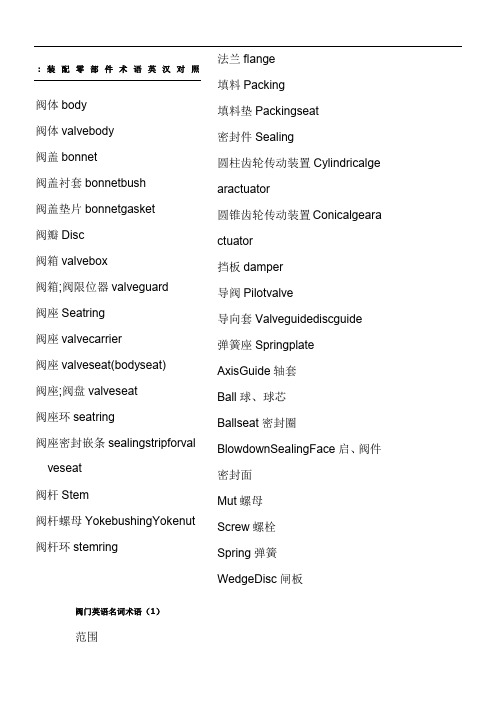
:装配零部件术语英汉对照阀体body阀体valvebody阀盖bonnet阀盖衬套bonnetbush阀盖垫片bonnetgasket阀瓣Disc阀箱valvebox阀箱;阀限位器valveguard阀座Seatring阀座valvecarrier阀座valveseat(bodyseat)阀座;阀盘valveseat阀座环seatring阀座密封嵌条sealingstripforval veseat阀杆Stem阀杆螺母YokebushingYokenut 阀杆环stemring 法兰flange填料Packing填料垫Packingseat密封件Sealing圆柱齿轮传动装置Cylindricalge aractuator圆锥齿轮传动装置Conicalgeara ctuator挡板damper导阀Pilotvalve导向套Valveguidediscguide弹簧座SpringplateAxisGuide轴套Ball球、球芯Ballseat密封圈BlowdownSealingFace启、阀件密封面Mut螺母Screw螺栓Spring弹簧WedgeDisc闸板阀门英语名词术语(1)范围??本标准适用于工业管道(或机器、设备)的通用阀门。
??阀门分类??阀门valve??用来控制管道内介质流动的,具有可动机构的机械产品的总体。
??闸阀gatevalve,slidevalve??启闭件(闸板)由阀杆带动,沿阀座(密封面)作升降运动的阀门。
??截止阀globevalve,stopvalve??启闭式(阀瓣)由阀杆带动,沿阀座(密封面)轴线作升降运动的阀门??节流阀throttlevalve??通过启闭件(阀瓣)改变通路截面积,以调节流量、压力的阀门。
??球阀ballvalve??启闭式(球体)绕垂直于通路的曲线旋转的阀门。
??蝶阀butterflyvalve??启闭式(蝶板)绕固定轴旋转的阀门。
??隔膜阀diaphragmvalve??启闭式(隔膜)由阀杆带动,沿阀杆轴线作升降运动,并将动作机构与介质隔开的阀门。
EHA 电液作动器介绍

有产品的元件,都是非常简单的事情。
9
Micro-Hydraulic System
Integrated EHA
Seals 密封
Hydraulic Motor 液压马达
Motor type Gear Motor, Cycloid Motor 马达类型 齿轮马达、摆线马达
Stroke length Max. 2000mm, Depending on Torque
-20°C to +150°C
基于磷酸酯的难燃液,及适应
氟橡胶、聚四氟乙烯
于高温环境下的液压油。
10 Micro-Hydraulic System
Integrated EHA
Performance 性能
Actuator 执行器
Cylinder 液压缸
Bore sizes 缸径规格
From 20mm to 125mm 从20mm至125mm
Medical/patient handling 医疗/病人设备
• Stretchers & beds 担架和医疗床 • Ambulance cots 救护床 • Wheelchair access ramps 轮椅进入坡道 • Kneeling handicap vans 下跪式残疾车
Micro-Hydraulic System
Integrated EHA
Features and Benefits 功能和优点
1. Motor 电机 2. Pump 泵 3. Cylinder 缸 4. sensor传感器 5. Mounting type 安装方式6. Valves assembly阀组 7. Reservoir 油箱
飞行模拟机缩写大全

ABCU〔Alternative Breaking Control Unit〕备用刹车掌握组件ACARS〔Aircraft Communication Addressing and Report System〕飞机通信寻址与报告系统ACCU〔Accumulator〕蓄压器AIB〔Audio Interface Box〕音频接口盒ALARM ACKNOWLEDGED 警告确认按钮ADF〔Automatic Direction Finder〕自动方位搜寻器/自动定向机ADIRS〔Air Data Inertial Reference System〕大气数据惯性基准系统ADIRU〔Air Data Inertial Reference Unit〕大气数据惯性基准组件ADR〔Air Data Reference〕大气数据基准AFDS〔Autopilot Flight Director System〕自动驾驶飞行指引系统AFM〔Aircraft Flight Manual〕飞机飞行手册AMPS〔Ampere,AMPS 是复数形式〕安培〔电流单位〕A/P〔Automatic Pilot〕自动驾驶APL〔Airplane〕飞机APO〔Auto Power Off Device〕自动电源关断装置APU〔Auxiliary Power Unit〕关心动力装置ARPT〔Airport〕机场Ashtray /ˈæʃˌtre/烟灰缸ASIC〔Application Specific Integrated Circuit〕专用集成电路A/SKID&N/W STRG 防滞与前轮转弯掌握电门A/T〔Auto Throttle〕自动油门ATD〔ActualTime Departure〕实际离港时间A/W〔AccessWay〕通道AWG〔American Wire Gauge〕美国线规BARO〔Barometric〕大气压力BAT DISCHARGE电瓶放电BC〔Battery Chargers〕电瓶充电器BFEBSCU〔Breaking and Swerve Control Unit〕刹车和转弯掌握组件Captain 机长〔Pilot In Command〕CAN〔Controller Area Network〕掌握器局域网络CB〔Contact Block〕接触块,接点排CB〔CircuitBreaker〕电路跳开关CCD〔Cursor Control Device〕光标掌握装置CDB〔Common Database〕公用数据库CDU〔Control Display Unit〕掌握显示组件CE〔Symbol for European Compliance〕CH〔Channel〕C/L〔Check List〕检查单CMB〔Control Monitor Board〕监视掌握板CPDSP〔Compact PCI Digital Signal Processor〕外设部件的数字信号处理器CPMONCPPDM〔〕CSV〔Comma Separated Values〕逗号分隔值〔文件格式〕CPICPS〔Cycles Per Second〕~次/秒〔频率单位〕CPSIO〔Compact PCI Sound & Audio Input / Output〕外设部件音频/音响输入/输出CPTMCTS〔Commercial Training Solutions〕Current Rating 额定电流CVR〔Cockpit Voice Recorder〕驾驶舱话音记录器C/W〔Control Wheel〕驾驶盘DB〔Daughter Board〕子板DBU〔Digital Buffer Unit〕数字式缓冲装置DECEL〔Decelerate〕减速DEU〔Display Electric Unit〕显示电子装置DFCS〔Digital Flight Control System〕数字式飞行操纵系统DiGIT〔Distributed Graphical Interface Tool〕-a Graphical User Interface (GUI) tool that providesa touch-screen orientated Human MachineInterface (HMI).DMC〔Datapath Micro Computer〕数据通道微处理器DMC〔Digital Motor Controllers〕数字式发动机掌握器DOF〔Degree Of Freedom〕自由度DOME WHITE 顶部白光DPS〔Distributed Power Supply〕分布式供电源Drawbridge 开合桥,活动吊桥DS〔Downstream〕下游DSP〔Display Select Panel〕显示选择面板D-sub〔D-subminiature[adj.超小型的,微型的]〕即VGADual Lock 联动拉手,双锁扣DVI〔Digital Visual Interface〕数字视频接口DU〔Display Unit〕显示组件ECAM〔Electronic Centralized Aircraft Monitoring〕电子集成飞机监控系统〔AIRBUS〕ECB〔Electronic Control Box〕电子掌握盒ECL〔Electric Control Loading〕EEPROM〔Electrically Erasable Programmable Read-Only Memory〕电可擦可编程只读存储器EFB〔Electronic Flight Bag〕电子飞行包EFIS〔Electronic Flight Instrument System〕电子飞行仪表系统EGT〔Exhaust Gas Temperature〕排气温度EDB〔Electronic Load Unit Dynamic Brake〕电子式负荷装置动态制动器EICAS〔Engine Indication and Crew Alerting System〕发动机指示机组警告系统〔Boeing〕EID〔Electronic Load Unit Identification〕电子式负荷装置识别ELAC〔Elevator Aileron Computer〕升降舵副翼计算机EMA〔Electro-Mechanical Actuators〕电动机械作动筒EMC〔Electro-Magnetic Compatibility〕电磁兼容性EMI〔Electro Magnetic Interference〕电磁干扰EMM〔Electro-Mechanical Motion〕电动机械运动EMO〔Emergency Motion Off〕紧急运动关断EMS〔Electro-Mechanical Susceptibility〕电磁敏感性EPO〔Emergency Power Off〕紧急电源关断回路EPR 〔Engine Pressure Ratio〕发动机压力比ETA〔Estimated Time of Arrival〕估量到达时间E/WD〔Engine/Warning Display〕发动机/警告显示FAIL〔Failed/Failure〕失效FBW〔Fly By Wire〕电传操纵FC〔Flight Compartment〕驾驶舱FCC〔Flight Control Computer〕飞行掌握计算机FCOM 〔Flight Crew Operation Manual〕飞行机组操作手册FCU 〔Flight Control Unit〕飞行掌握组件F/D〔Flight Director〕飞行指引仪FDAU〔Flight Data Acquisition Unit〕飞行数据采集组件FEA〔Finite Element Analysis〕有限元分析FFS〔Full Flight Simulator〕全动模拟机Feed Valve进给阀,进水阀,给气阀Flash Light=Torch 手电筒FLSCU〔Fuel Level S Control Unit〕燃油面探测掌握装置Fly-by-wire 电传操纵F/O〔First Officer〕副驾驶FOB〔Fuel Oil Board〕机载燃油量FPGA〔Field Programmable Gate Array〕现场可编程门阵列FPV〔Flight Path Vector〕飞行航迹向量FREQ〔Frequent〕频率FTA〔Fault Tree Analysis〕故障树分析Full Face Mask 全罩式面罩GPIM〔General Purpose Interface Module〕通用接口模块GPM〔Gallon Per Minute〕~加仑/分钟〔流量单位〕GPS 〔Global Positioning System〕〔全球定位系统〕GPU 〔Ground Power Unit〕地面电源装置GPWS〔Ground Proximity Warning System〕地面迫近警告系统GUI〔Graphical User Interface〕图形用户界面Hand Microphone 手持话筒Handset Stowage 手持听筒Hat Holder 帽夹Hat Stowage 帽子存放处Headset〔尤指带麦克风的〕头戴式受话器,耳机HDAC〔Hydraulic Accumulator〕HOST〔Host Computer〕HPU〔Hydraulic Power Unit〕液压工作站Hz〔Hertz〕赫兹IBUTTON〔Information Button〕信息纽扣IDG〔Integral Drive Generator〕整体驱动发电机IDLE 慢车IFB〔Interface Board〕接口板IG〔Image Generator〕图像发生器IGBT〔Insulated Gate Bipolar Transistor〕绝缘栅双极晶体管IN/SEC〔Inches Second〕英寸/秒IOM〔Input / Output Module〕IOS〔Instructor’s Operator〕S t教a t员i o操n纵台IPT〔Integrated Procedures Trainer〕综合程序训练器IR〔Inertial Reference〕惯性基准ITMS〔Integrated Terminal Management System〕终端综合治理系统JAA〔Joint Air Agency〕联合航空当局Jack Panel 插座面板Jet Pump 喷射泵Knots ~海里/小时〔~节〕KRST-复位继电器KSRA-安全继电器LBS 磅LE〔Leading Edge〕〔机翼〕前缘LED〔Light Emitting Diode〕发光二极管LGCIU〔Landing Gear Control and Interface Unit〕起落架掌握接口组件Line Maintenance 日常维护LPM〔Liter Per Minute〕~升/分钟〔流量单位〕LPS〔Lesson Plan Studio〕课程打算工作室LRU〔Line Replaceable Unit〕—An item that is replaced either on the simulator or if not possibleas a shop or bench procedure to an assembly 现场可更换部件LTK Pumps〔Left Tank Pumps〕左油箱燃油泵MCC〔Motion Control Card〕运动掌握卡MCL〔MotionControl Logic〕运动规律掌握MCL〔Motion andControl Loading〕运动和操纵负荷MCDU〔Multipurpose Control & Display Unit〕多功能掌握显示组件MDA〔Motion Drive Algorithm〕运动驱动算法Medical Kit 医药用品MENGD〔Motion Engaged Signal〕运动信号MPIC〔Multi Purpose Interface Card〕多功能接口卡MSB〔Most Significant Bit〕最高有效位MTRS〔备用工作电门,以米和英尺显示高度和MCP 选择高度〕计量电门N/A〔Not Applicable〕不适用Navigation Light 航行灯NDB〔Non Direction Beacon〕无方向信标台NDT〔Navigation Data Tool〕NSA〔Non Simulated Area〕OEM〔Original Equipment Manufacturer〕原始设备制造商PBE〔Protective Breathing Equipment〕防护呼吸面罩PCI〔Peripheral Component Interconnect〕外设部件互连标准PCM〔Power Conditioning Module〕功率调整模块PCU〔Power Control Unit〕动力掌握组件PDU〔Power Distribution Unit〕电力安排单元PEDALS 脚蹬PFC〔Power Factor Correction〕功率因数补偿PLUG-AND-PLAY即插即用Port Wing 左翼Portable OXY Bottle 手提式氧气瓶P/S〔Power Supply〕供电源PSI〔Pounds per Square Inch〕~磅/平方英尺〔压力单位〕〔1BAR=14.5PSI=0.1MPa〕PTC〔Positive Temperature Coefficient〕正温度系数QRH〔Quick Reference Handbook〕快速检查单QTG〔Qualification Test Guide〕品质测试指南RainRepellent Bottle 拨水剂瓶Restraint Kit 座椅安全带设备RTP〔Radio Turning Panel〕RIBBON CABLE 扁平电缆RJ〔Registered Jack〕注册的插座RLS〔Remote Light Sensor〕远距光传感器RM〔Relay Module〕继电器模块RMI〔Rotary Magnetic Indicator〕无线电磁指示器RMS〔Root Mean Square〕均方根R&R〔Removaland Replacement〕拆卸与更换RTH〔Return toHome〕RTP〔Radio Turning Panel〕RTX〔Real-time Extension〕实时系统扩展SAT〔Static Air Temperature〕静温SBC〔Single Board Computer〕单板计算机SD〔System Display〕系统显示Secondary Circuit Breakers 关心电路跳开关SERCOS(Serial real time Communication System)串行实时通信系统SERCOS(Serial real time Communication Specification)串行实时通信协议Signaling Kit 信号盒Smoke Hood 防烟面罩SOV〔Shut Off Valve〕关断活门STA (Scheduled Time Arrival) 打算到达时间Stowage〔船或飞机上〕存放物品处TAT〔Total Air Temperature〕机外温度=〔SAT+动温〕TAXI〔Taxiway〕滑行道TB〔Terminal Block〕接线端子TCAS〔Traffic Collision Avoidance System〕空中防撞系统TE〔Trailing Edge〕后缘TERR〔Terrain〕地形TFC〔Traffic〕交通Thermistor/θɜ:”mɪst / 热敏电阻UL〔Underwriters Laboratory〕美国一家进展安全认证的企业UNLK〔Unlock〕UPS〔Uninterruptible Power Supply〕不连续电源UTC〔Universal Time Coordinated〕国际协调时VAC〔Volts Alternating Current〕沟通电压VDC〔volts Direct Current〕直流电压VGA〔Video Graphics Array/Adapter〕视频图像阵列/适配器VOR〔VHF Omnidirectional Range〕甚高频全向信标WPT 〔Waypoint〕航路点WXR〔Weather Radar〕气象雷达X-Bleed 交输活门XPDR〔Transponder〕应答机YAWDAMPER偏航阻尼器。
压电叠堆执行器迟滞非线性建模与分析
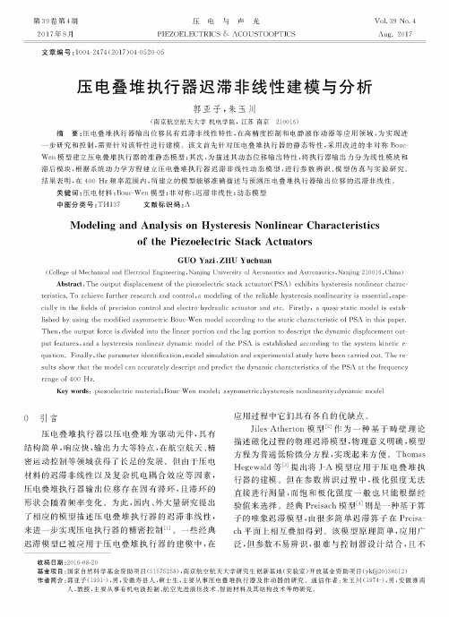
第39卷第4期2017年8月压电与声光PIEZOELECTRICS & 八COUSTOOPTICSVol. 39 No.4Aug.2017文章编号:1004-2474(2017)04-0520-05压电叠堆执行器迟滞非线性建模与分析郭亚子,朱玉川(南京航空航天大学机电学院,江苏南京210016)摘要:压电叠堆执行器输出位移具有迟滞非线性特性,在高精度控制和电静液作动器等应用领域,为实现进一步研究和控制,需要针对该特性进行建模。
该文首先针对压电叠堆执行器的静态特性,采用改进的非对称Bouc- W e n模型建立压电叠堆执行器的准静态模型;其次,为描述其动态位移输出特性,将执行器输出力分为线性模块和滞后模块,根据系统动力学方程建立压电叠堆执行器迟滞非线性动态模型,进行参数辨识、模型仿真与实验研究。
结果表明,在400 H z频率范围内,所建立的模型能够准确描述与预测压电叠堆执行器输出位移的迟滞非线性。
关键词:压电材料;Bouc-W en模型;非对称;迟滞非线性;动态模型中图分类号:T H137 文献标识码:八Modeling and Analysis on Hysteresis Nonlinear Characteristicsof the Piezoelectric Stack ActuatorsGUO Yazi,ZHU Yuchuan(College of Mechanical and Electrical Engineering»Nanjing University of Aeronautics and Astronautics»Nanjing 210016 »China) Abstract:T he output displacem ent of the piezoelectric stack actuator(PSA) exhibits hysteresis nonlinear characteristics. To achieve further research and control,a modeling of the reliable hysteresis nonlinearity is essential,especially in the fields of precision control and electro-hydraulic actuator and etc. Firstly, a quasi-static model is established by using the modified asym m etric Bouc-W en model according to the static characteristic of PSA in this paper. T hen, the output force is divided into the linear portion and the lag portion to descript the dynamic displacem ent output features,and a hysteresis nonlinear dynamic model of the PSA is established according to the system kinetic equation. F inally,the param eter identification,m odel sim ulation and experim ental study have been carried out. T he results show that the model can accurately descript and predict the dynamic characteristics of the PSA at the frequency range of 400 Hz.Key words:piezoelectric m aterial;Bouc-W en m odel; asym m etric;hysteresis nonlinearity;dynamic modelo引百压电叠堆执行器以压电叠堆为驱动元件,具有 结构简单,响应快,输出力大等特点,在航空航天、精 密运动控制等领域获得了长足的发展。
液化烃(球罐)根部防火阀国产化解决方案

液化烃(球罐)根部防火阀国产化解决方案作者:高丽华来源:《今日自动化》2021年第08期[摘要]中石化石家庄炼化分公司新区建设期间,首次遇到国家对液化烃(球罐)根部阀做防火要求,当时设计为进口阀门,费用高,采购周期长,不满足采购需求,为降低采购费用,缩短采购周期,达到液化烃(球罐)根部防火阀设计要求,依据设计技术参数,针对大口径阀门采用国产一体式电液执行机构及阀门,经过自动复位设计,使执行机构具有故障安全性能,并且执行机构采用进口防火罩保护,阀门经过整体防火设计达到了安全完整性等级要求。
当火灾发生时,阀门可以自动快速切断介质,保证罐区安全。
[关键词]罐根阀;球阀;防火罩;电液执行机构[中图分类号]TE65 [文献标志码]A [文章编号]2095–6487(2021)08–0–02[Abstract]During the construction of the new area of our company, we encountered the national fire protection requirements for the root valve of liquefied hydrocarbon (spherical tank) for the first time. At that time, it was designed as an imported valve. The cost was high and the procurement cycle was long. It did not meet the procurement requirements. In order to reduce procurement costs and shorten procurement Cycle, meet the design requirements of the fire damper at the root of liquefied hydrocarbon (spherical tank). Based on the design technical parameters, this article adopts domestic integrated electro-hydraulic actuators and valves for large-diameter valves. After automatic reset design, the actuators have fail-safe performance, and The actuator adopts imported fire protection cover, and the valve meets the requirements of safety integrity level through the overall fire protection design. When a fire occurs, the valve can automatically and quickly cut off the medium to ensure the safety of the tank area.[Keywords]tank root valve;ball valve;fire shield;electro-hydraulic actuator球罐作為一种特殊的压力容器,被广泛用于存储液化石油气、液化天然气、液态丙烯、液态丁烯、液氧、液氮等介质。
Q_KTZ002-2019电动液压执行器试验方法
Q 江苏今创自控科技有限公司企业标准Q/KTZ002-2019电动液压执行器的试验方法 Testing method for Electro-hydraulicactuators2019-10-10 发布 2019-10-14实施江苏今创自控科技有限公司发布目次1范围 (4)2规范性引用文件 (4)3术语与定义 (4)4试验方法 (5)4.1试验条件 (5)4.1.1一般大气条件 (5)4.1.2动力条件 (5)4.2试验的一般规定 (5)4.3试验方法 (6)4.3.1与准确度有关的试验 (6)4.3.2与影响量有关的试验 (7)4.3.3与安全性能相关的试验 (11)4.3.4其它性能项目的试验 (11)4.3.5功能检查 (15)5检验规则 (16)5.1型式试验 (16)5.2例行试验 (16)5.3检验项目 (16)前言为了规范电动液压执行器的生产和管理,保证电动液压执行器的质量,特制订本标准。
本标准主要依据GB/T 1.1-2009《标准化工作导则第1部分:标准的结构和编写》进行编制。
本标准由江苏今创自控科技有限公司提出。
本标准由江苏今创自控科技有限公司起草。
本标准主要起草人:张帅审核:刘进批准:杨维国本标准于2019年10月10日首次发布。
1范围本标准规定了电动液压执行器的型式试验、例行试验方法及判定依据。
本标准适用于各行程的电动液压执行器(以下简称执行器)。
2规范性引用文件下列文件中的条款通过本标准的引用而成为本标准的条款。
凡是注日期的引用文件,其随后所有的修改单(不包括勘误的内容)或修订版均不适用与本标准,仅所注日期的版本适用于本标准。
凡是不注日期的引用文件,其最新版本(包括所有的修改单)适用于本标准。
GB 4208 外壳防护等级(IP代码)(GB 4208-2008,IEC 60529:2001,IDT)GB 4793.1 测量、控制盒实验室用电气设备的安全要求第1部分:通用要求GB/T 15479 工业自动化仪表绝缘电阻绝缘强度技术要求和试验方法GB/T 16511 电气和电子测量设备随机文件(GB/T 16511-1996,idt IEC 61187:1993)GB/T 16842 外壳对人和设备的防护检验用试具(GB/T 16842-2008,IEC 61032:1997,IDT)GB/T 17626.2 电磁兼容试验和测量技术静电放电抗扰度试验GB/T 17626.3 电磁兼容试验和测量技术射频电磁场辐射抗扰度试验GB/T 17626.4 电磁兼容试验和测量技术电快速瞬变脉冲群抗扰度试验GB/T 17626.5 电磁兼容试验和测量技术浪涌(冲击)抗扰度试验GB/T17626.6 电磁兼容试验和测量技术射频场感应的传导骚扰抗扰度GB/T17626.8 电磁兼容试验和测量技术工频磁场抗扰度试验GB/T4824 工业、科学和医疗(ISM)射频设备骚扰特性限值和测量方法JB/T 9329 仪器仪表运输、运输储存基本环境条件及试验方法GB/T 17212 工业过程测量和控制术语和定义3术语与定义GB/T 17212确立的术语与定义适用于本标准。
- 1、下载文档前请自行甄别文档内容的完整性,平台不提供额外的编辑、内容补充、找答案等附加服务。
- 2、"仅部分预览"的文档,不可在线预览部分如存在完整性等问题,可反馈申请退款(可完整预览的文档不适用该条件!)。
- 3、如文档侵犯您的权益,请联系客服反馈,我们会尽快为您处理(人工客服工作时间:9:00-18:30)。
∗ JKU † Austrian
HOERBIGER Research Institute for Smart Actuators, Linz, Austria Center of Competence in Mechatronics (ACCM), Linz, Austria
978-1-4673-1301-8/12/$31.00 ©2012 IEEE 511
life cycle [1]. A brief literature review shows many different ways to calculate the temperature distribution of a machine. They can be classified in three main groups: The first possibility is the method of Finite Elements (FEM) [2]. It allows parameterized modeling but in general the effort to create and simulate the model is time consuming, especially if 3D models are used. On the other hand these models have the advantage to allow the coupling of thermal and electro-magnetical issues. The second group of models solve the thermal differential equations analytically. These analytical results directly show the dependency of the parameters and therefore give the maximum possible insight into the geometrical influences on the temperature distribution. Unfortunately the differential equations can be directly solved only for very simple geometries. This strongly limits the usability of such models. The third and biggest group is positioned between the previously described ones and uses an electrical network representation for modeling the thermal behavior. The challenge is here to define the parameters of the elements of the equivalent circuit (i.e. resistors, capacitors, ...). However the results for both transient and steady state analysis can easily be obtained. Now different kinds of models can be realized using electric networks which depict mathematically lumped parameter models because of their discretized spatially calculated properties. On the one hand there are geometrically distributed parameter models [3], [4] and on the other hand there are geometrically lumped descriptions [5], [6], [7], [8], [9]. Latter models outline a system by showing only parameters for summarized parts. For example to model an electrical motor parts like the stator, rotor, etc. are identified and represented by equivalent resistors and capacitors for each part. The major disadvantage of geometrically lumped models is that further assumptions have to be made because the system of equations is often under-determined. On the other hand an advantage is the use in combination with real time estimation of temperature for integration in feed-backward control strategies because of its fast speed [8]. Lumped parameter models with geometrically distributed elements are often found for calculation of thermal
Abstract—In highly exploited and integrated mechatronic systems the thermal design and management defines the maximum load case. The trend to move to higher power densities needs precise andห้องสมุดไป่ตู้reliable thermal models of electrical machines to determine the limits of new and thermally demanding use cases and/or gives design guidelines for future generations of the product. For the electro-hydraulic system investigated in this paper a mathematically lumped parameter model with geometrically distributed elements has been developed. The thermal properties of the elements are calculated with physical material properties according to their geometric sizes. This allows to implement a comfortable parameterized interface that facilitates an easy change of geometrical dimensions and material properties. Moreover sub-sections of the system can be grouped which allows modularized modeling - this possibility shows its strength when an electrical sub-system is combined with a hydraulic sub-system. Together with automated model generation the resulting SPICE model is well suited for parameterized optimization. The model applies to both transient and/or steady state temperature including the effects of heat radiation and air convection. Thus, fast and accurate calculation of the temperature distribution and heat flow is possible and has been validated by measurements on a test rig. Index Terms—electric network, electro-hydraulic actuator, geometrically distributed elements, lumped parameter model, thermal model.
I. I NTRODUCTION Along with advancing power density and optimization the temperature distribution in an electro-hydraulical system gains importance. However it is mainly not the overall thermal behavior of a system that limits the performance, but the temperature at specific points or in specific areas. These areas contain components or materials with a defined maximum operating temperature which limits the safe operational area of the system. In the demand to increase the operational area it is crucial to understand not only the thermal distribution but also the interconnections of the involved subsystems. The main focus rests here on the calculation of the temperature distribution in the electrical, mechanical or hydraulic sub-systems due to internal heat losses. Since the beginning of the developement of electrical machines it is recognized that an efficient cooling of a system/machine is absolutely necessary to maintain its