卡麦隆cameron压缩机cfa34说明书
EMAX 压缩器杆头压缩机产品说明书

EMAX Compressor Piston reciprocating Warranty StatementIMPORTANT!! You must register your compressor:To register your warranty and find theextended warranty options go to . Details and options for ourextended warranty will be provided online once you enter the required information.EMAX Compressor makes the following Warranty guarantee:•Standard Warranty: That each compressor unit is free from defects in material, workmanship, and parts for 1 year from the date of delivery. This Standard Warranty includes 1 year ofwarranty labor from an authorized technician. EMAX compressor is not responsible fordowntime during warranty service. If downtime is necessary, it is at the owner’s discretion,obligation, and expense, to have a redundant compressor. Parts shipped for warranty repairsshall only include ground freight charges for the first 90 days of the warranty period, thereafter owner is responsible for all freight charges of parts shipped for warranty. Any and all expresssh ipping charges of warranty parts would be at the owner’s expense. Standard technicalassistance is provided at no charge during and after the standard warranty period.•Honda Engine carry’s a 3 year Limited warranty under all warranty Tiers*Standard warranty has no obligation to maintain warranty status, warranty will expire one year from date of delivery. Please see available options below to extend your warranty.•Extended Warranty: EMAX compressor will extend your standard 1-year warranty to full 5 years when you opt to register for the extended warranty plan that includes using our SMART OIL™ and follow ing all routine maintenance set forth. Parts shipped for warranty repairs shall only include ground freight charges for the first 90 days of the warranty period, thereafterowner is responsible for all freight charges of parts shipped for warranty. Any and all expressshipping charges of warranty parts would be at the owner’s expense. Standard technicalassistance is provided at no charge during and after the standard warranty period.Required maintenance Schedule to maintain warranty status➢All units are shipped with break-in oil and must be changed no less than 70 hours to insure gasket seating.➢After the 70 hours of break-in you must change the oil➢Thereafter Oil Should be changed every 6 months or 1000 hours whichever occurs first.➢Always maintain proper oil level in unit. If the unit runs out of oil due to neglect the warranty will be void.➢Use only EMAX approved oils in your compressor, or your warranty is void.**Extended Limited Lifetime Pump Warranty With participation in our SMART OIL™ extended auto ship program EMAX compressor will extend your warranty plan to **Limited LifetimeWarranty on the pressure lubricated pump. All other non-wear and tear components to 10years. SMART OIL™ not only extends the life of your compressor pump, it also can reduceoperating noise levels and can create further energy savings. Warranty repair parts under theLimited Lifetime warranty will not include any shipping charges beyond the Standard Warranty, therefore owner is responsible for all freight charges for warranty parts. This plan includes our advanced technical air support. Smart Tech Support provides you with the highest level oftechnical support. Smart Tech support is an interactive support team available to you at yourfingertips by just downloading a free app. The app provides free remote meetings, interactivetouch display, real live personal to assist.Limited Lifetime Warranty is not prorated and has no hour limits.**Limited Lifetime Warranty, non-prorated, no hour limits. In the case the product has been discontinued atany point the Limited lifetime Pump warranty will last five years past the discontinued date. Warrantor hasdiscretion to substitute parts with current model for the five-year duration*In order to maintain Limited Lifetime Warranty status, the owner must adhere to and purchase from EMAX Compressor the required maintenance items as scheduled below utilizing our Smart Whisper Blue Auto Ship program:Required maintenance Schedule to maintain warranty status➢All units are shipped with break-in oil and must be changed no less than 70 hours to insure gasket seating.➢After the 70 hours of break-in you must change the oil➢Thereafter Oil Should be changed every 6 months or 1000 hours whichever occurs first using only our Smart Whisper Blue Oil➢Always maintain proper oil level in unit. If the unit runs out of oil due to neglect the warranty will be void.➢Use only Smart Whisper Blue Oil and filters purchased from Emax Compressor in yourcompressor, or your warranty will be voided.➢Must be an active member of EMAX Compressor auto ship program•Warranty Shall not apply and Emax Compressor shall not be responsible nor liable for: ➢Routine service such as oil changes, filter replacements, gasket tightening to correct oil seepage or drive belt tightening and valve cleaning and are not covered under warranty.➢Consequential damages such as but not limited to cost of loss of business, product damage, or down time➢Acts of nature, over abuse, malicious destruction, improper maintenance, undersized equipment➢In the case the product has been discontinued at any point the *Limited lifetime warranty will last five years past the discontinue date. EMAX Compressor has discretion to substitute partswith current model for the five-year duration.➢Deviation from operating instructions or specifications➢Labor charges for repairs or maintenance made by person(s) other than an authorized, approved service technician or any labor after the 1-year Standard Warranty expires.➢Normal wear and tear parts included but not limited to valves (intake/suction, check, blowdown, thermo, pop off, unloader), and ball valves. Belts, shaft seals, load/unloader solenoids, sensors(temperature or pressure), Electrical contractors and relays, and any parts with a routinemaintenance scheduleWarranty shall be voided under the following conditions: Exposing electrical components to rain or water, or installing the unit in a hostile environment such as acid vapors or any caustic or abrasive matter that may be ingested into the pump, or installing the unit in an enclosed area where lack of cooling ventilation is present, such as in boiler or equipment rooms where the ambient air exceeds 100F.Further exclusions include failure to fully and completely follow the guidelines set forth in the manual. Of specific note is environments where fine dust is common, such as granite, marble or concrete plants, the compressor MUST be installed in a separate area with its own dedicated ventilation. FAILURE TO PROVIDE THIS DUST FREE OPERATING AREA VOIDS THE WARRANTY.Parts used for warranty purposes must be supplied by EMAX Compressor. Warranty work should be performed by an EMAX Compressor approved Technician. If any maintenance (other than routine maintenance) is performed by a non-approved Technician, written pre-approval must be obtained from EMAX Compressor, to prevent voiding this warranty. Failure to fully comply with this warranty and fully comply with the manual instructions will void this warranty.Warranties are non-transferableThe oil purchase and maintenance program are effective as of Nov. 2019。
天然气压缩机机操作规范
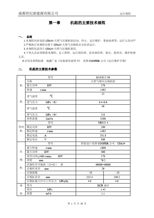
第一章机组的主要技术规范一、总则1.本规程内容包括CFA34天然气压缩机的启动、停止、运行维护、事故处理等,运行人员应严2.严格执行本规程以便于CFA34天然气压缩机安全经济运行。
3.本规程仅适用于CFA34天然气压缩机使用。
4.下列人员必须熟悉本规程:总工程师、运行部经理、技术部经理、值长、值班员、维护检修人员。
5.引用及参照标准成撬厂家《安装使用说明书》美国COOPER公司《运行维护手册》二、机组的主要技术参数三、机组设计运行参数表四、机组主要部位装配要求五、机组用润滑油规定六、 盘面布置图七、电气单线图八、CFA34天然气压缩机结构及系统介绍1.主机部分主要包括驱动电机、机身部分和压缩部分。
CFA34压缩机分为四个压缩缸、两级压缩,四个压缩缸呈水平相反布置,驱动电机与曲轴箱内曲轴相连传递给压缩缸做功。
驱动电机、压缩机以及部分配套设施安装在机座上,进排气分离过滤等压力容器安装在机座上,天然气冷却器安装在机座上,构成一台整体式撬装机组。
2、润滑油系统润滑油系统有预润滑油泵、主油泵、油过滤器、油冷却器、注油器、分油器、油流指示器、油位开关等组成;预润滑油泵由电机驱动、主油泵由压缩机驱动。
润滑油系统主要为活塞、十字头等提供润滑。
3、进排气系统压缩机进排气有汽水分离器、近期缓冲罐、天然气冷却器,排气装有分离过滤分离器、天然气冷却器等。
4、压缩机仪表控制系统压缩机仪表控制系统用来监测流程参数、超限保护停机。
主要有监测天然气、润滑油、冷却水等介质压力、温度的压力变送器、热电阻,监测分离器液位的液位开关,监测机组振动的振动开关,监测机组润滑状况的无油流指示器(开关),监测曲轴箱油位的油位开关。
第二章操作规范一、系统送电1.初次送电前的检查1.1所有安装或检修工作已完成。
1.2检查所有线路已接完,且接线正确。
1.3检查所有送电回路绝缘电阻值和相间电阻,绝缘电阻值应符合要求(控制回路绝缘电阻应≥0.5MΩ,电源回路绝缘电阻应≥1MΩ),相间应无短路。
McMillan 空气压缩机用户指南说明书

Operating Manual
Product Catalogue
Quality Costs Less
“Celebrating 60 Years”
sales
.au
Identifying the Part Bare Pump - Vertical Twin Cylinder Schematic of Bare Pumps Bare Pump - Cast Iron 2 & 3 cylinder Schematic of Bare Pump Schematic of Built up Compressor
AlloAy lloy (2-s(2ta-gstea)ge) 25nm25nm 55nm5nm 55nm55nm 95nm95nm
7.4 Part Names – Cast Iron Compressor Pump
1 Cylinder Head 2 Inlet Filter Assembly 3 Valve Plate Gasket Set (3 gaskets) 4 Reed Valve 5 Valve Plate Assembly, including Gaskets 6 Cylinder 7 Ring Set 8 Piston/Ring Set 9 Oil Filler Plug & Washer 10 Oil Sight Glass & Washer 11 Oil Seal 12 Crankcase Breather 13 Flywheel 14 Flywheel Bolt & Washer
* Subject to motor manufacturers assesment and warranty. Contact McMillan Air Compressors. ** Covered by Honda and Yanmar agents. Contact your nearest dealer.
亚特兰蒂斯科普机械工业有限公司CR铜铁杠式压缩机系列说明书
A complete and tailored range of premium compressors at affordable pricesThe CR Cast Iron Piston Compressor SeriesNewly designed, lasting reliabilityMore dependable than ever with tailored options for all contractor, professional and industrial applications, Atlas Copco is pleased to introduce the newly designed CR cast iron piston compressor series. The CR range delivers a champion combination of outstanding reliability matched with robust performance, even in the most demanding conditions for a dependable piston you can count on.Capitalizing on heavy-duty cast iron construction and a combination of computer-aided design with controlledmachining processes, the new CR single stage and two-stage compressors deliver up to 175 psig with 24/7 reliability. We back this up with our bumper to bumper warranty packages, and have options for a 5 year extended warranty, depending on the model chosen.Count on Atlas Copco’s cast iron piston technology to drive your production reliably and support your application demand. We can meet your exact requirements with a broad piston compressor line, whether you work in a small workshop or on a large onsite project. A range of series with available options:Made in USACR Cast Iron Piston Air CompressorA 60 second guide to the piston that sets the bar high•Auto drain •After cooler•Low oil level switch •TEFC motorHeavy-DutyCast Iron constructionEnsures durability and reliability for the most demanding applications .ReliabilityEngineered using the most state-of-the-art manufacturing techniques for a product of design excellence. The compressed air you need to keep your operations running efficiently with maximum uptime.TailoredCustom ize your piston to fit your needs. Options available include:•NEMA4 control panel •Pressure lubricated pump •Simplex and duplex con gurationsEasy maintenanceEvery component is easily accessible allowing minimum downtime and requires only limited maintenance.The Contractor Series provides affordable compressed air in a small, lightweight package. The low-profile cast iron design, semi-pneumatic wheel, heavy gauge wire belt guard and rugged pump design provide the ideal solution for small, portable applications.Features and Benefits:•Standard 2-year b umper to b umper w arranty –No start-up kit required •Single stage units–Electric or gas powered•Fully enclosed belt guard and ASME safety valves •Pilot valve control on gas drive units to reduce engine s peed on low demand Technical Specifications*Voltage available from 115-230The CR Contractor SeriesA premium compressor at the lowest capital cost for point of use applications.2-5.5HP/135 psiThe CR Professional SeriesA reliable electric compressor for rugged, stationary use.5-20HP/135-175 psiThe Professional Series provides high pressure at the lowest cost in a small, lightweight package. The balanced counter weighed crankshaft and cast iron design provide smooth, easy operation with a range of unit options supplying an ideal solution for demanding applications.Features and Benefits:•1 year bumper to bumper with 5 year extended warranty on the pump*–*With purchase of minor and major maintenance kits •Duplex, Simplex or Base MountedTechnical SpecificationsCR Professional Series - Standard*Voltages available from 200-575 voltCR Professional Series - Standard and Packaged TEFC motor upgrade/NEMA4 control panelCR Professional Series - Packaged Duplex** - Single phase units stop at 7.5HP•Two-stage–Two stage best for high demands needing up to 175 psi.•Oversized oil reservoir for low oil temperatures,industrial class bearings and one-piece aluminum head for heat dissipation providing longevity.•Low m aintenance with 2-piece connecting rods and oil pressure gauge.•High efficiency intercooler with stainless steel valvedesign for highest volumetric efficiency.CR Industrial Series - Standard and TEFC motor and NEMA4 controller upgradeCR Industrial Series - Duplex TEFC motor and NEMA4 controller upgradeDuplex units offer twin motors and twin pumps for additional output and redundancy.The CR Industrial SeriesThe most reliable piston air compressor customizable to you.5-20HP/135-175 psiThe Industrial Series provides high pressure at low cost in a newly designed, cast iron package. The balanced counter weighed crankshaft provide a smooth, easy operation with a range of unit options supplying an ideal solution for the most robust applications. Features and Benefits:•1 year bumper to bumper with 5 year extended warranty on the pump*–*With purchase of minor and major maintenance kits •Duplex, Simplex or Base Mounted•Two-stage–Two stage best for high demands needing up to 175 psi•Oversized oil reservoir for low oil temperatures, industrial class bearings and one-piece aluminum head for heat dissipation providing longevity•Low Maintenance with 2-piece connecting rods and oil pressure gauge•High efficiency intercooler with stainless steel valve design for highest volumetric efficiency Technical SpecificationsCR Industrial SeriesThe CR Series piston compressor is a cast-iron, splash lubricated, 2 stage, 175psi product. All models are equipped with magnetic starter as standard. The industrial series comes equipped with an electric drain, belt guard aftercooler, and low oil level switch on all models. The 10 and 15HP models also come equipped with head unloaders.Buyers GuideLooking to customize your unit?Looking to complete your package?Optional add-ons•Protect your tools and end-products, investments and processes•Meet requirements for cleaner, dryer air •Reduce your service and maintenance costsIn-line Filters: General purpose, high efficiency and odor removal line filters to meet high quality air needs.Dryers: Avoid condensation and chance of corrosion by removing water from your compressed air.AIRnet Aluminum or Stainless Steel Piping: Easy to install, modular piping system for air and inert gases.E N © A t l a s C o p c o A B , S t o c k h o l m , S w e d e n . P r o d u c t i o n : A t l a s C o p c o B r a n d S t u d i o . P r i n t : B r a n dF a c t o r y , N o 2019Atlas Copco Compressors300 Technology Center Way Ste 550 Rock Hill, South Carolina 29730。
Worthington-Creyssensac VCI07 变速压缩机用户手册说明书

User’s manual ENVCI07For variable speed compressors62 205 930 11 ed00 Applicable as of Version 1209/04Worthington-CreyssensacPage 262 205 930 11Table of contains1 - GENERAL INFORMATION ..........................................................................................................................3 2- USER INTERFACE ......................................................................................................................................3 2.1 D ISPLAYS ..................................................................................................................................................3 2.2 P USH BUTTONS ..........................................................................................................................................4 2.3 LED’S .......................................................................................................................................................4 3- MENUS AND FUNCTIONS ..........................................................................................................................4 3.1 M ENU CODE ENTRY / PARAMETER MODIFICATION .........................................................................................4 3.1.1 Entering menus................................................................................................................................4 3.1.2 Parameter modification....................................................................................................................5 3.2 M ENU STRUCTURE – QUICK REFERENCE .....................................................................................................6 3.3 M ENUS AND CHANGEABLE FEATURES ..........................................................................................................7 3.3.1 Status menu.....................................................................................................................................7 3.3.2 Error log menu..................................................................................................................................7 3.3.3 Maintenance interval menu..............................................................................................................7 3.3.4 Basic settings menu.........................................................................................................................8 3.3.5 Machine configuration......................................................................................................................9 3.3.6 Regulating settings...........................................................................................................................9 3.4 M ICRO POWER INTERRUPTIONS ................................................................................................................10 4 - CONTRAST ................................................................................................................................................11 5 - MAINTENANCE .........................................................................................................................................11 6- START UP AND OPTIMISING FINAL MACHINE ADJUSTMENTS (11)7 - MAIN OCCURRENCES .............................................................................................................................12 8 - DRYER MANAGEMENT ............................................................................................................................13 9 - SPECIFIC VARIABLE SPEED MOTOR . (13)Worthington-Creyssensac 09/0462 205 930 11Page 31 - General informationThe VCI07 controller has been developed for the control of medium to large size variable speed compressors, integrating “Variable Speed”.The VCI07 has a metal housing and can be mounted inside or outside the electrical cabinet of the compressor.Two 3-digit LCD displays and an alphanumeric display with 2 lines of 16 characters permanently show the behaviour of the compressor.We devoted special attention to the development of a simple user interface.2 - User interfaceThe VCI07 controller is equipped with three bottom-view-side-lighted displays, 8 push buttons and 4 LEDS.StartStop Display Reset2.1 DisplaysThe VCI07 is equipped with 3-bottom view - side lighted displays. Each display is dedicated for a specific purpose:The following messages can be displayed:Message Meaning3 digit seven segment (left display) e.g. 6.8- - -• Current pressure is constantly beingdisplayed• Indicating a pressure sensor error3 digit seven segment (right display) e.g. 86- - -• Current temperature is being constantlydisplayed• Indicating a pressure sensor error Alpha numeric 2 lines 16 character e.g. emergency stop e.g. standbye.g. oil service Error indications Status indications Service timersTable 109/04Worthington-CreyssensacPage 462 205 930 112.2 Push buttonsThe VCI07 is equipped with 8 tactile push buttons. In the standard software, each push button has its own specific function.Arrow up Select previous menu item Arrow down Select next menu item Minus Exit current menu (back to previous) Plus Entering the selected menu Enter Modifying / confirming variable settings Green rectangular Starting the compressor locally Red rectangular Stopping the compressor locally Reset Return to the basic menu orReset the controller whenever an alarm/warning occurred.Table 22.3 LED’sThe VCI07 is equipped with 4 LEDS. Each LED has its own specific function.BAR The pressure unit is set at BAR (see Table 7 on page 9) PSI The pressure unit is set at PSI (see Table 7 on page 9)°CThe temperature unit is set at Celsius (see Table 7 on page 9) °F The temperature unit is set at Fahrenheit (see Table 7 on page 9)Table 33 - Menus and functions3.1 Menu code entry / parameter modificationThis paragraph explains how to select a menu and how to scroll through the different parameters.3.1.1 Entering menusand/or returning to the basic menuWorthington-Creyssensac 09/0462 205 930 11Page 5How the different menus and sub-menus can be entered, is shown below:3.1.2 Parameter modificationa) Parameter modification without password protection•Within the entered menu, select the parameter to be changed by scrolling through the menu with the up and down arrow-button (step 1)• Push the enter-button and the parameter value will start blinking (step 2) • Change the blinking value with the “+” or “-“ button (step 3) • Confirm with the enter-button (step 4)09/04Worthington-CreyssensacPage 662 205 930 113.2 Menu structure – quick referenceCurrent time & date set-up Date 1+time+pressure 1 Date 1+time+pressure 2 Date 1+time+pressure 3 Date 1+time+pressure 4 etc. ( up to 32 )Note: Dr. alarm and Dryer Start are visible if the drier option is enabled in the factory or in the SAV menu.Worthington-Creyssensac 09/0462 205 930 11Page 73.3 Menus and changeable features 3.3.1 Status menuThe status menu can be considered as the default menu. It is shown at start-up of the controller and the VCI07 will revert to this menu after one minute when the keyboard activity stops while displaying a different menu. The following messages are displayed :• Machine status (e.g. standby, blowing down, onload, offload, etc.) • Time and day• Errors - active faults are blinking (e.g. air. Temp ----, Oil filt P warn, etc.)3.3.2 Error log menuThe VCI07 saves the 10 most recent occurred faults. By using the up and down arrow-button all the messages can de displayed. Below an example is given:Fault log nr. 1 High pressure fault Occurred fault number 1 is being displayed Fault log nr. 2 Emergency stop Occurred fault number 2 is being displayed Fault log nr. 3 Air filter P warning Occurred fault number 3 is being displayed Fault log nr. 4 Temperature probe fault Occurred fault number 4 is being displayed (See Table 1 on page 3) Etc.Table 4After a fault has been selected and the enter-button is pushed continuously, the date and time is displayed when the fault occurred.3.3.3 Maintenance interval menuIn the timer menu the following timers can be checked:Running hours Total running hours is being displayed Loaded hours Total loaded hours is being displayed Air filter time Remaining hours to air filter service is being displayed Oil filter time Remaining hours to oil filter service is being displayed Oil separator time Remaining hours to oil separator service is being displayed Oil change time Remaining hours to oil change is being displayed Lubrication Motor lubricationTable 5Note: Setting and resetting the displayed values can be done in the service setting menu.09/04Worthington-CreyssensacPage 862 205 930 113.3.4 Basic settings menuOffload PFrom this level the machine starts working offload (for max. value see also factory settings). After a timing(“slow down time”), the compressor stops except the pressure has reached the pressure load level.8 6 P.max On Load P Pressure target in Variable Speed Regulation 6.6bar P. minOffload P.P.scheduleEnabling or disabling the pressure schedule OFF OFFON Press. schedule The current time can be set as well as the configuration of the pressure schedule throughout theweek (see 3.3.4.1 below)Drainspit time Opening time of the drain to release the moisture of the after cooling process2sec 1sec20secDrain dwell time Opening interval of the drain30sec 10sec120sec Dr. alarmDryer high temperature alert threshold 0 °C 5 °C30 °C Dryer start temporization of drier starting before the compressor= time necessary to produce dry air. 0 015minTable 63.3.4.1 Pressure scheduleThe pressure time menu is used for programming over an entire week of up to 32 different pressure settings (e.g.: [REF] onload P. or 7 bar pressure required), associated with specific times. To modify the parameters in this menu, also see settings: pressure time Chap. (3.2).06Jun Fri 10 :291999Mon 06 :307.0BARMon 17 :30[OFF]Mon 19 :00[OFF]Required pressure [REF] = Onload pressureWorthington-Creyssensac 09/0462 205 930 11Page 93.3.5 Machine configurationIn the machine configuration menu, the following application specific parameters can be set:or possible values Auto restart Automatic restart of the machine after a power failure in case when the machine was running before the power failure.ARR ARR MARStart ctrl Select between local ON/OFF (on VCI07 box) or remote ON/OFF via the digital input 3.ON/OFF check can also be made via the RS 485 link For example with LeadairLOC LOC, EXT, 485Press. ctrl Selection between (no load / load) operation locally or via the RS 485 link (with Leadair)Remark: The DI 06 digital input has priority over this check function.DI 06 is the low-pressure switch input.Placing a relay in series with this pressure switch makes it possible to remotely control the (no load /load) operation.LOC LOC 485Machine number Address of the controller in an RS485 network 1 1 254 P unit Selection of the pressure unit BAR BAR PSI T unit Selection of the temperature unit °C °C °F Power unit Defines and activates instantaneous power display % - - - % Language Selection of the language in which the messages are displayed.EnglishMin temp Minimum oil temperature below which the machine does not start.2 °C -10 °C +10 °CRelay 6 It defines R 06 output as: Alarm and fault reportingR 06 changes state in the event of a machine alarm Machine safety or maintenance counters to 0 ….. - or in the event of a faultthe machine stops due to a safety problem - Fault report (only)Machine state: Output activated if the machine is operating (stand by) or if the motor is running Alarm Alarm / Error / StateTable 7Important note:It is always possible to stop the machine locally when remote start / stop function is enabled.3.3.6 Regulating settingsWhile the compressor is running loaded, a variable output signal is being generated by the PWM output. This signal is based on a PI control algorithm and can be used to drive an actuator (e.g. a proportional valve or a frequency inverter). The pressure regulation algorithm will control the actuator in order to maintain the load pressure at all time. If the actuator can not sufficiently cut back, the compressor will rise until it reaches the unload pressure. The compressor will then unload and the PI pressure control algorithm is disabled. As the pressure goes down and reaches the load level again, the compressor loads again and the PI control will take over. (see Table 6, Chap. 3.3.4)09/04Worthington-CreyssensacPage 1062 205 930 11ATTENTION :Do not adjust correctors P and I. They undergo in-factory configuration for compatibility with more than 95% of installations. During the setup, the installer checks the settings. If in doubt contact our after-sales service.Min. value It reflects the minimum output level of the control algorithm atwhich can be cut back. Below this value, the compressor will beput offload. The minimum value is expressed in %.0% 0% 100% P factor This proportional control factor determines how much thecontrol will react to differences between actual and targetpressure.40% 0% 100% I factor This integral control factor determines the “weight” of theintegral on the control action.10% 0% 100%Model Maximum frequency management model. Setting dependent uponmachine type (see VCI07 settings instructions)Unload Fr. The frequency at which the machine turns in no load operation 20Hz 0Hz 200Hz Max. Freq. Maximum frequency of variator. Setting dependent uponmachine type (see VCI07 settings instructions)Min Freq. Motor-compressor minimum frequency, set into the variable speed drive. This parameter is useful for displaying the instantaneous power10Hz 0Hz 200HzMax. Power Maximum power of machine. Setting dependent upon machine type (see VCI07settings instructions)Onload loss Defined for instantaneous power calculation 0 16 Safety fac.= Safety factor and proportional correction. Setting dependent upon machine type (see VCI07settings instructions)Ventil Stop. Ventilator stop.OFF OFF ONT Vent. STOP Time between shaft stop and ventilator stop = tempo at which the ventilator continues to turn after shaft stop.This safety feature prevents the oil temperature from rising after the machine has stopped.60 0 600Fan sp. entr Activates the ventilation speed variation: used to control the oiltemperature OFF ON OFFTH reg. Visible when ‘Var ventil ‘ is active, this parameter is the oiltemperature setpoint: it is the desired oil temperature 80 °C 70 °C 100 °CTable 83.4 Micro power interruptionsThe VCI07 is standard equipped with a micro power interruption detection of 40ms function. Every zero passage of the 24VAC main is detected. When 2 consecutive cycles or a power failure of 40ms is detected, the controller will automatically stop the machine. At the same time, all relays are released and 3 horizontal dashes are displayed on the LED display. By stopping the machine during a micro power interruption, sparks on the relay contacts are avoided which will extend the relay lifetime.4 - ContrastThe only possible adjustment is the visual angle of the alphanumeric display. In the factory this angle is already adjusted to its best position. When another angle is wanted it can be changed by removing the black cap at the bottom of the unit. Just behind the aperture a 270 degrees potentiometer is located. Use a screwdriver with a 25mm blade or less to make the adjustment. Do not forget to replace the black cap.5 - MaintenanceThe VCI07 does not need maintenance. When the front panel is dirty, it can be cleaned with a soft cloth drenched in soap water or methanol.6 - Start up and optimising final machine adjustmentsThe machine undergoes in-factory configuration in order to limit the need for adjustments during installation. Therefore, only the pressure thresholds need to be set :- “OnLoad P” = desired regulation pressure (in vari-speed)In order to conserve energy to the maximum, it is advised to lower the regulation pressure to thelowest possible level ( so as to optimize power)- “Offload P” = Delayed stop pressure of the machineFor energy consumption that is less than the minimum capacity , it is advised to set it at + 0,5 barabove the “P load”.In certain rare cases, it may prove useful to adjust the regulation settings (see chapter 7, main operational occurrences).7 -Main occurrencesOccurrences Solutions1. THE MACHINE STOPS AND STARTS AGAIN BUTONLY FOR A SHORT TIME Increase unloading time (for +5 to +20 s) so that the motor doesn’t stop so often (the compressor runs for longer before stopping). If this delay is insufficient, increase the “unloading time” and the minimum unloading time by the same amount (for example : +30s)2. THE MACHINE STOPS, DISPLAYING THE MESSAGE”MOTOR ERROR” Check that there is no mechanical blockage of the motor. See variator instructions : the fault comes from the variator. Identify the fault.Ne pas réinitialiser la machine sans chercher la source du problème.3. THE OIL TEMPERATURE IS TOO HIGH (THEMACHINE STOPS OR AN ALERT IS GIVEN) Lower the pressure to the min. level that the client will need. Decrease the “dry fact” setting by 2 to 10%In the event of failure, proceed more progressively : by consecutive steps of 1 to 2%, testing each time the rise in machine temperature.In this way, machine cooling is steady and total absorbed power is reduced (as is the case with the capacity)4. THERE ARE LARGE FLUCTUATIONS OF PRESSURE(MORE THAN 0,2 BARS) FOR FLOWS IN BETWEEN THE MAXIMUM AND MINIMUM CAPACITYI. Read the variator frequency (see variator instructions) Check that it is higher than the minimum frequency (the capacity is thus higher than the minimum capacity). If this is the case, reduce the integral factor (I factor) so as to reduce fluctuations.Attention : reducing it too much will slow the rise in pressure.5. THE PRESSURE DOES NOT RISE QUICKLYIncrease the P factor.6. THE MACHINE EQUIPPED WITH A DRIER DOESNOT START Wait or reduce the ‘dém séch‘ drier starting time to 0 min for machine starting.7. THE MACHINE STOPS AND ‘‘ERR T. MOTEUR’’ ISDISPLAYED The variable speed motor is overheating (RLR 220V). Check that the machine is not operating at an excessive ambient temperature (> 40 °C)8. THE MACHINE STOPS AND (DRYER FAULT) ISDISPLAYED The drier low temperature threshold has been reached Contact your After Sales Service to check that the drier is not frozen, (if the drier is not frozen, it is possible to maintain the drier low temperature threshold in the drier menu)8 - Dryer ManagementThis controller is compatible with the integral dryer and specific variable speed motor options. Dryer Management- The VCI07 may be configured in three manners to control the dryer:•- - - “no message”•Ale “Alert” (default setting)•ERR “Stop on FAULT”- - -Bottom Message/Top Message/Ale Dryer t. too low Dryer t. too highERR ERR : Dryer t. low ERR : Dryer t. highA start time before compressor starting can be indicated (see Chap. 3.2 “Base” settings).Dryer freezing- The VCI07 indicates a dryer alert when the dryer temperature is less than the bottom threshold value:It displays “Dryer t. too low” and the machine does not stop.The unit may be stopped following an error message by changing its mode with ERR: it displays“ ERR : Dryer t. low ”, the machine stops.Dryer and By-Pass replacementIf the dryer is replaced or has a direct connection (by-pass), it is necessary to disable the dryer functions in the drier menu-accessible through SAV code.The dryer “dew point” temperature acquisition is then disabled, as well as the ON/OFF control.9 - Specific variable speed motorIn certain applications, the motor is equipped with motor temperature control probes.A high motor temperature alarm is activated in order to alert the user about motor overheating.A machine fault – a complete compressor shutdown is triggered when the maximum temperature threshold of the winding is reached (see Operation Incidents).Check the compressor operation ambient temperature and the case internal temperature.____________________________________________________________________________________________________ ____________________________________________________________________________________________________ ____________________________________________________________________________________________________ ____________________________________________________________________________________________________ ____________________________________________________________________________________________________ ____________________________________________________________________________________________________ ____________________________________________________________________________________________________ ____________________________________________________________________________________________________ ____________________________________________________________________________________________________ ____________________________________________________________________________________________________ ____________________________________________________________________________________________________ ____________________________________________________________________________________________________ ____________________________________________________________________________________________________ ____________________________________________________________________________________________________ ____________________________________________________________________________________________________ ____________________________________________________________________________________________________ ____________________________________________________________________________________________________ ____________________________________________________________________________________________________ ____________________________________________________________________________________________________ ____________________________________________________________________________________________________ ____________________________________________________________________________________________________ ____________________________________________________________________________________________________ ____________________________________________________________________________________________________ ____________________________________________________________________________________________________ ____________________________________________________________________________________________________ ____________________________________________________________________________________________________ ____________________________________________________________________________________________________ ____________________________________________________________________________________________________ ____________________________________________________________________________________________________ ____________________________________________________________________________________________________ ____________________________________________________________________________________________________ ____________________________________________________________________________________________________ ____________________________________________________________________________________________________ ____________________________________________________________________________________________________ ____________________________________________________________________________________________________ ____________________________________________________________________________________________________ ____________________________________________________________________________________________________ ____________________________________________________________________________________________________ ____________________________________________________________________________________________________ ____________________________________________________________________________________________________ ____________________________________________________________________________________________________ ____________________________________________________________________________________________________ ____________________________________________________________________________________________________ ____________________________________________________________________________________________________ ____________________________________________________________________________________________________ ________________________________________________________________________________________________________________________________________________________________________________________________________ ____________________________________________________________________________________________________ ____________________________________________________________________________________________________ ____________________________________________________________________________________________________ ____________________________________________________________________________________________________ ____________________________________________________________________________________________________ ____________________________________________________________________________________________________ ____________________________________________________________________________________________________ ____________________________________________________________________________________________________ ____________________________________________________________________________________________________ ____________________________________________________________________________________________________ ____________________________________________________________________________________________________ ____________________________________________________________________________________________________ ____________________________________________________________________________________________________ ____________________________________________________________________________________________________ ____________________________________________________________________________________________________ ____________________________________________________________________________________________________ ____________________________________________________________________________________________________ ____________________________________________________________________________________________________ ____________________________________________________________________________________________________ ____________________________________________________________________________________________________ ____________________________________________________________________________________________________ ____________________________________________________________________________________________________ ____________________________________________________________________________________________________ ____________________________________________________________________________________________________ ____________________________________________________________________________________________________ ____________________________________________________________________________________________________ ____________________________________________________________________________________________________ ____________________________________________________________________________________________________ ____________________________________________________________________________________________________ ____________________________________________________________________________________________________ ____________________________________________________________________________________________________ ____________________________________________________________________________________________________ ____________________________________________________________________________________________________ ____________________________________________________________________________________________________ ____________________________________________________________________________________________________ ____________________________________________________________________________________________________ ____________________________________________________________________________________________________ ____________________________________________________________________________________________________ ____________________________________________________________________________________________________ ____________________________________________________________________________________________________ ____________________________________________________________________________________________________ ____________________________________________________________________________________________________ ____________________________________________________________________________________________________ ____________________________________________________________________________________________________。
气动压缩机使用说明书
气动压缩机使用说明书尊敬的用户:感谢您选购本公司的气动压缩机,并选择阅读本使用说明书。
本说明书旨在为您提供详细的操作指导,确保您能正确、安全地使用气动压缩机,延长其使用寿命,并保证使用过程中没有任何问题。
一、产品概述气动压缩机是一种能将空气压缩为高压气体的装置。
它采用了先进的气动技术和优质材料,具有高效、稳定的特点,并广泛应用于工业生产、建筑施工等领域。
本款气动压缩机不仅具备出色的性能,还具有节能环保的特点。
二、安全须知1. 在使用之前,请您阅读本说明书,并严格遵守其中的操作指南。
2. 在操作过程中,请确保设备处于平稳的工作环境,并确保设备周围没有任何障碍物。
3. 请勿擅自改动设备的任何部件,以免引起故障或危险。
4. 在开机之前,请检查供电电压是否与设备标识的电压相符;确保电源线路连接牢固可靠。
5. 贵重物品请保持远离设备工作区域,以防意外损坏。
6. 在设备运行时,严禁触摸设备表面和内部零部件,以免导致烫伤或电击。
7. 在操作过程中,如发现任何异常现象,请立即停止使用设备,并与售后服务中心联系。
三、操作方法1. 确保设备已连接到稳定的电源,并打开电源开关。
2. 打开设备侧面的压力调节阀,根据需要调整压力大小。
3. 检查油箱内的润滑油是否充足,必要时添加合适的润滑油。
4. 打开气动压缩机的控制开关,让设备开始运行。
5. 在设备运行过程中,注意观察压力表的读数,确保压力在安全范围内。
6. 使用完毕后,先关闭气动压缩机的控制开关,再关闭电源开关。
7. 断开电源连接前,请务必确认设备已完全停止运行。
四、设备保养1. 定期清洁设备表面,以保持设备清洁整洁的外观。
2. 按照说明书中的要求更换润滑油,以保证设备内部的正常运转。
3. 定期检查设备的连接部件是否松动,必要时做紧固处理。
4. 如发现设备有任何故障或异常情况,请及时联系售后服务中心进行检修和维护。
五、常见故障与排除方法以下列举了一些常见故障及其排除方法,供您参考:1. 故障一:设备无法启动- 排除方法:检查电源连接是否松动,确认电源是否正常供电。
喀麦隆闸板防喷器说明书
TC1403
3
TC1403
4
Contents
Single Open-Face Flange or Clamp Hub Dimensions . . . . . . . . . . . 6 Double Open-Face Flange or Clamp Hub Dimensions. . . . . . . . . . . 8 Part Numbers . . . . . . . . . . . . . . . . . . . . . . . . . . . . . . . . 10 Hydraulic Control System . . . . . . . . . . . . . . . . . . . . . . . . . . 16 Specifications and Accessories . . . . . . . . . . . . . . . . . . . . . . . 18 Large Bore Shear Bonnets . . . . . . . . . . . . . . . . . . . . . . . . . 19 Tandem Boosters . . . . . . . . . . . . . . . . . . . . . . . . . . . . . . 20 Ram Hang-Off Weights and Shear Requirements . . . . . . . . . . . . . 21 Pipe Rams . . . . . . . . . . . . . . . . . . . . . . . . . . . . . . . . . . 22 Shearing Blind Rams . . . . . . . . . . . . . . . . . . . . . . . . . . . . 26 DSI and DVS Shear Rams . . . . . . . . . . . . . . . . . . . . . . . . . . 30 Variable Bore Rams . . . . . . . . . . . . . . . . . . . . . . . . . . . . . 32 Flexpackers . . . . . . . . . . . . . . . . . . . . . . . . . . . . . . . . . 33 CAMRAM™ 350 Packers and Top Seals . . . . . . . . . . . . . . . . . . 34 Rams for Multiple Completions . . . . . . . . . . . . . . . . . . . . . . 35 Bonnet Rebuild Softgoods Kits . . . . . . . . . . . . . . . . . . . . . . . 36 Bonnet Seals and Connecting Rod Seals . . . . . . . . . . . . . . . . . . 38 Bonnet Seal Carriers. . . . . . . . . . . . . . . . . . . . . . . . . . . . . 39 U BOP Operation and Maintenance . . . . . . . . . . . . . . . . . . . . 40
AUTOMAN 蒸汽压缩机 AH 系列产品说明书
AUTOMAN Piston compressors(0.75-8.1 kW / 1-11 hp)SMALL, HANDY AND OIL-FREEAH series oil-free compressors are designed for a variety of applications. With no oil to replace and with the electric motor flanged to the compressor block, maintenance is reduced to the absolute minimum. Their all-aluminium, low-weight construction makes them the ideal choice when a smaller amount of compressed air is sufficient. They can be laid flat for transport.AH series oil-free 230 V 1 phase - 8 bar(e)/115 psigDirect drive - portable or mobile - 6 or 24 l horizontal receiverAH 10 E 6 AH 15 E 6 AH 15 E 24AH 20 E 6ྲDirect drive electric motor with built-in overload protection for maintenance-free operation.ྲRobust wheels and handle, according to the model, for mobility.ྲPowder-coated and certified air receiver with manual condensate drain device.ྲPressure switch with “Off” and “Automatic operation” buttons, safety valve, cable and power plug.ྲAdjustable pressure regulator with dual pressure gauges (receiver pressure and regulated outlet pressure) with quick coupling for ease of use.COMPACT AND LIGHTWEIGHTAF series oil-lubricated compressors are designed for mobility and ease of use.The compressor block is manufactured from high-grade aluminium alloy – a material also used in high-performance car engines. Its excellent heat transfer capability and high tensile strengthmakes it especially suitable in a compressor because of its high performance/low weight ratio.AF series 230 V 1 phase - 8 bar(e)/115 psig for AF 20 E or 10 bar(e)/145 psig for AF 30 E Direct drive - stationary or mobile - 2 x 11, 6, 10, 24, 50 or 90 l receiverAF 20 E 6AF 30 E 22 AF 20 E 10AF 20 E 24AF 30 E 24ྲSlow-running compressor block with aftercooler for effective moisture separation and automotive dry paper type air cleaner on the larger models. ྲSelection of air receivers – 27, 50, 90, 200, 270 or 500 l horizontal receiver and 150 or 270 l vertical receiver as a space saving option. ྲWheels and handle, according to model.ྲAdjustable pressure regulator, pressure gauges (receiver pressure and regulated outlet pressure), quick coupling for ease of use. ྲPressure switch with “Off” and “Automatic operation” buttons, safety valve, cable and power plug for single-phase models.AC BELT DRIVE SERIES: SOLID TRADITIONAC series oil-lubricated compressors are designed with a slow-running compressor block for long service life. Cast iron cylinders with low-speed pistons have traditionally been recognized for their durability.ྲImproved cooling ྲLow noise levels ྲLow running speedྲIncreased pump displacementAC 55 E 500 TThe AC air receiver walls are extra thick to provide additional safety.AC 55 E 270 HNEW SINGLESTAGE PUMPAC series 230 V 1 phase - 10 bar(e)/145 psigBelt drive - stationary or mobile - 27, 50, 90 or 200 l horizontal or 150 l vertical receiverAC series 230 or 400 V 3 phase - 10 bar(e)/145 psig for AC 20-30 E, 11 bar(e)/160 psig for AC 40-100 EBelt drive - stationary or mobile - 50, 90, 200, 270 or 500 l horizontal or 270 l vertical receiver - Star Delta starter from 5.5 hpAC series 230 or 400 V 3 phase - 14 bar(e)/203 psigBelt drive - stationary - 300 or 500 l horizontal or 270 l vertical receiver – Star Delta starter from 5.5 hpPETROL AND DIESEL DRIVEN COMPRESSORSAutoman petrol and diesel versions are specifically designed for those applications where no ornot enough voltage supply is within reach. Several mobile and stationary variants are available tomeet the exact needs of your application. Incorporating fuel motors from reliable and renownedbrands, these units are robust and ideal to supply local compressed air. The two diesel variantsalso allow you to combine compressed air with a generator for your own electrical supply.Petrol & diesel series 10-14 bar/145-203 psigATLAS COPCO AUTOMAN FLUIDAutoman Fluid is a lubricant specifically formulated to offer sustained lubricant properties even under demanding operating conditions.Considering the low volume of oil in piston compressors, often less than 2 liters,the apparent economy of lesser quality oils is simply not worth the risk.We stand by our responsibilities towards our customers, towards the environment and the people around us. We make performance stand the test of time. This is what we call – Sustainable Productivity.2935 0881 49 2015。
Atlas Copco G Serie 螺纹液压钢管压缩机说明书
ÖLEINGESPRITZTE SCHRAUBENKOMPRESSORENGX 2-7 EPG 7-15 ELDER IDEALE KOMPRESSOR FÜR KLEINE UNTERNEHMENDIE NEUE SERIE GDie Serie G bietet ein leistungsfähiges Schraubenelement sowie eine fortschrittliche elektronische Steuerung beim G 7-15 EL und erfüllt alle Erwartungen an Leistung und Bedienerfreundlichkeit. INTEGRIERTE ZUVERLÄSSIGKEIT• Das patentierte Schraubenelement ermöglicht 100 % Einschaltdauer.• Der Kompressor ist für den Betrieb beiUmgebungstemperaturen von bis zu 46 °C ausgelegt.EINFACHE INSTALLATION• Verfügbar in verschiedenen Varianten – inklusive Boden- oder Behältermontierte Versionen mit oder ohne integrierten Trockner.• Aufgrund des minimalen Platzbedarfs und des an der Oberseite des Kompressors befindlichen Kühlluftauslasses kann das Gerät unmittelbar ander Wand oder in Nischen positioniert werden.Atlas Copco Kompressoren genießen hinsichtlich Zuverlässigkeit und Effizienz einen hervorragenden Ruf. Daher sind die Kompressoren der Serie G die bevorzugte Wahl für kleine bis mittlere Unternehmen. Die Modelle GX 2-7 EP und G 7-15 EL sprechen einfachMODERNE ÜBERWACHUNG Die neue BASE-Steuerung des G 7-15 EL bietet umfassende Überwachungs- und Steuerungsfunktionen:• Symbolbasierte Anzeige,Druckeinstellungen, Temperaturerfassung.• Arbeitsstunden/Betriebsstunden unter Last.• Wartungshinweise.• Einstellung des Auslassdrucks direkt über die Steuerung.• Anzeige von Druck und Temperatur am Elementauslass.ROBUSTES UND EFFIZIENTES VERDICHTUNGSELEMENTDie bewährte Schraubenverdichterstufe bietet im Vergleich zu älteren Modellen einen um biszu 3 % gesteigerten Volumenstrom.ERSTKLASSIGE QUALITÄT SEIT 1873Atlas Copco ist seit über einem Jahrhundert führend im Bereich hochwertiger Drucklufttechnik und setzt durch innovative Produkte immer wieder neue Maßstäbe.KOMPRESSOREN, DIE WEDERPROBLEME NOCH SORGEN BEREITENG 7-15 ELLEISTUNG, DIEIHRESGLEICHEN SUCHT•Dank der Energieeffizienzlast-/Leerlauf-Regelung schaltet die Kompressorsteuerungautomatisch in den optimalen Steuermodus fürhohen, niedrigen und zeitweiligen Luftverbrauch.•Hervorragende Leistung, höchsteZuverlässigkeit und niedriger Stromverbrauch.GX 2-7 EPKOMPAKT UND EFFIZIENT•Im Vergleich zu Kolbenkompressoren überzeugtder GX durch geringen Stromverbrauch undhöherer Effizienz.•Die Schraubentechnologie bietet dankminimierter Vibrationen einen leisen Betriebzu äußerst niedrigen Investitionskosten.•Mit der standardmäßigen Start-/Stopp-Steuerung des GX 2-5 EP wird sichergestellt,dass der Kompressor nur Strom verbraucht,wenn Druckluft benötigt wird. Der GX 7 EPist mit einer Energieeffizienzlast-/Leerlauf-Regelung ausgestattet.HOHEZUVERLÄSSIGKEIT• 100 % Einschaltdauer.• Umgebungstemperaturenbis zu 46 °C.GERINGERWARTUNGSAUFWAND• Leichter Wartungszugang.• Hochwertige BauteileUMWELTFREUNDLICH• Reduzierter Energiebedarf.• Niedrige CO2-Emissionen.GERÄUSCHARMERBETRIEB• RiemengetriebenesSchraubenelement.• Niedriger Geräuschpegelund geringe Vibrationen.SERIE G–EINVERTRAUENSWÜRDIGERPARTNERFULL FEATURE (FF)• IntegrierterKältemitteltrockner.• Integrierte PD/DD-Luftfilter.FULL FEATURE MIT INTEGRIER-TEM TROCKNERDie Full Feature-Version bietet einen eingebauten leistungsstarken Kältetrockner, der die Druckluft kühlt und Wasser abscheidet, bevor sie in IhrDruckluftnetzwerk gelangen kann. Dadurch werden Rostbildung in Ihren Druckluftleitungen und Schäden an Ihren Druckluftgeräten vermieden.AUSWAHL AN FILTERNDamit Ihre Druckluft den Qualitätsanforderungen verschiedenster Anwendungen genügt, stehen PD/DD-Luftfilter unterschiedlicher Stufen zur Auswahl.HOCHWERTIGEDRUCKLUFTAUFBEREITUNGUnbehandelte Druckluft enthält Feuchtigkeit, Aerosole und Schmutzpartikel und kann zu Schäden an Ihrem Druckluftsystem und zur Verunreinigung Ihres Endprodukts führen. Unsere Kompressoren der Serie G liefern saubere, trockene Luft, was die Zuverlässigkeit steigert, teure Ausfälle vermeidet und Ihre Produkte schützt.TYPISCHES FLUSSDIAGRAMM FÜR GX 7-15 EL FF2AC345691011121314151617781LUFTKREISLAUFLufteinlassfilterindestdruckventilÖLKREISLAUFÖlbehälterVentilblockOPTIONENFull FeaturePD Hochleistungs-Luftfilter BehälterablassKÄLTEMITTELSTRÖMUNGVerdampferautomatischer AbleiterTECHNISCHE DATENBehältermontierte Ausführung.EP: Elektropneumatisch, EL: BASE-Steuerung.Standardgröße für Luftbehälter, GX 2-7 EP: 200 l/60 gal.,GX 7-15 EL: 270 l/80 gal.Länge mit Lufteinlassgitter.Abmessungen des behältermontierten GX 7-15 EL betragen1.935 x 590 x 1.463 mm (L x B x H) bei einem 500-Liter-Behälter.ABMESSUNGENAnsaugluft Luft-Öl-Gemisch ÖlFeuchte Luft Trockene Luft KältemittelgasFlüssiges KältemittelGX 2-7 EPAm Boden montiert G 7-15 ELAuf Behälter montiertLeistung der Anlage gemäß ISO 1217, neueste Fassung.Durchschnittlicher Geräuschpegel (Standardausführung) gemäß Prüfnorm Pneurop/Cagi PN8NTC2, Toleranz 3 dB(A).Standard O Optional - Nicht verfügbarHHWIR BRINGEN NACHHALTIGE PRODUKTIVITÄT Wir stehen zu unserer Verantwortung gegenüber unseren Kunden, gegenüber der Umweltund gegenüber den Menschen in unserem Umfeld. Wir sorgen dafür, dass Leistung auchin Zukunft Bestand hat. Das ist, was wir nachhaltige Produktivität nennen.2935 3869 49 © 2016, Atlas Copco Airpower NV, Belgien. Alle Rechte vorbehalten.Produktausführung und technische Daten können ohne Ankündigung und ohneVerpflichtung seitens des Herstellers geändert werden.Lesen Sie vor dem Gebrauch alle Sicherheitsanweisungen im Handbuch.。
博克HA22e HA34e压缩机使用说明书
GEA 博客 HA22e/HA34e 使用说明96427-06.2017-Cn原版说明书译文296427-03.2017-G b C n前 言使用压缩机前,请您仔细阅读本使用说明,以避免发生误解和防止压缩机损坏。
不适当的安装和使用压缩机可能会导致严重的人身伤害。
请务必遵守本手册包含的安全准则。
此说明手册必须随所装配制冷系统一起交付给终端用户。
基伊埃冷冻技术 苏州 有 公司地址:江苏省苏州工业园区东长路8号电话:*************传真:*************GEA 中国上海市闵行区鹤翔路99号,邮政编码201109电话:+86-21-2408 2288传真: +86-21-2408 2222******************制造商联系DCNFEI Ru396427-06.2017-G b C n目 录页码2.2 铭牌 2.3 型号代码3.2 充注油 3.3 使用 值4.2 安装 4.3 管接头 4.4 管路4.5 吸排气管线的铺设 4.6 截止阀操作4.7 检修用可关断接头的操作模式 4.8 吸气管过滤器5.2 电机接线5.3 基本电路图,230 V Δ / 400 V Y 直接启动的电路图 5.4 电机保护模块 INT69 G5.5 电机保护模块 INT69 G 的连接 5.6 电机保护模块 INT69 G 的功能测试 5.7 卸载启动 5.8 风机电机5.9 油槽加热器 标配6.2 耐压测试 6.3 检漏 6.4 抽真空 6.5 充注制冷剂 6.6 启动 6.7 防液击6.8 油位调节器的连接7.2 维护保养建议 7.3 备件推荐 7.4 选装件7.5 冷冻油列表摘录 7.6 报废1.2 人员资格要求1.3 通用安全提示1.4 使用目的496427-03.2017-Gb C n危险提示危险情况,如果不避免,会引起直接的伤亡或严重伤害。
警告提示危险情况,如果不避免,有可能引起伤亡或严重伤害。
- 1、下载文档前请自行甄别文档内容的完整性,平台不提供额外的编辑、内容补充、找答案等附加服务。
- 2、"仅部分预览"的文档,不可在线预览部分如存在完整性等问题,可反馈申请退款(可完整预览的文档不适用该条件!)。
- 3、如文档侵犯您的权益,请联系客服反馈,我们会尽快为您处理(人工客服工作时间:9:00-18:30)。
第一章C-FORCE 系列压缩机及其说明书的介绍关于该手册感谢你购买卡麦隆的设备!该使用说明书包括休波瑞尔C-FORCE系列压缩机的安全、操作和基本维护说明。
卡麦隆压缩机组织(CCS承诺连续改良与改进设计。
由于这个承诺,没有在使用说明书上出现的改变可能会发生在用户的压缩机机身上。
手册上的一些照片或图表显示了没有在压缩机机身上出现的细节或选项。
护罩、盖子或其他保护装置为了论证或说明的目的被移动。
无论什么时候,当压缩机或使用说明书出现问题时,请与最近的已被授权的卡麦隆压缩机发行商联系。
C-FORCE系列压缩机的操作维护人员阅读并遵从该手册是非常重要的。
通过把该文献和压缩机的信息相联系来履行该手册。
对维修或服务人员来说,将该手册存放到容易找到的地方。
用户学习第二章中的安全信息也是非常重要的。
总之,在任何时候都养成安全的习惯可以阻止人员的伤害和装置的损坏。
本手册包括CCS机密的知识产权信息。
提供本手册的目的仅限于提供帮助用户使用和维护其设备的资料。
接受此资料后,除了规定的目的外,用户不能使用此机密信息,更加不能向其他人员泄露此机密信息。
所有的说明与额定值都服从于没有通知过的改变。
Superior ?是卡麦隆公司的商标。
识别压缩机机身和汽缸压缩机机身必须包括库伯能源服务的压缩机机身序列号。
压缩机机身序列号贴在机身和组成机身结构的所有零件上。
它位于贴在顶盖上的机身铭牌上。
每一个压缩机机身和汽缸都有自己的序列号。
汽缸必须包括卡麦隆汽缸序列号。
压缩机机身概述所有的CCS压缩机机身都被设计为可靠的、连续的、重载、无故障运转。
这些具有坚固构造的对称平衡式压缩机是按照高速、高精度、高质量的现场已证实的标准制造的。
所有易损件的迅速提供意味着维护的简单化和可靠的运行。
由曲柄拐将两种曲轴行程分开的平衡对置的设计,已经成为往复式压缩机的现代标准。
手册描述了C-FORCE系列压缩机机身。
此类压缩机被设计应用于油气生产、气体传送、气体加工和发热发电。
主轴瓦和连杆瓦是厚壁、钢背、分开的精密设计。
润滑油泵和强制润滑注油器是齿轮或轴驱动,并且安装在从属的端盖上。
每一种都可以独立地进行维护。
润滑油从贮槽中抽出时经过一种网式过滤器,这种网式过滤器保护着润滑油泵。
具有压差指示计的全流量润滑油过滤器可显示过滤器是否堵塞,它保护着设备所有运转的部件。
虽然活塞杆长度可能根据行程和型号而改变,但是所有的气缸在标准的十字头导板上的装配是可互换的。
在所有级别的气缸中,都将固定汽缸头作为标准设备配置。
在这些气缸中,当需要时可以采用其它增加余隙的方法配置,例如可定容量的气缸头或阀垫片。
曲轴旋转当面对机身上的驱动端时,顺时针方向旋转是标准的。
连杆:宽的中心杆几乎等于与它相对的两个窄的中心杆的重量。
十字头销:具有润滑油通道,来提供压力润滑。
它们被镗孔,提供不同质量的5 个短的和7 个长的销的选择,来用于装置的最终平衡。
十字头:轻重十字头具有相同的尺寸,不管它们被用于哪一边。
如果需要,重十字头被用于保持平衡。
压缩机系统振动(无联轴器设计)C-FORCEE缩机没有设计联轴器来减少振动和噪声。
但是,由于卧式压缩机设计的本性,做往复运动的重量产生某些振动力。
正确地平衡在对置曲柄上的往复运动的重量将这种影响减到最少。
包括底座、管路、阀门和其他部件的压缩机系统易受振动。
设计目标是拥有一种在正常运转速度范围内无振动的系统。
操作者和维护人员应该警惕系统过大的振动,它可能损害设备。
通常,固定振动部件或对振动部件增加辅助的支承将提高它的自然频率和消除振动问题。
如有必要,通过从底座或基础直接对气缸进行辅助的支承能够加强压缩机汽缸的固定。
现在大多数气缸(外侧)具有一个机械加工的凸起部位,上面有钻孔并且有内螺纹用于固定一种气缸外侧振动抑制装置(气缸外侧支撑)。
这是优选的固定方法。
压缩机的平衡卡麦隆制造的对称平衡往复式压缩机有四个汽缸。
双作用汽缸尺寸范围是直径为到12.75英寸(70到324毫米)并且可以以不同的组合安装在机身上。
因为目标是制造一种对称平衡式压缩机,所以必须使每对对置的曲柄上的往复重量近似相同。
由于可能有很多种气缸尺寸和曲柄位置的组合,并且每个活塞和组件(活塞、环、活塞杆和螺栓)具有的某个总重量或许将不同于它所对置的活塞组件的重量,因此这是个很繁重的工作。
使用合适重量的十字头、活塞销和活塞销垫圈完成装置的平衡。
有26种不同的活塞销垫圈可用于窄连接杆一侧的活塞销,有两种垫圈可用于每一个销。
对活塞销有12种重量选择,而对十字头有两种。
向经授权的发行单位咨询以了解有关使用特别活塞销垫圈的详情。
除上述的平衡部件之外,连杆的重量也参与到平衡中。
连杆的重量各异,因此当装置在制造厂中组装时,可注意对连杆进行挑选以便使对置曲柄的重量差不超过3盎司(85克)。
应该尽力使对置的曲柄之间达到尽可能接近的均衡。
允许失去平衡的最大值是 1.75盎司(50克)。
附加说明请浏览卡麦隆网址:http : 20° F400°175 ° F你失去嗅觉并消弱你发觉它的能力。
不要依靠你的嗅觉作为检测方法。
以下资料是有关HzS浓度水平和它对身体的影响的一些通用的资料。
在H2S环境中工作以前应该详尽地阅读和了解这些资料。
浓度水平设备的规格基于以下百分数所确定的三种酸气等级加上附加的(美国腐蚀工程师协会)技术要求:等级I 低于2% H2S (按体积)等级1-11P 2% 至5% H2S等级2-11P 大于5% H2S更高含量的调整遵循NACE MR0175规程调节要求硫化氢(H2S)浓度最多达2% (按体积):在润滑保养中对于所有最多达2% (按体积)浓度的H2S,不需要特别的调节。
可以接受标准材料和建议实行特别润滑方法。
使用的机身润滑油必须具有总碱值(TBN)15或更高,以有助于防止润滑油变成酸性和损坏轴瓦和衬套。
通过及时适当地补充或全部更换润滑油,使机器运行时的碱度维持在不低于原始总碱值的30%左右。
机身润滑油必须满足或超过MIL-L-2104B ,(材料试验)一号补充文本的要求。
机身润滑油的完整油分析规范是必需的,以便确定合适的换油间隔以及监控润滑油和机组的工况。
压缩机气缸润滑油必须遵循休波瑞尔工程标准ES- 1002的要求。
通常对于高压运行工况要对粘度提出要求,并且也需要3%至5%勺动物脂肪含量(类似于蒸汽汽缸油)。
压缩机汽缸润滑油的注油速率等于非酸气工况正常速度的两倍。
对于所有接触天然气的部件避免在硬件中使用一切黄铜、青铜、紫铜和其他铜合金类。
按照当地的安全标准对隔离室进行合适地排空以对人员提供最大限度的安全保护。
在阀门和阀座之间使用软铁或铝密封垫圈。
用于标准设备的罪密封圈材料是氟橡胶(规格473),这也适用于有H2S的设备。
对于较低温度的运行(< 27 ° F)可以指定氯丁橡胶作为一种选择。
等级1-11P调节(H 2S体积浓度2% - 5%)所有适用于低于2%浓度的要求加上以下补充技术要求:应该向气缸润滑油中加入合适的防腐蚀剂。
气缸装备一个吸入管冲洗系统(将气缸润滑油注入每个气缸的吸入管嘴)。
这是在标准的汽缸润滑之外的。
这有助于阻止酸气的天然溶解作用和确保机油的完善分布以获得更好的润滑。
它通过在所有的阀门表面上涂敷一层油膜也有助于更好地造成与腐蚀的隔离。
每个压缩机活塞杆上,在隔离室使用甩油环以确保没有H2S污染气缸或密封润滑油以某种途程倒进曲轴箱污染机身润滑系统。
密封材料和活塞环材料应该或者是非金属的或者不包含含铜的金属。
压缩机阀门应有标准结构和硬度。
度22 HRC(洛氏硬度)。
至少这应该包括所有的内部紧固件和压缩机可调余隙的螺钉,但除去阀门紧固件。
活塞杆是17-4 沉淀硬化型不锈钢(pH sta in less steel),具有硬度28 - 33 HRC(热处理规格ZA)。
锻钢的气缸体用AISI (美国钢铁学会)4142制造,具有最大硬度235 HB (布氏硬度)。
工程部将逐个地评估这些应用,由于机械性能限制某些汽缸压力额定值可能需要减少。
等级2 - 11P调节(H 2S浓度大于5%)所有对于H2S浓度为2% - 5%时的要求加上以下各点:用碳钢或AISI 4140合金钢制造的阀门部件应有最大硬度22 HRC(热处理规定HS)。
这降低了任何专门设计的阀门的压降性能并且因此降低了气缸的压降性能。
工程部将逐个地对此进行评估并且选择适当的替代设计以适应应用的要求。
降低坚硬的要求也包括对于钢制的气阀隔篮(气阀限位器),当使用它们时。
压缩机阀门部件也可以用具有最大硬度22 HRC的AISI 416不锈钢制成。
只要可能,阀片就是塑料的,以便更好地阻止对于较软的阀座的磨损。
当需要用金属的阀片时应使用具有硬度为17至22 HRC的410不锈钢。
应使用90#尼孟合金做为阀弹簧材料。
隔离室需要是两腔室的结构。
其外室必须用压力为3-5"水柱的惰性气体进行换气。
接触工艺气流的所有压缩机气缸和隔离室的关键的螺栓、有头螺钉、双头螺栓和螺母都应该遵守ASTM A193-B7M (螺钉和双头螺栓)和ASTM A194-2HM (螺母)。
所有接触工艺物流的仪表设备(液位控制、停车、波尔顿管压力计、工艺阀门、安全阀等等)都应该满足NACE MR0125的全部要求(除了不锈钢管线连接件)。
这一要求是工艺包提供方的责任。
应该用惰性气体置换隔离室。
配套商按照这些要求进行配套。
如果需要其它通气管或置换系统,详情需由买方和设备提供方之间进行商议(即真空系统或低硫天然气置换)。
最终的祥细的系统应该对设备周围的人身提供安全和应该防止带有酸气的机身机油造成污染。
除非用户要求不用置换的密封箱(盘根盒)。
高H2S含量的调节要求本章包括的HS调节要求是基于由NACEMR0175建立的规程。
本章规定了比API 11P 调节标准的要求更严格的WS调节水平。
当需要进行超过API 11P要求的H2S调节以符合NACE规程时应该遵循以下要求。
这种提高的调节水平也能用于根据用户需要的任何H2S浓度。
这些要求如下:应该向气缸润滑油中加入合适的防腐蚀剂。
气缸装备一个吸入管冲洗系统(将气缸润滑油注入每个气缸的吸入管嘴)。
隔离室需要是两室的结构。
其外室必须用压力为3-5 "的水柱的惰性气体进行换气。
内室可以如以前所述单独地排空或者用 3 - 5 " 水柱压力的惰性气体置换。
在隔离室的每个压缩机杆上使用甩油环以确保没有HS污染气缸或密封润滑油以某种途径倒进曲轴箱污染机身润滑系统。
压缩机阀门弹簧应是90#尼孟合金。
密封弹簧胀圈是铬镍铁合金。
活塞杆是不锈钢,具有硬度28 —33 HRC (热处理规定ZA)。
活塞杆在密封盘根移动的部段需要碳化钨敷层。
用碳钢或AISI 4140合金钢制造的阀门部件带有最大硬度22 HRC (热处理规定H2S)。