MFC2031-1说明书资料
方正文杰A321说明书

1.3 本手册中的符号和术语 ············································································ 2
1.4 说明书所含全部内容················································································ 3
ii
方正激光打印机文杰 A321 说明书
第 4 章 打印任务 ································································································· 41 4.1 多功能送纸盒··························································································41 4.1.1 多功能送纸盒···············································································41 4.1.2 将打印用纸装入送纸盒 ································································42 4.2 纸张信息 ·································································································42 4.3 执行打印任务··························································································46 4.3.1 打印机的开启与关闭····································································46
Brother EcoTank ET-2720 3-in-1 墨水喷气机说明书
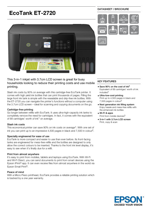
EcoTankET-2720DATASHEET / BROCHUREThis 3-in-1 inkjet with 3.7cm LCD screen is great for busyhouseholds looking to reduce their printing costs and use mobileprinting.Slash ink costs by 90% on average with this cartridge-free EcoTank printer. Itcomes with high yield ink bottles that can print thousands of pages. Filling the large front ink tank is simple with the resealable and drip-free ink bottles. With the ET-2720 you can navigate the printer’s functions without a computer using the 3.7cm LCD screen – ideal for scanning and copying documents on the go.Cartridge-free printingGo longer between refills with EcoTank. It uses ultra-high-capacity ink tanks to completely remove the need for cartridges. In fact, it comes with the equivalent of 88 cartridges' worth of ink 1 on average.Slash ink costsThis economical printer can save 90% on ink costs on average 1. With one set of ink you can print up to an impressive 4,500 pages in black and 7,500 in colour 2.Specially engineered for ease of useEcoTank is more compact and easier to use than ever before. Its front-facing tanks are engineered for mess-free refills and the bottles are designed to only allow the correct colours to be inserted. Thanks to the front ink level display, it's easy to see when it’s finally due for a refill.Print from almost anywhereIt's easy to print from mobiles, tablets and laptops using EcoTank. With Wi-Fi and Wi-Fi Direct, you can send documents to print from smart devices using the Epson iPrint 3 app. It can even receive files from almost anywhere in the world via Epson Email Print 3.Peace of mindWith a Micro Piezo printhead, EcoTank provides a reliable printing solution which is backed by a one year warranty.KEY FEATURESSave 90% on the cost of ink 1Equivalent of 88 cartridges' worth of ink included 1Ultra-low-cost printingPrint up to 4,500 pages in black and 7,500 pages in colour 2Next generation ink filling system Enjoy hassle and mess-free refills with the enhanced ink bottles Wi-Fi & appsPrint from mobile devices 33-in-1 with 3.7cm LCD screen Print, copy & scanPRODUCT SPECIFICATIONSTECHNOLOGY Printing Method Epson Micro Piezo™ print head Minimum Droplet Size 3 pl Ink Technology Dye InkPrinting Resolution 5.760 x 1.440 dpiNozzle Configuration 180 Nozzles black, 59 Nozzles per colour ApplicationHomeAll-in-One Functions Print, Scan, CopyPRINTPrinting Speed ISO/IEC 2473410 pages/min Monochrome, 5 pages/min Colour Maximum Printing Speed 33 pages/min Monochrome (plain paper), 15 pages/min Colour (plain paper)ColoursBlack, Cyan, Yellow, MagentaFirst Page Out from ReadyMonochrome 10 Seconds, Colour 16 Seconds For detailed information on printing speeds please visit http://www.epson.eu/testing.SCANScanning Resolution 1.200 dpi x 2.400 dpi (Horizontal x Vertical)Scanner typeContact image sensor (CIS)PAPER / MEDIA HANDLING Number of paper trays 1Paper Formats A4, A5, A6, B6, Letter, Legal, Executive, B5, 10 x 15 cm, 13 x 18 cm, C6 (Envelope), DL (Envelope), No. 10 (Envelope)DuplexManualMedia Handling Borderless print (up to 10 x 15cm), Manual duplex GENERAL Energy Use 12 W (standalone copying, ISO/IEC 24712 pattern), 0,7 W (sleep mode), 4,3 W (Ready), 0,2 W (Power off)Product dimensions 375 x 347 x 179 mm (Width x Depth x Height)Product weight 4 kgCompatible Operating SystemsMac OS X 10.6.8 or later, Windows 10, Windows 7, Windows 7 x64, Windows 8 (32/64 bit), Windows 8.1, Windows 8.1 x64 Edition, Windows Server 2008 R2, Windows Server 2012 R2, Windows Server 2016, Windows Vista, Windows Vista x64, Windows XP SP3, Windows XP Professional x64 Edition SP2WLAN SecurityWEP 64 Bit, WEP 128 Bit, WPA PSK (TKIP), WPA2 PSK (AES)Mobile and Cloud printing services Epson Connect (iPrint, Email Print, Remote Print Driver), Apple AirPrint, Google Cloud Print ColourBlackOTHER FEATURES LCD screen Type: Colour, Diagonal: 3,7 cm OTHER Warranty12 months Carry in, 30.000 pages Optional warranty extension available LOGISTICS INFORMATIONSKU C11CH42402EAN code 8715946665146Country of OriginPhilippinesEcoTank ET-2720WHAT'S IN THE BOX4 x 65ml individual ink bottles (Bk,C,Y,M)Main unit Power cable Setup guideWarranty documentINK CARTRIDGE COMPATIBILITY104104104104INK BOTTLE YIELD DATAIncluded 3.600 pages* 6.500 pages*Replacement4.500 pages*7.500 pages** Quoted yields are extrapolated based on Epson original methodology from the print simulation of Test Patterns provided in ISO/IEC 24712 with replacement sets of ink. Quoted yields are NOT based on ISO/IEC 24711. Quoted yields may vary depending on the images that you areprinting, the paper type that you are using, the frequency of your prints and environmental conditions such as temperature. During the initial printer setup, a certain amount of ink is used to fill the print head's nozzles,therefore the yield of the initial bundled set can be lower.1. Average number of cartridges required /savingsachieved printing the same number of pages using the ink bottles included within the EcoTank range, excludinghardware price. Comparison made on the average of the A4EcoTank range versus the average of the top 10 best selling models in Western Europe, in the period January 2017– December 2017, as tracked by GfK. Printing costs calculated on the proportion of Standard and XL cartridges as tracked by GfK for the same reference period for the Western European market, using average retail prices. Ink cartridge yields as communicated by the manufacturer’s websites.2. Quoted yields are extrapolated based on Epson original methodology from the print simulation of Test Patterns provided in ISO/IEC 24712 based on the replacement ink bottles. Quoted yields are NOT based on ISO/IEC 24711.Quoted yields may vary depending on the images that you are printing, the paper type that you are using, the frequency of your prints and environmental conditions such as temperature. During the initial printer setup, a certain amount of ink is used to fill the print head's nozzles,therefore the yield of the initial bundled set can be lower.3. 3.Requires a wireless connection to the internet. For more information, supported languages and devices please visit www.epsonconnect.euEpson Deutschland GmbH Otto-Hahn-Str. 4 D-40670 MeerbuschEpson in ÖsterreichInfo-Line: 01 253 49 78 333 www.epson.at。
POWERTEC 161C、191C、231C 和 271C 产品的备用件和电路图说明说明书

IM301509/2020REV09 POWERTEC 161C, 191C, 231C & 271CSpare Parts (1)Figure A: Machine Assembly (3)Figure B: Machine Assembly (6)Figure C: Wire Drive Assembly (8)Miscellaneous Items (not shown in figure A, B, C, D) (8)Electrical Schematic (9)CODE: 50252 (9)CODE: 50246 (9)CODE: 50247, 50248 (10)WEEE (11)Lincoln Electric Bester Sp. z o.o.ul. Jana III Sobieskiego 19A, 58-263 Bielawa, Polandwww.lincolnelectric.euSpare PartsSP50218/50219/50217 REV0307/03ASSEMBLY PAGE NAMEM a c h i n e A s s e m b l yM a c h i n e A s s e m b l yW i r e D r i v e A s s e m b l yM i s c e l l a n e o u s i t e m sCODE NO.: K NO.: FIGURE NO.: A - C -50252 K14040-2 POWERTEC 161C 1 1 1 1 50246 K14045-1 POWERTEC 191C 2 2 2 50246K14045-2POWERTEC 191C A/V230V1PH22250247 K14046-1 POWERTEC 231C 3 3 3 50248 K14047-1 POWERTEC 271C 4 4 4 50248 K14047-2POWERTEC 271C A/V230V1PH444Figure A: Machine AssemblyItem Description Part Number QTY 1 2 3 4 5 6 7 1 BASE R-3019-098-1/08R 1 XPANEL R-3019-101-2/08R 1 X2 FRONTX3 CABLE BUSH 1361-599-399R 2CLAMP 1361-599-398R 2 X4 CABLE5 STICKER 2719-107-156R 1 X6 RESISTOR 1158-112-014R 1 XH1 0917-421-024R 1 X7 LAMPR 1 X8 SWITCHK3 1115-260-0069 KNOB 9ET10491R 1 X10 HANDLE 1361-598-186R 1 X11 STICKER 2719-107-542R 1 X12 POTENCIOMETER 1158-113-304R 3 X13 COVER R-1019-237-1R 1 X14 STICKER 2719-107-120R 1 X15 STICKER 2719-107-728R 1 X16 HINGLE D-3574-007-1/33R 2 X17 DIVIDER R-3019-100-1/08R 1 X18 RUBBER CABLE BUSH 1373-111-331R 1 X19 KNOB D-2846-026-1R 2 XRING 1361-599-670R 2 X20 INSULATING21 STICKER 2719-107-563R 1 XSOCKET 1158-632-009R 2 X22 FUSE23 FUSEF1 1158-660-022R 1 XF2 1158-660-037R 1 X24 FUSE25 KNOB 9ET13639-3R 2 XHUBSTANDARD 0744-000-192R 1 X26 REEL27 PLASIC NUT B11035-1 1 X28 STICKER 2719-107-732R 1 X29 REAR PANEL R-1012-188-1/08R 1 X30 RUBBER BUSH 1373-182-002R 2 X31 GASHOSE 1361-410-005R 2m X32 INPUT CABLE 1125-123-015R 1 X33 FAN 0873-100-032R 1 X34 SHIELD R-1019-111-1/08R 1 XPANEL R-1019-238-1R 1 X35 RIGHTSIDE36 LOCK 0654-610-004R 1 X37 RIGHTLOWERPANEL R-1012-193-1/02R 1 XSIDE38 SLEEVE 1361-599-564R 2 X39 SLEEVE 1361-599-565R 2 X40 SLEEVE 1361-599-720R 2 XWHEELS 1029-660-004R 2 X41 FRONT42 RECTIFIER V1 1156-112-015R 1 X43 CAPACITOR 1158-125-332R 3 X44 RESISTOR 1158-112-015R 1 X45 CHOKE L1 R-4034-049-1R 1 X46 TRANSFORMERT1 R-4034-052-1R 1 XWHEELS 1029-660-007R 1 X47 REAR48 P.C.BOARD R-6042-024-1R 1 XBLOCK 1131-990-005R 8 X 49 TERMINALK1 1115-212-213R 1 X50 CONTACTOR51 GAS SOLENOID 0972-423-004R 1 X52 TERMINAL BLOCK X4 1361-599-328R 1 X53 WORK CABLE R-5041-091-1R 1 X54 STICKER (NOT SHOWN) R-7040-228-3R 1 XFigure B: Machine AssemblyItem Description Part Number QTY 1 2 3 4 5 6 7 PANEL R-3019-120-1/08R 1 - X X X1 FRONT2 STICKER 2719-107-154R 1 - X - -2 STICKER 2719-107-543R 1 - - X X3 STICKER 2719-107-155R 1 - X - -3 STICKER 2719-107-074R 1 - - X -3 STICKER 2719-107-095R 1 - - - X4 POTENCIOMETER 1158-113-304R 3 - X X X5 SOCKET C-2986-001-2R 1 - X X X6 KNOB 9ET10491R 1 - X X X7 SWITCH 1115-260-215R 1 - X - -7 SWITCH 1115-260-214R 1 - - X XSHIELD 1115-299-073R 1 - X X X8 RUBBERS1 1115-270-005R 1 - X X X9 SWITCH10 INTERLOCK D-2722-029-1R 1 - X X X11 LAMP H1 0917-421-024R 1 - X X X12 LEFT SIDE PANEL R-1019-189-1R 1 - X X X13 STICKER 2719-107-052R 1 - X - -13 STICKER 2719-107-203R 1 - - X X14 COVER R-3019-130-1/02R 1 - X X X15 STICKER 2719-107-728R 1 - X X X16 DIVIDER R-1012-207-1/08R 1 - X X X17 RUBBER BUSH 1373-182-002R 3 - X X X18 INSULATING RING 1361-599-670R 2 - X X X19 STICKER R-7040-156-2R 1 - X X X20 FUSE SOCKET 1158-632-009R 2 - X X X21 FUSE F1 1158-660-022R 1 - X X X22 FUSE F2 1158-660-037R 1 - X X X23 REEL HUB STANDARD 0744-000-192R 1 - X X X24 PLASIC NUT B11035-1 1 - X X X25 KNOB D-2846-026-1R 2 - X X X26 SHELF R-3019-123-1/08R 1 - X X X27 TERMINAL BLOCK X1 1131-990-011R 2 - X X X28 RUBBER CABLE BUSH 1373-111-331R 2 - X X X29 STICKER 2719-107-732R 1 - X X X30 SHIELD R-1019-129-1/08 1 - X X X31 STICKER 2719-107-561R 1 - X X X32 KNOB 9ET13639-3R 2 - X X X33 SWITCH 1115-280-005R 1 - X X X34 REAR PANEL R-1012-202-2/08R 1 - X X X35 HOLE PLUG 1361-599-058R 1 - X X X36 RIGHT SIDE PANEL R-1019-190-1R 1 - X X X37 LOCKS 0654-610-004R 2 - X X X38 HINGLE D-3574-007-1/33R 2 - X X X39 RIGHT SIDE LOWER PANEL R-3019-122-1/02R 1 - X X X40 SLEEVE 1361-599-564R 2 - X X X41 SLEEVE 1361-599-565R 2 - X X X42 SLEEVE 1361-599-720R 2 - X X X43 EURO SLEEVE 1361-599-708R 1 - X X X44 BASE R-3019-121-1/08R 1 - X X X45 FRONT WHEELS 1029-660-101R 2 - X X X46 FAN'S BAFFLE R-1012-208-1/08R 1 - X X X47 FAN 0873-100-031R 1 - X X X48 REAR WHEELS 1029-660-201R 2 - X X X49 TRANSFORMER R-4034-061-2R 1 - X - -49 TRANSFORMER R-4034-070-2R 1 - - X -49 TRANSFORMER R-4034-062-2R 1 - - - X50 CHOKE L1 R-4034-067-1R 1 - X X X51 RESISTOR 1158-112-016R 1 - X X X52 RECTIFIER V1 1156-112-205R 1 - X - -52 RECTIFIER V1 1156-112-018R 1 - - X -52 RECTIFIER V1 R-0010-121-3R 1 - - - X53 CAPACITOR 1158-125-331R 3 - X X X54 RESISTOR 1158-112-015R 1 - X X X55 INPUT CABLE R-5041-106-1R 1 - X X X56 GAS HOSE 1361-410-005R 2m - X X X57 CABLE BOX 1361-599-674R 1 - X X X58 CONTACTOR K1 1115-212-211R 1 - X - -58 CONTACTOR K1 1115-212-223R 1 - - X X59 TERMINAL BLOCK 1131-990-005R 8 - X X X60 CAPACITOR C2 1158-121-201R 1 - X X X61 P.C. BOARD R-6042-024-1R 1 - X X X62 TERMINAL BLOCK X4 1361-599-328R 1 - X X X63 GAS SOLENOID 0972-423-004R 1 - X X X64 STICKER (NOT SHOWN) R-7040-228-3R 1 - X X XMiscellaneous Items (not shown in figure A, B, C, D)Item Description Part Number QTY 1 2 3 4 5 6 7 HARNESS R-7040-212-1R 1 X - - -1 WIRINGHARNESS R-7040-213-2R 1 X - - -2 WIRING- X X X3 WIRINGHARNESS R-5041-102-2R 1- X X X HARNESS R-5041-103-2R 14 WIRINGElectrical SchematicRecycle STRef. FeAlCuBrassBoardsPlasticsLiquidCristalExternalElectricCablesCapacitorsFRONTPANEL 1 XEUROSOCKET 2 X XLAMP 3 XSWITCHES 4, 36, 38 X XHANDLE 6 X XDIVIDER 11 XRIGHT SIDE PANEL 7, 9 XLOCK 8 XCOVER 25 XGASSOLENOID 12 X X XP.C.BOARD 13 X FUSESOCKET 14 X XPOTENCIOMETERS 15 X X XTERMINAL BLOCK 16, 18 X X XWIRE FEEDER COMPL. 17 X X X XCONTACTOR 19 X X X XSHIELD 20,38 XFAN 21 X XREARPANEL 22 XGASHOSE 23 XINPUTCABLE 24 X WHEELS 26,31 X XBASE 27 XTRANSFORMER 28 X X XKNOBS 5,37 XRECTIFIER 30 X X X X CABLEBUSH 32,40 XRESISTOR 33 XSOCKET 34 X X XEUROSLEEVE 35 XLEFT SIDE PANEL 41 XSHELF 42 X。
Protek 3201_3290N 中文说明书_东方嘉仪

误动作时
U
U
虽然此仪器的电源可以开机,如有误动作(不正常工作或死机现象)时,请按照下述步骤安 全使用。
1) Protek 3201N/3290N接上电源(电源适配器AC Adapter)。 2) 按Reset 键。 (Reset 键在 Battery 装入口的底面) 3) 不正常工作时, 另外有一种方法是 通过系统菜单(Menu)的测试(TEST)组上选择
PC电脑连接(Connection for PC)……………………………………………………………64
自动电源Auto Power……………………………………………………………………………65
偏置Offset……………………………………………………………………………………66
菜单(Menu)…………………………………………………………………………………67
电 话 :(青 岛 )0532-86069117 (南京)025-52405707 (天津)022-60501825
9
3201N/3290N 用户手册
仪器仪表销售 注册品牌
存储 /读出Save/Load ………………………………………………………………………54
频率计数器(Frequency Counter)………………………………………………………58
RESET 键即可。
电池 (Battery)
U
此仪器使用Ni-MH Rechargeable Battery(镍-氢充电电池;以下称Ni-MH充电电池) 6个,可 以充电后使用。
1) Ni-MH充电电池为消耗品,随着使用时间的增加,Ni-MH充电电池的寿命会缩短。 2) Ni-MH 充电电池的实际使用时间,缩短为刚刚购买时的实际使用时间一半时请更换
条形码读取器BCL300i和BCL301i的01-10 2011版本50117107技术说明书

BCL300i and BCL301iBar code Readerse n 01-10/201150117107T E C H N I C A L D E S C R I P T I O N©All right s re s erved, e s peci a lly the right of reprod u ction, di s tri bu tion a nd tr a n s l a tion. Copying or reprod u ction s in a ny form req u ire the written con s ent of the m a n u f a ct u rer.Prod u ct n a me s us ed witho u t g ua r a ntee of free usab ility.Ch a nge s reflecting technic a l improvement s m a y b e m a de.Table of content s1General information (9)1.1Explanation of s ymbol s (9)1.2Declaration of conformity (9)2S afety notice s (10)2.1General s afety notice s (10)2.2S afety s tandard s (10)2.3Approved purpo s e (10)2.4Workin g s afely (11)3Fa s t commi ss ionin g / operatin g principle (13)3.1Mountin g the BCL300i \ BCL301i (13)3.2Device arran g ement and s election of the mountin g location (13)3.3Electrical connection BCL300i (14)3.4Electrical connection BCL301i (18)3.5S tartin g the device (22)3.6Bar code readin g (24)4Device de s cription (25)4.1About the bar code reader s of the BCL300i s erie s (25)4.2Characteri s tic s of the bar code reader s of the BCL300i s erie s (26)4.3Device con s truction (28)4.4Readin g technique s (32)4.4.1Line s c a nner (s ingle line) (32)4.4.2Line s c a nner with o s cill a ting mirror (33)4.4.3R as ter s c a nner (R as ter Line) (34)4.5S tandalone connectionBCL300i (35)4.6Networkin g - Leuze multiNet plu s BCL301i (36)4.7Leuze multi S can (36)4.8Heater (38)4.9External parameter memory (38)4.10autoReflAct (39)4.11Reference code s (39)4.12autoConfi g (40)Le u ze electronic BCL300i \ BCL301i1Table of content s5S pecification s (41)5.1General s pecification s of the bar code reader s (41)5.1.1Line s c a nner / r as ter s c a nner (41)5.1.2O s cill a ting-mirror s c a nner (43)5.1.3Line s c a nner / r as ter s c a nner with deflection mirror (43)5.2Heatin g model s of the bar code reader s (44)5.2.1Line s c a nner / r as ter s c a nner with he a ter (45)5.2.2O s cill a ting-mirror s c a nner with he a ting (45)5.2.3Line s c a nner / r as ter s c a nner with deflection mirror a nd he a ting (46)5.3Dimen s ioned drawin gs (47)5.3.1Dimen s ioned dr a wing of complete overview of the BCL300i \ BCL301i with M S3xx / MK3xx (47)5.3.2Dimen s ioned dr a wing of complete overview of the BCL300i \ BCL301i with KB301-3000 (47)5.3.3Dimen s ioned dr a wing of line s c a nner with / witho u t he a ting (48)5.3.4Dimen s ioned dr a wing of deflection mirror s c a nner with / witho u t he a ting (49)5.3.5Dimen s ioned dr a wing of o s cill a ting-mirror s c a nner with / witho u t he a ting (50)5.3.6Dimen s ioned dr a wing of M S3xx hood with integr a ted connector s /MK3xx termin a l hood515.3.7Dimen s ioned dr a wing of KB301-3000 c ab le hood (52)5.3.8Dimen s ioned dr a wing of MA100 termin a l b ox (53)5.4Readin g field curve s / optical data (54)5.4.1B a r code ch a r a cteri s tic s (54)5.4.2R as ter s c a nner (55)5.5Readin g field curve s (56)5.5.1High Den s ity (N) - optic s: BCL300i \ BCL301i S/R1 N102 (H) (57)5.5.2High Den s ity (N) - optic s: BCL300i \ BCL301i S/R1 N100 (H) (57)5.5.3High Den s ity (N) - optic s: BCL300i \ BCL301i ON100 (H) (58)5.5.4Medi u m Den s ity (M) - optic s: BCL300i \ BCL301i S/R1 M102 (H) (59)5.5.5Medi u m Den s ity (M) - optic s: BCL300i \ BCL301i S/R1 M100 (H) (59)5.5.6Medi u m Den s ity (M) - optic s: BCL300i \ BCL301i OM100 (H) (60)5.5.7Low Den s ity (F) - optic s: BCL300i \ BCL301i S/R1 F102 (H) (61)5.5.8Low Den s ity (F) - optic s: BCL300i \ BCL301i S/R1 F100 (H) (61)5.5.9Low Den s ity (F) - optic s: BCL300i \ BCL301i OF100 (H) (62)5.5.10Ultr a Low Den s ity (L) - optic s: BCL300i \ BCL301i S/R1 L102 (H) (63)5.5.11Ultr a Low Den s ity (L) - optic s: BCL300i \ BCL301i S/R1 L100 (H) (63)5.5.12Ultr a Low Den s ity (L) - optic s: BCL300i \ BCL301i OL100 (H) (64)2BCL300i \ BCL301i Le u ze electronicTable of content s6In s tallation and mountin g (65)6.1S tora g e, tran s portation (65)6.2Mountin g the BCL300i \ BCL301i (66)6.2.1F as tening with M4 x 5 s crew s (66)6.2.2BT 56 mo u nting device (67)6.2.3BT 59 mo u nting device (69)6.3Device arran g ement (70)6.3.1S electing a mo u nting loc a tion (70)6.3.2Avoiding tot a l reflection – Line s c a nner (71)6.3.3Avoiding tot a l reflection – deflection mirror s c a nner (71)6.3.4Avoiding tot a l reflection – o s cill a ting-mirror s c a nner (72)6.3.5Mo u nting loc a tion (72)6.3.6Device s with integr a ted he a ting (73)6.3.7Po ss i b le re a ding a ngle s b etween BCL300i \ BCL301i a nd ba r code (73)6.4Cleanin g (74)7Electrical connection (75)7.1S afety notice s for the electrical connection (77)7.2Electrical connection BCL300i (78)7.2.1M S300 hood with 2 integr a ted M12 connector s (78)7.2.2MK300 termin a l hood with s pring-lo a ded termin a l s (79)7.2.3MA100 termin a l b ox a nd corre s ponding KB301-3000 c ab le hood (81)7.2.4KB301-3000 c ab le hood (82)7.2.5S t a nd a lone oper a tionBCL300i (82)7.3Electrical connection BCL301i (83)7.3.1M S301 hood with 3 integr a ted M12 connector s (83)7.3.2MK301 termin a l hood with s pring-lo a ded termin a l s (84)7.3.3MA100 termin a l b ox a nd corre s ponding KB301-3000 c ab le hood (86)7.3.4Network oper a tion BCL301i in the Le u ze m u ltiNet pl us (87)7.4Detailed de s cription of the connection s (88)7.4.1PWR / S W IN/OUT - Volt a ge su pply a nd s witching inp u t/o u tp u t s 1 a nd 2 (88)7.4.2S ERVICE – U S B interf a ce (Mini-B type) (90)7.4.3HO S T/BU S IN for BCL300i (91)7.4.4HO S T/BU S IN for BCL301i (93)7.4.5BU S OUT for the BCL301i (94)7.5Leuze multiNet plu s (95)7.5.1Wiring the m u ltiNet pl us (96)7.5.2The BCL301i as network s l a ve (97)7.6Cable len g th s and s hieldin g (97)Le u ze electronic BCL300i \ BCL301i3Table of content s8Di s play element s and di s play (98)8.1LED indicator s BCL300i \ BCL301i (98)8.2Di s play BCL300i \ BCL301i (100)9Leuze webConfi g tool (102)9.1Connectin g the S ERVICE U S B interface (102)9.2In s tallin g the required s oftware (103)9.2.1S y s tem req u irement s (103)9.2.2In s t a lling the U S B driver (103)9.3S tartin g the webConfi g tool (104)9.4S hort de s cription of the webConfi g tool (105)9.4.1Mod u le overview in the Config u r a tion men u (105)10Commi ss ionin g and confi g uration (107)10.1BCL300i (108)10.1.1Me asu re s to b e performed prior to the initi a l commi ss ioning (108)10.1.2S t a rting the device (108)10.2BCL301i - multiNet plu s S lave (109)10.2.1Me asu re s to b e performed prior to the initi a l commi ss ioning (109)10.2.2S t a rting the device (109)10.3Additional s ettin gs for the BCL300i and the BCL301i (110)10.3.1Decoding a nd proce ss ing the re a d d a t a (110)10.3.2Control of the decoding (112)10.3.3Control of the s witching o u tp u t s (113)10.4Tran s mittin g confi g uration data (114)10.4.1Vi a the we b Config tool (114)10.4.2Repl a cing a defective BCL300i \ BCL301i (114)11Online command s (115)11.1Overview of command s and parameter s (115)11.1.1Gener a l 'online' comm a nd s (116)11.1.2’Online’ comm a nd s for s y s tem control (123)11.1.3’Online’ comm a nd s for config u r a tion of s witching inp u t s/o u tp u t s (124)11.1.4’Online’ comm a nd s for the p a r a meter s et oper a tion s (127)12Dia g no s tic s and trouble s hootin g (134)12.1General cau s e s of error s (134)12.2Interface error s (134)4BCL300i \ BCL301i Le u ze electronicTable of content s13Type overview and acce ss orie s (136)13.1Part number code (136)13.2BCL300i (137)13.3BCL301i (138)13.4Connection hood / terminal box acce ss orie s (139)13.5Acce ss ory terminatin g re s i s tor (139)13.6Acce ss ory connector s (139)13.7Acce ss ory U S B cable (139)13.8Acce ss ory mountin g device (139)13.9Reflector acce ss orie s for autoReflAct (139)13.10Acce ss ory ready-made cable s for volta g e s upply (140)13.10.1Cont a ct ass ignment of PWR connection c ab le (140)13.10.2S pecific a tion s of the c ab le s for volt a ge su pply (140)13.10.3Order code s of the c ab le s for volt a ge su pply (140)13.11Acce ss ory ready-made cable s for bu s connection (141)13.11.1Gener a l inform a tion (141)13.11.2Cont a ct ass ignment R S485, connection c ab le KB PB... for m u ltiNet pl us. (141)13.11.3Cont a ct ass ignment R S232, connection c ab le KB SS I/IB S (142)13.11.4Technic a l d a t a of interf a ce connection c ab le s (142)13.11.5Order code interf a ce connection c ab le (142)14Maintenance (144)14.1General maintenance information (144)14.2Repair s, s ervicin g (144)14.3Di s a ss emblin g, packin g, di s po s in g (144)15Appendix (145)15.1Declaration of Conformity (145)15.2A S CII character s et (147)15.3Bar code s ample s (151)15.3.1Mod u le 0.3 (151)15.3.2Mod u le 0.5 (152)Le u ze electronic BCL300i \ BCL301i5Fi g ure s and table sFigure 2.1:Attachment of the stick-on labels with warning notices at the BCL300i \ BCL301i (12)Figure 3.1:BCL300i - MS300 hood with integrated M12 connectors (14)Figure 3.2:BCL300i - MK300 terminal hood with spring-loaded terminals (15)Figure 3.3:Cable fabrication for MK300 terminal hood (15)Figure 3.4:BCL300i - MA100 terminal box with KB301-3000 cable hood (16)Figure 3.5:BCL300i - KB301-3000 cable hood (17)Figure 3.6:BCL301i - MS301 hood with integrated M12 connectors (18)Figure 3.7:BCL301i - MK301 terminal hood with spring-loaded terminals (19)Figure 3.8:Cable fabrication for MK301 terminal hood (19)Figure 3.9:BCL301i - MA100 terminal box with KB301-3000 cable hood (20)Figure 4.1:Line scanner, line scanner with deflection mirror and oscillating-mirror scanner (25)Figure 4.2:Possible bar code orientation (27)Figure 4.3:BCL300i \ BCL301i device construction - line scanner (28)Figure 4.4:BCL300i \ BCL301i device construction -line scanner with deflection mirror (28)Figure 4.5:BCL300i \ BCL301i device construction - oscillating-mirror scanner (29)Figure 4.6:Device construction MS300/MS301 hood with integrated connectors (30)Figure 4.7:Device construction MK300/MK301 hood with integrated connectors (30)Figure 4.8:KB301/3000 cable hood device construction (31)Figure 4.9:MA100 terminal box device construction (31)Figure 4.10:Deflection principle for the line scanner (32)Figure 4.11:Deflection principle for the line scanner with oscillating mirror add-on (33)Figure 4.12:Deflection principle for the raster scanner (34)Figure 4.13:Standalone connectionBCL300i (35)Figure 4.14:Networking possibilities using the multiNet plus (36)Figure 4.15:Scanner arrangement with the multiScan function (37)Figure 4.16:Reflector arrangement for autoReflAct (39)Table 5.1:Specifications of the BCL301i and BCL300i line/raster scanners without heating (41)Table 5.2:Specifications of the BCL301i and BCL300i oscillating-mirror scanners without heating (43)Table 5.3:Specifications of the BCL301i and BCL300i deflection-mirror scanners without heating (43)Table 5.4:Specifications of the BCL301i and BCL300i line/raster scanners with heating (45)Table 5.5:Specifications of the BCL301i and BCL300i oscillating-mirror scanners with heating (46)Table 5.6:Specifications of the BCL301i and BCL300i deflection-mirror scanners with heating (46)Figure 5.1:Dimensioned drawing of complete overview of the BCL300i \ BCL301i with MS3xx / MK3xx (47)Figure 5.2:Dimensioned drawing of complete overview of the BCL300i \ BCL301i with KB301-3000 (47)Figure 5.3:Dimensioned drawing BCL300i \ BCL301i line scanner S...102.. (48)Figure 5.4:Dimensioned drawing BCL300i \ BCL301i deflection mirror scanner S...100 (49)Figure 5.5:Dimensioned drawing BCL300i \ BCL301i oscillating mirror scanner O...100.. (50)Figure 5.6:Dimensioned drawing of MS3xx hood with integrated connectors / MK3xx terminal hood (51)Figure 5.7:Dimensioned drawing of KB301-3000 cable hood (52)Figure 5.8:Dimensioned drawing of MA100 terminal box (53)Figure 5.9:The most important characteristics of a bar code (54)Table 5.7:Raster line cover as a function of the distance (55)Figure 5.10:Zero position of the reading distance (56)Table 5.8:Reading conditions (56)Figure 5.11:"High Density" reading field curve for line scanner without deflection mirror (57)Figure 5.12:"High Density" reading field curve for line scanner with deflection mirror (57)Figure 5.13:"High Density" reading field curve for oscillating-mirror scanners (58)Figure 5.14:Lateral "High Density" reading field curve for oscillating-mirror scanners (58)6BCL300i \ BCL301i Le u ze electronicFi g ure s and table s Figure 5.15:"Medium Density" reading field curve for line scanner without deflection mirror (59)Figure 5.16:"Medium Density" reading field curve for line scanner with deflection mirror (59)Figure 5.17:"Medium Density" reading field curve for oscillating-mirror scanners (60)Figure 5.18:Lateral "Medium Density" reading field curve for oscillating-mirror scanners (60)Figure 5.19:"Low Density" reading field curve for line scanner without deflection mirror (61)Figure 5.20:"Low Density" reading field curve for line scanner with deflection mirror (61)Figure 5.21:"Low Density" reading field curve for oscillating-mirror scanners (62)Figure 5.22:Lateral "Low Density" reading field curve for oscillating-mirror scanners (62)Figure 5.23:"Ultra Low Density" reading field curve for line scanner without deflection mirror (63)Figure 5.24:"Ultra Low Density" reading field curve for line scanner with deflection mirror (63)Figure 5.25:"Ultra Low Density" reading field curve for oscillating-mirror scanners (64)Figure 5.26:Lateral "Ultra Low Density" reading field curve for oscillating-mirror scanners (64)Figure 6.1:Device name plate BCL300i \ BCL301i (65)Figure 6.2:Fastening options using M4x5 threaded holes (66)Figure 6.3:BT 56 mounting device (67)Figure 6.4:Mounting example of BCL300i \ BCL301i with BT56 (68)Figure 6.5:BT 59 mounting device (69)Figure 6.6:Total reflection – line scanner (71)Figure 6.7:Total reflection – line scanner (71)Figure 6.8:Total reflection – BCL300i \ BCL301i with oscillating mirror (72)Figure 6.9:Reading angle for the line scanner (73)Figure 7.1:Location of the electrical connections (76)Figure 7.2:BCL300i - MS300 hood with integrated M12 connectors (78)Figure 7.3:BCL300i - MK300 terminal hood with spring-loaded terminals (79)Figure 7.4:Cable fabrication for MK300 terminal hood (79)Figure 7.5:BCL300i - MA100 terminal box with KB301-3000 cable hood (81)Figure 7.6:BCL300i - KB301-3000 cable hood (82)Figure 7.7:BCL301i - MS301 hood with integrated M12 connectors (83)Figure 7.8:BCL301i - MK301 terminal hood with spring-loaded terminals (84)Figure 7.9:Cable fabrication for MK301 terminal hood (85)Figure 7.10:BCL301i - MA100 terminal box with KB301-3000 cable hood (86)Table 7.1:Pin assignment PWR / SW IN/OUT (88)Figure 7.1:Switching input connection diagram SWIO_1 and SWIO_2 (89)Figure 7.2:Switching output connection diagram SWIO_1 / SWIO_2 (90)Table 7.2:Pin assignment SERVICE – Mini-B type USB interface (90)Table 7.3:Pin assignment HOST / BUS IN BCL300i (91)Figure 7.3:BCL300i - Pin assignments - HOST / BUS IN as RS232 (92)Figure 7.4:BCL300i - Pin assignments - HOST / BUS IN as RS422 (92)Table 7.4:Pin assignment HOST / BUS IN BCL301i (93)Table 7.5:Pin assignment BUS OUTBCL301i (94)Figure 7.5:Leuze multiNet plus system topology (95)Figure 7.6:Leuze multiNet plus system topology (96)Table 7.6:Cable lengths and shielding (97)Figure 8.1:BCL300i \ BCL301i - LED indicators (98)Figure 8.2:BCL300i \ BCL301i - Display (100)Figure 9.1:Connecting the SERVICE USB interface (102)Figure 9.2:The start page of the webConfig tool (104)Figure 9.3:Module overview in the webConfig tool (105)Le u ze electronic BCL300i \ BCL301i7Fi g ure s and table sFigure 10.1:Storing configuration data in the webConfig tool (114)Table 12.1:General causes of errors (134)Table 12.2:Interface error (134)Table 13.2:Type overview BCL300i (137)Table 13.3:Type overview BCL301i (138)Table 13.4:Connection hoods / terminal boxes for the BCL300i \ BCL301i (139)Table 13.5:Terminating resistor for the BCL301i (139)Table 13.6:Connectors for the BCL300i \ BCL301i (139)Table 13.7:Service cable for the BCL300i \ BCL301i (139)Table 13.8:Mounting devices for the BCL300i \ BCL301i (139)Table 13.9:Reflector for autoReflAct operation (139)Table 13.10:PWR cables for the BCL300i \ BCL301i (140)Figure 13.11:Cable configuration multiNet plus connection cables (141)Table 13.12:Interface connection cable for the BCL300i \ BCL301i (142)Figure 15.1:Declaration of conformity BCL300i \ BCL301i (145)Figure 15.2:Connection hood / connector unit declaration of conformity (146)Figure 15.3:Bar code sample labels (module 0.3) (151)Figure 15.4:Bar code sample labels (module 0.5) (152)8BCL300i \ BCL301i Le u ze electronicGeneral information1General information1.1Explanation of s ymbol sThe s ym b ol s us ed in thi s technic a l de s cription a re expl a ined b elow.Attention!This symbol precedes text messages which must strictly be observed. Failure to comply with this information results in injuries to personnel or damage to the equipment.Attention Laser!This symbol warns of possible danger caused by hazardous laser radiation.Notice!This symbol indicates text passages containing important information.1.2Declaration of conformityThe ba r code re a der s of the BCL 300i s erie s h a ve b een developed a nd m a n u f a ct u red in a ccord a nce with the a pplic ab le E u rope a n s t a nd a rd s a nd directive s .Notice!You can find the Declaration of Conformity of the devices in the appendix of the manual on page 145.The m a n u f a ct u rer of the prod u ct, Le u ze electronic Gm b H & Co KG in D-73277 Owen,po ss e ss e s a certified q ua lity assu r a nce s y s tem in a ccord a nce with IS O 9001.S afety notice s2S afety notice s2.1General s afety notice sDocumentationAll entrie s in thi s technic a l de s cription m us t b e heeded, in p a rtic u l a r the pre s ent ch a pter "Sa fety notice s". Keep thi s technic a l de s cription in a sa fe pl a ce. It s ho u ld b e a v a il ab le a t a ll time s.Safety regulationsO bs erve the loc a lly a pplic ab le reg u l a tion s a nd the r u le s of the employer's li ab ility in su r a nce ass oci a tion.RepairRep a ir s m us t only b e c a rried o u t b y the m a n u f a ct u rer or a n au thorized repre s ent a tive.2.2S afety s tandard sThe ba r code re a der s of the BCL300i s erie s were developed, m a n u f a ct u red a nd te s ted ina ccord a nce with the a pplic ab le sa fety s t a nd a rd s. They corre s pond to the s t a te of the a rt.2.3Approved purpo s eAttention!The protection of personnel and the device cannot be guaranteed if the device is operated in a manner not corresponding to its intended use.B a r code re a der s of the BCL300i s erie s a re conceived as s t a tion a ry, high-s peed s c a nner swith integr a ted decoder s for a ll c u rrent ba r code s us ed for au tom a tic o b ject detection.In p a rtic u l a r, u n au thorized us e s incl u de:•in room s with explo s ive a tmo s phere s•oper a tion for medic a l p u rpo s e sAreas of applicationThe ba r code re a der s of the BCL300i s erie s a re e s peci a lly de s igned for the following a re as of a pplic a tion:•S tor a ge technology a nd m a teri a l s h a ndling, in p a rtic u l a r for o b ject identific a tion onf as t-moving tr a n s port s y s tem s•P a llet tr a n s port s y s tem s•A u tomo b ile s ector•Omnidirection a l re a dingS afety notice s2.4Workin g s afelyAttention!Access and changes to the device, except where expressly described in this operating manual, are not authorized.Safety regulationsO bs erve the loc a lly a pplic ab le leg a l reg u l a tion s a nd the r u le s of the employer's li ab ility in su r a nce ass oci a tion.Qualified personnelMo u nting, commi ss ioning a nd m a inten a nce of the device m us t only b e c a rried o u t b y q ua lified per s onnel.Electric a l work m us t b e c a rried o u t b y a certified electrici a n.Attention, laser radiation!If you look into the beam path over a longer time period, the retina of your eye may be damaged!Never look directly into the beam path!Do not point the laser beam of the BCL 300i \ BCL 301i at persons!When mounting and aligning the BCL 300i \ BCL 301i , avoid reflections of the laser beam off reflective surfaces!The BCL 300i \ BCL 301i bar code readers correspond to the EN 60825-1 safety standard for a class 2 laser systems. They also comply with the U.S.21CFR 1040.10regulations for a class II laser product except for deviations pursuant to Laser Notice No. 50, dated July 26, 2001.Radiant Energy: The BCL 300i \ BCL 301i uses a low power visible laser diode. The emitted wavelength is 655nm. The average laser power is less than 1mW in accordance with the definition of laser class 2.Adjustments: Do not attempt any adjustments to or alterations of this product.Do not remove the protective housing of the bar code reader. There are no user-serviceable parts inside.The glass optics cover is the only aperture through which laser radiation may be observed on this product. A failure of the scanner motor, while the laser diode continues to emit a laser beam, may cause emission levels to exceed those for safe operation. The bar code reader has protective devices to prevent this occurrence. If,however, a stationary beam is emitted, the failing bar code reader should be discon-nected from the voltage supply immediately.CAUTION: Use of controls or adjustments or performance of procedures other thanspecified herein may result in hazardous light exposure.S afety notice sThe use of optical instruments or devices in combination with the device increases the danger of eye damage!The housing of the BCL300i \ BCL301i is provided with warning notices A and B above and next to the reading window as shown in the following figure:Fig u re 2.1:Att achment of the s tick-on lab el s with wa rning notice sa t the BCL 300i \ BCL 301iABCL 300i \ BCL 301i Line s canner andM12 M S 3xx connection hoodBCL 300i \ BCL 301i with o s cillatin g mirror and M12 M S 3xx connection hoodBA W a rning: l as er a pert u re BN a me pl a teBCL 300i \ BCL 301i with deflection mirror and M12 M S 3xx connection hoodFa s t commi ss ionin g / operatin g principle3Fa s t commi ss ionin g / operatin g principleBelow yo u will find a s hort de s cription for the initi a l commi ss ioning of the BCL 300i \BCL 301i . Det a iled expl a n a tion s for a ll li s ted point s c a n b e fo u nd thro u gho u t thi s technic a l de s cription.3.1Mountin g the BCL 300i \ BCL 301iThe BCL 300i \ BCL 301i ba r code re a der s c a n b e mo u nted in two different w a y s :•Vi a fo u r M4x6 s crew s on the b ottom of the device.•Vi a a BT 56 mo u nting device in the f as tening groove on the b ottom of the ho us ing.3.2Device arran g ement and s election of the mountin g locationIn order to s elect the right mo u nting loc a tion, s ever a l f a ctor s m us t b e con s idered:•S ize, orient a tion, a nd po s ition toler a nce of the ba r code s on the o b ject s to b e s c a nned.•The re a ding field of the BCL 300i \ BCL 301i in rel a tion to the ba r code mod u le width.•The re su lting minim u m a nd m a xim u m re a ding di s t a nce from the re s pective re a ding field.•The permi ss i b le c ab le length s b etween the BCL 300i \ BCL 301i a nd the ho s t s y s tem depending on which interf a ce i s us ed.•The correct time for d a t a o u tp u t. The BCL 300i \ BCL 301i s ho u ld b e po s itioned in su ch a w a y th a t, t a king into con s ider a tion the time req u ired for d a t a proce ss ing a nd the conveyor b elt s peed, there i s su fficient time to e.g. initi a te s orting oper a tion s on the bas i s of the re a d d a t a .•The di s pl a y a nd control p a nel s ho u ld b e very vi s i b le a nd a cce ss i b le.•For config u ring a nd commi ss ioning with the we b Config tool, the U S B interf a ce s ho u ld b e e as ily a cce ss i b le.For s pecific inform a tion, ple as e refer to ch a pter 6 a nd ch a pter 7.Notice!The beam exits the BCL 300i \ BCL301i as follows for the respective devices:- line scanner parallel to the housing base- deflection mirror 105degrees to the housing base - oscillating mirror perpendicular to the housing base.The black areas in figure 6.2 are the housing base. The best read results are obtained when:•The BCL 300i \ BCL 301i is mounted in such a way that the scanning beam is inci-dent on the bar code at an angle of inclination greater than ±10°…15° to vertical.•The reading distance lies in the middle area of the reading field.•The bar code labels are of good print quality and have good contrast ratios.•You do not use high-gloss labels.•There is no direct sunlight.Fa s t commi ss ionin g / operatin g principle 3.3Electrical connection BCL 300iFor the electric a l connection of the BCL 300i , 4 connection v a ri a nt s a re a v a il ab le.The volta g e s upply (18…30VDC) i s connected a cc. to the connection type s elected.2 freely pro g rammable s witchin g input s /output s for individ ua l a d a pt a tion to the re s pec-tive a pplic a tion a re a l s o a v a il ab le here. Det a iled inform a tion on thi s topic c a n b e fo u nd in ch a pter 7.4.1 a nd ch a pter 7.4.3.MS 300 hood with 2 integrated M12 connectorsFig u re 3.1:BCL 300i - M S 300 hood with integr a ted M12 connector sNotice!The shielding connection is done via the M12 connector housing.Notice!The integrated parameter memory for the simple replacement of the BCL 300i is located in the MS 300.Mini-B U S B s ocket (b ehind protective c a p)M12 pl u g (A-coded)M12 pl u g (B-coded)Blind c a pHood with integr a ted connector sM S 300Fa s t commi ss ionin g / operatin g principleMK 300 terminal hood with spring-loaded terminalsFig u re 3.2:BCL 300i - MK 300 termin a l hood with s pring-lo a ded termin a l sNotice!The integrated parameter memory for simple exchange of the BCL 300i is located in the MK 300.Cable fabrication and s hieldin g connectionRemove a pprox.78mm of the connection c ab le s he a thing. 15mm of s he a th of the s hielded line m us t b e freely a cce ss i b le.Fig u re 3.3:C ab le f ab ric a tion for MK 300 termin a l hoodThe s hield i s au tom a tic a lly cont a cted when the c ab le i s le a d into the met a l s crew fitting a nd f as tened when the cord grip i s clo s ed. Then le a d the individ ua l wire s into the termin a l s a ccording to the di a gr a m. Wire end s leeve s a re not nece ssa ry.Termin a l hood MK 300SERVICE21354GNDD+D-VBID Mini-B U S B s ocket (b ehind protective c ap)T e r m i n a l b l o c k P W R / S W I N /O U TT e r m i n a l b l o c k H O S T / B U S I NTermin a l de s ign a tionMK 300。
新北洋打印机

新北洋打印机一票一控传菜使用说明目录一、硬件环境配置介绍〔设置打印机I P及测试网络通讯〕 (2)1.1、运行 (2)1.2、中英文语言转换功能 (2)1.3、搜索打印机功能 (2)1.4、设置无线参数 (4)1.5、接口固件升级 (6)1.6、查询设备状态 (6)1.7、打印自检页 (8)1.8、接口复位功能 (8)二、泰能软件配置介绍 (9)2.1、数据库 (9)2.2、设置传菜码 (9)2.3、设置传菜码与商品关联 (10)2.4、启动PosCashier 〔或PosTouchCashier〕 (11)2.5、修改传菜单 (11)2.6、参数配置〔PrintConfig.ini〕 (13)三、泰能软件使用介绍 (14)3.1、运行打印效劳器 (14)3.2、正在处理的数据 (14)3.3、已打印的数据 (15)3.4、打印失败的数据 (15)3.5、打印机状态监控 (16)3.6、错误信息 (17)3.7、环境配置信息 (18)一、硬件环境配置介绍〔设置打印机I P及测试网络通讯〕1.1、运行双击B YNetWinConfig.exe 运行配置工具软件,弹出配置工具主界面:1.2、中英文语言转换功能界面中语言列表支持简体中文、英文两种语言转换,默认语言是中文。
1.3、搜索打印机功能搜索功能:点击“搜索打印机〞按钮,谈出选择搜索协议窗口:UDP协议搜索:JK-E01、JK-E02、JK-W01接口设备网络参数必须与用户电脑主机在同一网段内,JK-W01无线网络必须连接正常;IP地址不能存在冲突。
IPX/SPX协议搜索:JK-E02接口设备网络参数可以与用户电脑不在同一网段,但用户主机必须安装IPX/SPX协议支持,并且属性设置帧类型为“Ethernet 802.3〞,网络号设置为“00000000〞。
如果IPX协议设置后还搜索不到JK-E02接口打印机,请按照前提条件2〕设置主机与JK-E02打印机网络参数在同一网段内,再进行搜索。
C 31-MIDAS Manual
51
11.1 安装模拟模块
51
11.2 重新组装MIDAS® 探测器
52
12 找出故障并诊断
53
13 REFLEX®ٛ
54
14 内置的网络服务器
54
14.1 物理的网络组件
54
14.2 网络设置
54
14.3 运行网络浏览器
54
15 典型安装拓扑
56
15.1 常规安装
57
15.2 Modbus/TCP 安装
Honeywell Analytics
操作说明书
毒气/可燃气体/氧气探测器
mda scientific
1
©2004 Honeywell Analytics
目录
1 目录
2 概述
3 产品概述
3.1 主机架
3.1.1 显示器模块
3.1.2 泵模块
3.1.3 传感器暗盒腔
3.2 安装托架座
3.2.1 安装托架
2
8.2 设置、校准和测试模式
30
8.2.1 设置菜单‘ SEt’
31
8.2.2 设置报警 ‘ ALm’
31
8.2.3 设置故障 ‘ FLt’
34
8.2.4 设置校准间距 ‘ CAL’
34
8.2.5 设置日期和时间 ‘timE’
55
8.2.6 设置地址‘ nEt’
35
8.2.7 设置密码 ‘ PWd’
3.2.2 终端模块
3.3 传感器盒
3.3.1 偏致传感器盒
3.4 机壳
4 默认配置
5 安装
5.1 探测器的安装和定位
5.2 机械安装
5.3 样品和排气管道计算
MFC2031-1型微机备用电源自投装置作业指导书
一施工准备报告
工程概要.
1新源发电有限公司一期工程#1、#2机组安装两台2*135MW燃煤机组,工作400V与公用400V自投装置均采用南京东大金智出品的MFC2031-1型系列微机备用电源自投。
1.2工作量:4台微机备用电源自投装置。
2 编制依据
2.1 《继电保护及电网安全自动装置检验条例》
2.2 《继电器检验规程》
2.3 《电气装置安装工程施工及验收规范》
2.4 《电力建设安全工作规程》
2.5 《电继电保护及电网安全自动装置现场工作保安规定》
2.6设计院设计的相关图纸。
2.7 MFC2031-1微机型备用电源自投装置技术说明书及使用说明书、调试记录。
3 施工准备及作业条件
3.1作业准备
试验仪器仪表:MPT-02三相继电保护测试仪或保加玛750单相继电保护测试仪一套。
3.2作业条件
微机备用电源自投装置与柜内部配线已全部结束,定值单已下达,配电室内照明充足,开关柜内无人工作。
3.3作业人员
试验人员2名
4 施工进度
2002年11月22日—2002年11月30日
二施工工序卡
三安全技术措施
四主要安全风险控制计划表
五反馈单(通用格式)。
MFC2003-1微机备用电源自投装置调试报告
旺隆大修工程 #1 机组试验日期: 2007 年 3 月第 1 页共2页设备名称: 380VⅠ段备自投装置一、铭牌三、备自投启动1.高跳:工作段高压侧DL跳闸,联跳低压侧开关ZKK,备自投动作,合备用侧高压开关。
2.低跳:工作段低压侧开关ZKK跳闸,备自投动作,合备用侧高压开关。
3.母线失压启动:4.合备用段高低压侧开关的条件:a.工作段低压开关ZKK已经合开。
四、备自投闭锁1、一次自投动作后,装置闭锁正确。
2、位置闭锁:工作和备用开关全开或全合,HJD位置开,报位置异常,装置闭锁正确。
4、PT断线闭锁正确。
5、外部接点闭锁正确。
五、开关量输入检查:正确。
六、跳合闸出口和信号出口检查:正确。
七、屏幕显示及指示灯显示:正确。
八、试验传动:1、高跳正确2、低跳正确3、母线无压正确九、操作回路绝缘:18MΩ。
十、试验结论:设备合格。
十一、试验仪器:昂立——备用8G 继电保护测试仪精度:0.2试验人员:试验负责人:旺隆大修工程 #1 机组试验日期: 2007 年 3 月第 1 页共2页设备名称:除尘母线Ⅰ段备自投装置一、铭牌三、备自投启动1.高跳:工作段高压侧DL跳闸,联跳低压侧开关ZKK,备自投动作,合备用侧高压开关。
2.低跳:工作段低压侧开关ZKK跳闸,备自投动作,合备用侧高压开关。
3.母线失压启动:4.合备用段高低压侧开关的条件:a.工作段低压开关ZKK已经合开。
四、备自投闭锁1、一次自投动作后,装置闭锁正确。
2、位置闭锁:工作和备用开关全开或全合,HJD位置开,报位置异常,装置闭锁正确。
4、PT断线闭锁正确。
5、外部接点闭锁正确。
五、开关量输入检查:正确。
六、跳合闸出口和信号出口检查:正确。
七、屏幕显示及指示灯显示:正确。
八、试验传动:1、高跳正确2、低跳3、母线无压九、操作回路绝缘:18MΩ。
十、试验结论:设备合格。
十一、试验仪器:昂立——备用8G 继电保护测试仪精度:0.2试验人员:试验负责人:旺隆大修工程 #1 机组试验日期: 2007 年 3 月第 1 页共2页设备名称:除灰母线备自投装置一、铭牌三、备自投启动1.高跳:工作段高压侧DL跳闸,联跳低压侧开关ZKK,备自投动作,合备用侧高压开关。
继电保护专业岗位职责管理规定
继电保护专业岗位职责管理规定201 年月日目录第一章设备职责 (3)第一条.专业设备管辖范围 (3)第二条.继电保护及安全自动装置 (3)第三条.励磁系统 (4)第四条.电测仪表 (4)第五条.自动化系统 (4)第六条.通信系统 (5)第七条.直流电源系统 (5)第二章管理职责 (5)第八条.明确管理职责目的 (5)第九条.主任督导管理职责范围 (6)第十条.班长督导管理职责范围 (7)第三章岗位责任制 (9)第十一条.继电保护主任职责 (9)第十二条.继电保护班长职责 (9)第十三条.继电保护技术员职责 (9)第十四条.继电保护专责工职责 (10)第十五条.继电保护检修工职责 (11)附件 (11)第一章设备职责第一条.专业设备管辖范围设备部继电保护专业设备管辖范围包括继电保护及安全自动装置、励磁系统、电测仪表、自动化(远动)系统、通信系统、直流系统等。
第二条.继电保护及安全自动装置(1)220kV系统:①网络计算机监控系统(NCS);②220kV线路保护装置(CSC-103B、RCS-931AM);③220kV线路失步解列装置(RCS-993E);④220kV母联保护装置(NSR-322);⑤220kV母线保护装置(BP-2B、RCS-915AB);⑥220kV母线故障录波器(ZH-3);⑦网络继电器室试验电源屏;⑧220kV升压站间隔端子箱。
(2)发变组系统:①发电机变压器组保护(RCS-985A、DGT-801B、DGT-801E);②发电机零功率切机装置(RCS-985UP);③自动准同期装置(SID-2CM);④发变组故障录波器(FGL-3000);⑤机组电子设备间试验电源屏;⑥发变组系统端子箱。
(3)6kV高压厂用电系统:①启备变保护(RCS-985T、DGT-801C、DGT-801E);②起备变故障录波器(FGL-3000,在#1发变组故障录波器里);③6kV厂用电源快速切换装置(MFC2000-3A);④厂用电气监控管理系统(ECMS);⑤6kV电压等级保护装置(TV设备NEP982P保护装置、电源进线开关NEP983E保护装置、低压干式变NEP983和NEP984保护装置、电动机NEP998A和NEP998B保护装置)。
- 1、下载文档前请自行甄别文档内容的完整性,平台不提供额外的编辑、内容补充、找答案等附加服务。
- 2、"仅部分预览"的文档,不可在线预览部分如存在完整性等问题,可反馈申请退款(可完整预览的文档不适用该条件!)。
- 3、如文档侵犯您的权益,请联系客服反馈,我们会尽快为您处理(人工客服工作时间:9:00-18:30)。
MFC2031-1型微机备用电源自投装置说明书东大金智软件股份有限公司南京东大金智电气自动化有限公司二00一年八月1目录1.概述 (1)2.主要技术指标 (1)3.原理简介 (2)4.装置软硬件简介 (3)5.主要功能 (6)6.液晶显示菜单说明 (7)7.运行说明 (10)8.设计说明 (10)1MFC2031-1型微机备用电源自投装置说明书1. 概述MFC2031系列微机备用电源自投装置是在MFC2000系列微机厂用电快速切换装置的基础上研制而成的,在硬件和软件上,采用了MFC2000快切装置的成熟技术,结合备自投装置本身的技术要求,进行了相应的调整补充。
装置采用INTEL16位单片机80C196KC ,全中文液晶显示菜单,性能优越,用户界面友好。
装置具有完善的软硬件抗干扰措施,并具备485及RS232通信接口。
MFC2031-1型微机厂用低压备自投装置适用于发电厂低压厂用系统1个备用段(或备用进线)备1个工作段的场合,也可用于其它1备1场合。
2. 主要技术指标2.1装置直流电源a . 额定电压 DC220V 或110Vb . 允许偏差 -20~+15%c . 纹波系数 不大于5% 2.2额定参数a . 交流电压:100V 或57.7Vb . 频率:50HZ2.3功率消耗a . 交流电压回路:当电压为额定值时,每相不大于1V Ab . 直流电源回路:当工作正常时,不大于30W当自投动作时,不大于50W2.4输出接点容量a . 跳合闸接点容量:DC220V ,5A (接通)b . 信号接点容量:DC220V ,50W 2.5电压测量准确度a . 刻度误差:不大于±1%b . 温度变差:在工作环境温度下,不大于±1%c . 综合误差:不大于±2% 2.6工作大气条件2a . 环境温度:-10~+50℃b . 相对湿度:5~95%c . 大气压力:86~106Kpa 2.7 过载能力 a. 交流电压回路:1.5倍额定电压,连续工作。
b.直流电源回路:80%~115%额定电压,连续工作。
3. 原理简介3.1系统接线图典型的厂用低压电源系统如图1所示。
图1 低压厂用电源系统示意图3.2 备自投原理正常运行时,1DL 合,1ZKK 合,2ZKK 分,2DL 分(冷备用)或合(热备用)。
当进行自投时,先跳1ZKK ,确认1ZKK 分开后,再合2D L 和2ZKK 。
3.2.1 备自投就绪状态当以下条件满足时,约10秒后备自投自动进入就绪状态:● 1DL 合,1ZKK 合,2ZKK 分 ●1PT 电压正常,2PT 电压正常3.2.2备自投的起动原则有3● 1DL 跳闸,备自投起动,先联跳1ZKK ,确认其跳开后,合2DL 和 2ZKK 。
● 1ZKK 跳闸,备自投起动,合2DL 和2ZKK 。
● 380V 母线三相失压,电压低于整定值U 2达整定延时时间T 1后,备自投起动,先跳1ZKK ,确认其跳开后再合2DL 和2ZKK 。
3.2.3备自投的闭锁原则有● 刚完成一次自投动作后。
信号:“备投动作”、“备投闭锁”。
● 1DL 、1ZKK 和2DL 、2ZKK 均合上或均打开时,备自投无法进行自投。
信号:“备投闭锁”、“开位异常”。
● 备用无压,即2PT 电压低于整定值U 3时,将不进行自投。
信号“备投闭锁”、“备用无压”。
该功能可根据需要进行投退。
● 备自投起动后,在发出跳1ZKK 命令约0.6s 后,若1ZKK 辅助接点信号未返回,装置将认为1ZKK 拒动,为防止备用电源投入故障而不再发合2ZKK 和2DL 的命令。
信号:“备投闭锁”、“开位异常”。
● 装置检测到1PT 之1相或2相断线后,将自行闭锁自投。
信号“备投闭锁”。
液晶显示“异常报告”中出现“PT 断相”。
● 装置自检出CPU 模块故障后,将自行闭锁自投。
信号:“备投闭锁”、“装置故障”。
● “外部闭锁”接点闭合时,信号:“备投闭锁”装置在以上闭锁情况下,将不再响应起动命令,不能作自投。
在排除故障或情况消失后装置将自动复归,重新进入就绪状态,准备下一次自投。
3.2.4合2ZKK 和2DL 的条件 ● 1ZKK 已跳开●1PT 三相电压低于残压整定值U 14. 装置软硬件简介4.1硬件简介MFC2031-1型微机备自投装置为全微机型,交流采样,数字计算判断。
其硬件系统构成见图2。
● CPU 为Intel 80C196KC 单片机,具有硬件时钟及非易失性RAM ,可以进行动作记录。
● 模拟量输入回路由装置内PT 隔离,电压信号经变换后由AD 采样转换。
● 开关量输入回路与内部电路隔离,CPU 对其去抖后检测。
● 跳合闸出口与内部光电隔离,并经内部逻辑组合以获得高可靠性。
出口接点保持时间约为0.5秒。
4● 信号输出接点与内部光电隔离。
● 具有485及232通信接口。
图2 硬件系统示意图4.2内部插件简介 4.2.1插件布置图图3 内部插件布置图4.2.2插件功能简介 ● CPUCPU插件为整套装置的大脑,所有测量、计算、判断、显示及出口动作指令均由此插件负责完成。
● KBCPU 与面板间接口板。
负责处理键盘、液晶显示、面板信号指示灯等。
● AG模拟量调理板。
将现场PT 二次信号经装置内小PT 变换成小信号,再经调理整形,一路送AD 部分作电压幅值采样计算,另一路送HSI ,可进行频率、相位测量。
插件内小PT 的变比为100:5。
● DIO开入开出板。
将来自控制屏台、保护回路和其它控制设备的开关量5(空接点)隔离变换成电平量,供CPU 板测量判断。
另外,提供经光电隔离后的信号输出接点和装置开关电源+5V 、±15V 和+24V 电压监视输出接点。
● OUT跳合闸出口板。
将CPU 发出的出口指令经逻辑组合后转换成出口继电器的动作信号。
此插件与CPU 板经光电隔离。
共有4路出口。
● PWR电源插件,将DC220V 或DC110V 电压转换成+5V ,±15V 和+24V 电源,供装置内部使用。
插件内特制的电压延时电路能保证在装置上下电过程中不会引起误动作或误发信。
4.3软件简介软件流程示意图如图4所示。
软件系统模块主要有:● AD 采样计算模块● 外部开入量及键盘响应模块 ● 出口、信号处理模块 ● 液晶显示模块 ● 自检模块图4 软件流程示意图65. 主要功能MFC2031-1型微机备用电源自投装置的主要功能如下。
5.1自投功能● 工作电源进线开关1ZKK 跳闸后,自投备用电源。
● 工作母线失压,跳开工作电源,自投备用电源。
5.2联跳自投功能● 工作电源进线开关1DL 跳闸时,联锁跳开1ZKK ,断开工作电源,自投备用电源。
联跳由1DL 辅助接点起动。
5.3闭锁功能● 动作一次后自行闭锁● 备用无压,装置将闭锁(该功能可根据需要进行投退) ● PT 断线,装置将闭锁 ● 自检结果异常,装置将闭锁● 工作、备用进线开关位置异常,装置将闭锁 5.4 自动复归功能当就绪状态的条件满足时,装置能自动进入就绪状态,不须人工复归。
5.5测量显示功能● 液晶显示380V 母线电压U A ,U B ,U C 或U AB ,U BC ,U CA ● 液晶显示备用电源电压U AC (或U BC 、U CA ) ● 面板灯指示工作、备用电源开关合、分位置● 当装置检测到有闭锁或故障情况时,液晶屏上将自动推出“异常报告”画面,显示闭锁或故障原因。
如果是装置内部故障,面板“装置故障”灯将点亮。
也可通过液晶菜单上的“异常报告”子菜单查看闭锁及故障情况。
5.6 传动试验功能本装置可利用液晶菜单中的“试验”子菜单进行备自投动作试验,共可以进行三种试验:“高跳”起动、“低跳”起动及“失压”起动。
这样,可以在不需外部输入信号的条件下,进行传动试验,试验装置出口及信号回路的完好性。
5.7 PT 断线监视当380V 母线一相或二相电压断线时,装置将闭锁告警。
5.8 备用电源监视当备用电源失电时,装置将闭锁告警。
5.9 事件追忆在液晶显示“追忆”子菜单中,将显示最近10次自投动作的时间、动作原7因、动作时有关测量值及出口命令执行情况等参数,可供事故分析参考。
该10组事件具有掉电保持功能。
5.10 密码管理装置内对重要操作如整定值修改、传动试验等均设密码锁功能,以防止误操作。
对密码本身也具有修改功能。
本装置出厂密码设置为1000,用户可以根据需要自行修改。
5.11 通讯功能本装置具有两个通信接口,一个是485接口,可接入DCS 系统或其它上位机系统,进行数据交换;另一个是232接口,可直接插上便携式电脑,利用便携机上的专业应用软件进行参数设定或动作记录保存分析等。
5.12自检功能装置的CPU 、RAM 、ROM 、E 2PROM 和AD 发生故障时,装置将闭锁告警。
5.12 时钟装置内部设有硬件实时时钟,以记录装置动作时间等。
该时钟可以由面板操作或上位系统进行校时,装置预留有GPS 校时接口。
6. 液晶菜单说明6.1 主菜单按“↑”“ ↓”键,可选择子菜单,按确认键进入子菜单。
6.2 测量显示子菜单装置将实时显示工作段Uab ,Ubc ,Uca ,备用段Uab 的值,该值为二次百分值,电压基准值为100V ,例如:Uab=90%,即表示Uab 二次电压值为90V 。
按“取消”键返回主菜单。
8 6.3 定值设置子菜单所有整定参数均储存在E2PROM中,平时,E2PROM允许写入开关应拨向OFF,以免外界强干扰改写定值,需要修改定值时,将开关拨向ON,并输入软件密码。
具体步骤为:打开面板,将最左边CPU插件外侧的小开关拨向ON(下方),按“↑”“↓”上下键可以选择,按“取消”键返回主菜单。
当光标在数字键区域时,当连续按加减键时,数字可连续加减。
定值输入完后必须按“确认”键确认,此时,合理定值将被写入装置的非易失ROM中,为保证可靠性,装置内部自动检查整定定值范围,越限定值将无法整定进装置。
整定完所有的参数,重新检查无误后,将CPU板小开关拨回OFF。
注意:修改定值时必须逐个定值确认。
整定范围:●U1%:0----60%,380V母线电压残压,在工作电源开关已跳开,且母线电压低于该值时,发出合备用电源开关命令。
●U2%:10%---80%,380V母线失压整定值。
当母线三相电压低于该值且达整定延时T1时,装置起动自投。
●U3%:20%---100%,备用无压检定值。
当备用电源电压低于该值时,装置将闭锁自投。
●T1(ms):20---5000失压起动延时。
当母线三相电压低于U2%时间达T1时,装置自行起动,跳开工作电源,投入备用电源。
●通信地址: 0----255。