变压器油中气体及微水在线监测装置
变压器中溶解气体在线监测系统说明书

正确认识变压器状况对于所有的电网工业是极必需的,变压器的在线状态监测也日益重要。
这一信息可以使资产利用达到最大化并且避免因故障而付出昂贵的代价。
变压器绝缘油中溶解气体分析(DGA)及微水测量技术被认为是变压器状况监测的最为重要的手段。
GE旗下KELMAN公司新一代的在线DGA设备,提供了监测变压器状态的必要信息。
在广泛领域内的使用证明了新一代监测仪作为一种有效的手段,为资产管理提供了可靠的信息。
TRANSFIX主要特性z监测单台变压器油箱。
z DGA及微水:8种故障气体加上微水及氮气。
DUALTRANS同时监测两个独立变压器组油箱z DUALTRANS是由凯尔曼公司为两个单相变压器组设计的油中溶解气体及微水在线监测新产品,此系统提供两个独立的绝缘油输入通道,允许对于每台变压器提供完整的油中溶解气体及微水在线监测。
z DUALTRANS测量8种故障气体以及微水。
最先进的光声光谱技术提供了准确以及可靠的测量结果,也使两个变压器箱体内的绝缘油混合可以忽略不计。
z DUALTRANS能够由用户自行设定测量间隔,每隔一小时进行测试,同时测量间隔也能按照报警状态自行调整。
z DUALTRANS可以按照用户需求自动或手动在两台变压器间进行切换。
主要技术特性z一台设备可同时监测两个主油箱。
z8种故障气体及微水分析。
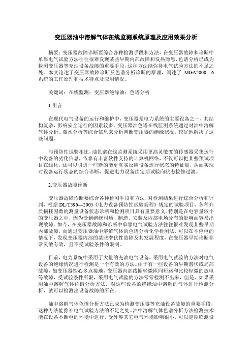
MULTITRANS同时监测三个独立变压器组油箱TRANSPORT X便携式油中溶解气体及微水分析仪在线监测仪型号及监测范围在线监测仪型号 MINITRANS TRANSFIX DUALTRANS MULTITRANS TAPTRANS TRANSPORT X 可监测变压器独立油箱数 1 1 2 3 3 气体测量 测量范围(ppm)氢气(H2) 5—5000 + + + + + +甲烷(CH4) 2—50000 + + + + +乙烷(C2H6) 2—50000 + + + + + +乙烯(C2H4) 2—50000 + + + + +乙炔(C2H2) 0.5—50000 + + + + +一氧化碳(CO) 2—50000 + + + + + +二氧化碳(CO2) 20—50000 + + + + +氧气(O2) 100—50000 + + + +总可燃气体(TDCG)20—50000 +微水 0—100%RS(以ppm形式显示)+ + + + + +氮气(N2) 10—150000 ppm,精确度±15% (自由通气式变压器)+ + +精确度 ±5%最低分辨率下限(取大者)环境参数外部工作温度范围 -40至55℃油样温度范围 -40至120℃工作湿度 10-95%无凝露外壳防护等级 IP 55单相报警继电器 提供常开及常闭触点,5A 250VAC,5A30VDC 多种测量频率 每小时一次至每天一次。
变压器油中溶解气体在线监测说明书

2)检测方式:手动召唤数据和定时自动轮询功能。 3)自检功能:在远程监控中心,本公司能及时的了解设备的运行状态,达到了更
好地为变压器用户,尤其是非电力系统用户服务的目的。 4)设备报警管理:接收运行报警信号,提供报警功能,具有报警条件,产气速率
变电设备在线监测装置检验规范 第2部分:变压器油中溶解气体在线监测装置

多组分在线监测装置技术指标
最高检测限值 μ L/L 2000 1000 1000 1000 1000 5000 15000 最低检测限值或±30%, 测量误差取两者最大值 测量误差要求
II
Q / GDW 540.2 — 2010
变电设备在线监测装置检验规范 第 2 部分:变压器油中溶解气体在线监测装置
1 范围
本标准规定了变压器油中溶解气体在线监测装置的检验条件、专项检验项目、仪器设备和材料、检 验内容及要求、检验结果处理和检验周期。 本标准适用于变压器油中溶解气体在线监测装置的出厂试验、型式试验、入网检测试验、现场试验 和特殊试验。 本标准适用于变压器油中溶解气体在线监测装置专项检测项目的检验。 2 规范性引用文件
6
检验内容及要求
6.1 测量误差试验 6.1.1 制备油样 a) 向油样制备装置中注入新变压器油;对装置中变压器油进行真空脱气或者高纯氮洗脱气,制备 空白油;通入一定量的配油样用气体并与空白油充分混合,配制出一定浓度的“油样” 。制备的油样中 各气体成分浓度由实验室气相色谱仪标定。 b) 油样中所含气体成分浓度应该符合下列要求: 1) 最低检测限值(允许偏差-10%~30%) 、最高检测限值(允许偏差-30%~10%) ; 2) 烃类气体小于 10μ L/L 油样 1 个,10μ L/L 至 150 μ L/L 大致成等差关系的不少于 4 个; 3) 介于 150 μ L/L 和最高检测限值两者之间、气体含量大致成等差关系的不少于 4 个。 c) 油样主要包括多气体成分,必要时也可以配制单气体成分。 6.1.2 油样分析 a) 将“油样”接入变压器油中溶解气体在线监测装置进行分析测试,取相同油样用实验室气相色 谱仪进行分析测试,且实验室测量数据的重复性满足 GB/T17623 中§9.1 的要求,以实验室气相色谱仪 测量结果为基准。 b) 合格判据:按下式计算测量误差,偏差值应满足表 1、表 2 的要求。
变压器油中8种气体在线监测

变压器油中8种气体在线监测1.前言:在现代电力工业的设备运行和维护中,要求在电厂或电站运行的关键变压器特别是发现有异常的变压器上经常进行故障气体,微水含量,局部放电,绕组变形等多种项目的测量。
从这些结果中得到的科学信息是电力部门预计并控制安全服务和运行成本的诸多因素。
随着现代科技的快速发展以及微处理器的引入,在线监测仪器的发展速度正在稳步提高。
在线监测仪器的功能不断改善而价格在逐步下降,使智能化在线检测仪器的广泛应用成为可能。
由于通讯技术的发展使得在线监测的结果能够快速传递到远距的分析和控制中心,在出现故障时不但能及时自动报警并可从多气体比值判断故障性质及类型,采取必要措施,更显示出了他的重要作用。
近年来在国外各大电力部门的应用已经证明,在线监测技术对电力设备的充分利用,提高效益,延长使用寿命以及降低运行维护费用方面都有极大的作用。
自1960年以来,世界电力工业广泛使用变压器油中多种故障气体的色谱分析及多比值,TD 图等判断方法为电力部门的安全高效运行提供重要依据。
但其测量周期较长,脱气误差较大以及耗时较多等问题,尚难满足安全生产和状态检修的要求。
因此,变压器油中多种故障气体的在线监测就成为迫切的需要。
由国家质量监督局颁布的最新国家标准“变压器油中溶解气体分析和判断导则”中指出了变压器绝缘油的产气原理是由于绝缘油和固体绝缘材料在电及热作用下的分解。
低能量放电故障促使最弱的C-H键断裂,主要重新化合成氢气,乙烯在高于甲烷和乙烷的温度下生成。
大量的乙炔是在电弧的弧道中产生。
标准定义了“对判断充油电器设备内部故障有价值的特征气体:即氢气(H2)、甲烷(CH4)、乙烷(C2H6)、乙烯(C2H4)、乙炔(C2H2)、一氧化碳(CO)、二氧化碳(CO2),并说明氧气(O2)和氮气(N2),可作为辅助判断指标。
因此对包含氧气(O2)在内的8种故障气体进行在线监测才能符合中国国家标准的要求,进一步监测氮气(N2)是国际新发展方向。
变压器油中溶解气体在线监测系统原理及应用效果分析
变压器油中溶解气体在线监测系统原理及应用效果分析摘要:变压器故障诊断要综合各种检测手段和方法,在变压器故障和诊断中单靠电气试验方法往往很难发现某些早期内部故障和发热隐患,色谱分析已成为检测变压器等充油设备故障的重要手段,这种方法能弥补电气试验方法的不足之处。
本文论述了变压器故障诊断及色谱分析诊断的原理,阐述了MGA2000—6系统的工作原理和技术特点及应用情况。
关键词:在线监测;变压器绝缘油;色谱分析1.引言在现代电气设备的运行和维护中,变压器是电力系统的主要设备之一,其结构复杂,影响安全运行的因素较多。
变压器油色谱在线监测系统通过对油中溶解气体分析、微水分析等综合信息来分析判断变压器的绝缘状况,较好地解决了这些问题。
与预防性试验相比,油色谱在线监测系统采用更高灵敏度的传感器采集运行中设备的劣化信息,依靠有丰富软件支持的计算机网络,不仅可以把某些预试项目在线化,还可以引进一些新的能更真实反应设备运行状态的特征量,从而实现对设备运行状态的综合诊断,促进电力设备由定期试验向状态检修过渡。
2.变压器故障诊断变压器故障诊断要综合各种检测手段和方法,对检测结果进行综合分析和评判,根据DL/T596—2005《电力设备预防性试验规程》规定的试验项目,各种介质损耗因数的测量设备状态诊断和检测项目具有重要意义。
特别是在电容量较小的变压器之中,因为受到绝缘材质、制造、安装及内部电场分布的影响而容易出现故障。
如今,在变压器故障和诊断中单靠电气试验方法往往很难发现某些早期内部故障,而通过变压器油中溶解气体的色谱分析化学检测法,可以在不停电的情况下,发现变压器内部的某些潜伏性故障及其发展程度,在变压器早期诊断非常灵敏有效,且不受试验条件的限制。
目前,电力系统中采用了大量的充油电气设备,采用电气试验的方法对电气设备的绝缘情况进行检测是一个有效的方法。
由于有一些设备的早期潜伏或局部故障,如变压器铁心多点接地,变压器内部线圈轻微匝间短路和比较轻微的放电等故障,受试验条件所限,采用电气试验的方法常常检测不出来,但是,如果采用油中溶解气体色谱分析方法,对这些设备的绝缘油中溶解的气体进行检测分析,就可以检测出设备故障的所在。
Transfix(主变在线监测装置)用户指南 NG

TRANSFIX
使用手册
10. 如果 TRANSFIX 仍然处于手动取样模式,它将会在一小时后转换到自动测量模式。
测量会在下次计划测量时间开始,如需要立即开始测量,请按下蓝色开始测量按钮并且选择 需要测量的油路。
TRANSFIX 处于 待机模式
TRANSFIX 处 于测量模式
按下停止测量 按钮
正在排油
油过滤器
TRANSFIX 外壳 手动取样口
图 3. 油过滤器及手动取样口仪器前方视图
TRANSFIX 仪 器 的 安 装 配 件 盒 中 提 供 了 一 个 快 速 连 接 组 件 公 头 以 及 一 个 阀 门 组 件 。 TRANSFIX也会确保手动取样时在取样点采得的油样是新鲜的。
获取油样过程如下 (参见图5的流程表): 1. 打开TRANSFIX前门。如果TRANSFIX处于待机状态,转到步骤3。如果仪器正在测量
打开
快速连接件 – 释 放时拉下护套
关闭
装有Luer接头的取样阀组件
图 4. 手动取样装置
7. 当您完成取样时,关闭阀门并且断开您的取样设备。 8. 移除公头及阀门组件,把保护套盖回快速连接件上。 9. 按下白色按钮一次使TRANSFIX仪器返回到自动测量模式。
TRANSFIX 使用手册
第4页
Ver. 40-0110-01 21/08/2007
6. 把外壳向下滑回原处。
6. 油过滤器的清洁
在油路中装有过滤器以防止颗粒物进入TRANSFIX仪器或是变压器中去。过滤器可能需要偶 尔的清洁。在过滤器需要清洁时,TRANSFIX会提示产生了一个非严重性错误——数据文件中会 显示“油压过低”或者“油泵计数器过高”。
拆下过滤器之前,必须关闭 TRANSFIX 设备电源及油路阀门。
变压器油中微量水分检测装置的设计
变压器油中微量水分检测装置的设计作者:王凯周正来源:《现代电子技术》2013年第17期摘要:分析目前常用的变压器油中微量水分检测方法的优缺点,在此基础上设计一种变压器油中微量水分的检测装置。
该检测过程采用物理检测方法,能实现自动定量取样、油水分离、水分汽化、水分检测、微水含量计算。
提出对变压器油中微量水分的总体检测方案,分析检测原理,设计硬件实现电路。
样机测试结果证明该检测装置的有效性。
关键词:变压器油;水分检测;传感器;物理检测中图分类号: TN911.7⁃34; TM406 文献标识码: A 文章编号: 1004⁃373X(2013)17⁃0098⁃030 引言变压器油中的气体杂质和微量水分会降低变压器油的绝缘性能,加速绝缘系统老化,还可导致变压器局部放电击穿及产生气泡,这不仅仅缩短变压器的正常使用寿命,严重时会导致安全事故发生,造成巨大的损失和危害,因此变压器在投入运行以前都需要进行微水检测。
变压器油中微水检测是近些年国内外研究的热点,目前研究的检测方法主要有蒸馏法,卡尔费休法,重量法,介电常数法,各种方法各有优缺点。
蒸馏法原理简单,但检测时间长,受环境影响大,分析效率及准确度低,检测误差大。
卡尔费休法分析速度快,灵敏度高,准确度高,但检测时滴定池的清洁度、滴定参数以及滴定中偶尔出现的假滴定终点现象以及空气的相对湿度都会影响检测结果,而且检测中使用的化学试剂含有一定毒性,操作不当会影响实验人员的健康,废弃的试剂还会对环境造成一定污染。
重量法原理较简单,但油中常混有杂质气体,导致精度不高。
介电常数法可应用于油中微水的在线检测,准确度较高,可以直接获得水分含量,但是检测结果易受电容敏感性和环境温度影响。
为克服以上方法的缺点,本文采用物理方法对变压器油中微量水分进行检测。
该检测方法不需要化学试剂,无任何化学反应,对操作人员无毒害,对环境无污染,运行成本低,整个检测过程绿色环保。
检测过程操作简单,检测速度快,不需要配制和保存化学试剂,能自动实现定量取样、油水分离、水分汽化、水分检测、微水含量计算。
变压器油中溶解气体在线监测装置通用技术规范
200MW风力发电项目工程变压器油中溶解气体在线监测装置通用技术规范2019年7月200MW风力发电项目工程技术规范书变压器油中溶解气体在线监测装置物资采购标准技术规范使用说明1、本标准技术规范分为通用部分、专用部分。
2、项目单位根据需求选择所需设备的技术规范,技术规范通用部分条款及专用部分固化的参数原则上不能更改。
3、项目单位应按实际要求填写“项目需求部分”。
如确实需要改动以下部分,项目单位应填写《项目单位技术差异表》并加盖项目单位公章,与辅助说明文件随招标计划一起提交至招标文件审查会:①改动通用部分条款及专用部分固化的参数;②项目单位要求值超出标准技术参数值;③需要修正污秽、温度、海拔等条件。
经标书审查会同意后,对专用部分的修改形成《项目单位技术差异表》,放入专用部分中,随招标文件同时发出并视为有效,否则将视为无差异。
4、技术规范的页面、标题、标准参数值等均为统一格式,不得随意更改。
5、技术规范专用部分由项目单位根据工程情况编写,其中带“××”的文字和技术参数及“项目单位填写”的部分由各项目单位根据工程实际情况和需要必须全面认真填写;空白部分的参数根据需要选择填写;表格中带下划线的技术参数由项目单位和设计院根据工程具体情况更改,不带下划线的技术参数为固化技术参数,技术规范专用部分技术参数表中项目单位与投标人均不需要填写的部分栏目,项目单位应以“—”表示。
6、投标人应逐项响应技术规范专用部分中相应内容。
填写投标人响应部分,应严格按技术规范专用部分的“招标人要求值”一栏填写相应的投标人响应部分的表格。
投标人填写技术参数和性能要求响应表时,如有偏差除填写“投标人技术偏差表”外,必要时应提供相应试验报告。
7、货物需求一览表中数量各项目单位和设计院必须填写,如不能确定准确数量,可以填写估算数量。
200MW风力发电项目工程技术规范书目录1总则 ........................................................................................................................................................... - 1 -1.1 一般规定 ........................................................................................................................................ - 1 -1.2 投标人应提供的资格文件............................................................................................................. - 1 -1.3 工作范围和进度要求..................................................................................................................... - 1 -1.4 技术资料 ........................................................................................................................................ - 2 -1.5 标准和规范 .................................................................................................................................... - 2 -1.6 必须提交的技术数据和信息......................................................................................................... - 2 -2 性能要求 ................................................................................................................................................... -3 -3 主要技术参数 ........................................................................................................................................... - 3 -5 验收及技术培训 ....................................................................................................................................... - 3 -6 技术服务 ................................................................................................................................................... - 4 -附录A 供货业绩................................................................................................................................. - 5 - 附录B 仪器配置表............................................................................................................................. - 5 -1总则1.1 一般规定1.1.1 投标人应具备招标公告所要求的资质,具体资质要求详见招标文件的商务部分。
变压器油中气体在线监测装置
3.1正常使用条件
3.1.1最高环境气温:+50℃(户外)+40℃(户内)
3.1.2最低环境气温:-40℃(户外)+0℃(户内)
3.1.3最高月平均相对湿度:95%(25℃) (产品内部既不应凝露、也不应积水)
3.1.4大气压力:80kPa~110kPa
3.1.5最大风速:40m/s(离地面10m高、10min平均风速)(户外)
变电站通信网络和系统 系列标准与上一级系统进行通信,实现数据远传、参数设置等功能。
12)在线监测装置应在现场电磁干扰环境下具有良好的稳定性、可靠性。
13)在线监测装置测量数据与试验室试验数据相比对,应满足5.4基本误差要求。
14)监测装置应具有10年以上的使用寿命。
15)在产品寿命周期内,供货商应提供软件免费升级服务。
ES-2011变压器油中溶解气体在线监测装置
技术标书
福州亿森电力设备有限公司
ES-2010变压器油中溶解气体在线监测装置技术规范
变压器油中溶解气体在线监测装置技术规范
1范围
本技术规范规定了变压器油中溶解气体在线监测参数的选取、监测系统的选型、试验和检验、 包装、运输和贮存等方面的技术要求。
本技术规范适用于海南电网公司所属单位对110kV及以上电压等级的变压器、电抗器等变电设 备的油中溶解气体在线监测装置的选用。对其它电力设备选用油中溶解气体在线监测装置时也可参 照执行。
2规范性引用文件
下列文件中的条款通过本办法的引用而成为本办法的条款。凡是注日期的引用文件,其随后所 有的修改单(不包括勘误的内容)或修订版均不适用于本标准,然而,鼓励根据本标准达成协议的 各方研究是否可使用这些文件的最新版本。凡是不注日期的引用文件,其最新版本适用于本办法。
GDDJ-DGA变压器油色谱在线监测说明书
GDDJ-DGA变压器油色谱在线监测装置一、规定用途GDDJ-DGA 变压器油色谱在线监测装置是用于电力变压器油中溶解气体的在线分析与故障诊断,适用于各种电压等级的电力充油变压器、电弧炉变压器、电抗器以及互感器等油浸式高压设备。
二、安全规程从事本设备的安装,投入运行,操作,维护和修理的所有人员◆必须有相应的专业资格。
◆必须严格遵守各项使用说明。
◆不要在数据处理服务器上玩电子游戏、浏览网页。
◆不要在数据处理服务器上任意安装软件,避免不必要的冲突。
违章操作或错误使用可能导致:◆降低设备的使用寿命和监测精度。
◆损坏本设备和用户的其他设备。
◆造成严重的或致命的伤害。
三、GDDJ-DGA 变压器油色谱在线监测装置简介GDDJ-DGA 变压器油色谱在线监测装置可实现自动定量循环清洗、进油、油气分离、样品分析,数据处理,实时报警;快速地在线监测变压器等油浸式电力高压设备的油中溶解故障气体的含量及其增长率,并通过故障诊断专家系统早期预报设备故障隐患信息,避免设备事故,减少重大损失,提高设备运行的可靠性。
该系统作为油色谱在线监测领域的新一代产品,将为电力变压器实现在线远程DGA 分析提供稳定可靠的解决方案,是电力系统状态检修制度实施的有力保障。
GDDJ-DGA 系统是结合了本公司在电力色谱自动全脱气装置运行中近二十年的成功经验,并总结国内外油色谱在线监测的优缺点,倾心打造而成。
该系统保持了我公司产品向来所具有的稳定性、可靠性、准确性等方面的优势:♦在线检测H2、CO、CO2、CH4、C2H4、C2H2、C2H6、H20(可选)的浓度及增长率;♦定量清洗循环取样方式,真实地反应变压器油中溶解气体状态;♦油气分离安全可靠,不污染,排放和不排放变压器油可由用户自己选择;♦采用专用复合色谱柱,提高气体组分的分离度;♦采用进口特制的检测器,提高烃类气体的检测灵敏度;♦高稳定性、高精度气体检测技术,误差范围为± 10%;♦成熟可靠的通信方式,采用标准网络协议,支持远程数据传输;♦数据采集可靠性高,采用过采样技术Δ-∑模数转换器,24位分辨率,自动校准;♦多样的数据显示及查询方式,提供报表和趋势图,历史数据存储寿命为10年;♦环境适应能力强,成功应用于高寒、高温、高湿度、高海拔地区;♦抗干扰性能高,电磁兼容性能满足GB/T17626 与IEC61000 标准;♦提供有两级报警功能,报警信号可远传;♦开放的数据库,可接入电力系统局域网;此外,GDDJ-DGA 系统采用了模块化设计,高性能嵌入式处理器的应用使色谱在线监测系统更加稳定可靠,并具有下列特点:♦更快的分析周期,最小监测周期为40-60分钟,可由用户自行设置,推荐检测周期为24小时检测一次;♦油气分离速度快,仅需10分钟多钟左右,采用特殊的环境适应技术,消除温、湿度变化对气体分配系数的影响;♦分析后的油样采用脱气和缓冲处理技术,消除回注变压器本体的油样中夹杂的气泡,多层隔离式回注油(返油)技术,绝对保证载气不会带进变压器本体中;♦ C2H2最低检测限可达0.1-0.5 μ L/L ;♦采用双回路多模式恒温控制,控温精度达± 0.1 ℃,设备配有自动恒温工业空调;♦采用嵌入式处理器控制系统,将油气分离、数据采集、色谱分析、浓度计算、数据报警、设备状态监控等多功能集于一体,不会出现数据丢失等情况,大大提高了系统的可靠性和稳定性;♦功能接口电路采用光耦隔离设计,进一步提高系统抗干扰性能;♦采用以太网方式,可实现全数字、远程数据传输、控制和参数设置;♦加强系统故障诊断功能,提供改良三比值法、大卫三角法和立方体图示法,给出诊断结果;♦加强系统自检,增加远程维护功能,提供设备异常事件报警;♦支持61850通讯协议,提供同类监测设备组网功能,可实现某一区域的集中远程诊断;♦系统结构采用19”标准机箱和高集成模块化设计,结构紧凑,安装维护简便,操作人性化;♦可扩展性高,可便捷的与其它监测装置集成;♦无钢瓶设计,不需要每年更换载气,大大减少了售后维护量,并且没有高压容器在变压器旁,设备安全性得到充分保障,没有任何安全隐患。
- 1、下载文档前请自行甄别文档内容的完整性,平台不提供额外的编辑、内容补充、找答案等附加服务。
- 2、"仅部分预览"的文档,不可在线预览部分如存在完整性等问题,可反馈申请退款(可完整预览的文档不适用该条件!)。
- 3、如文档侵犯您的权益,请联系客服反馈,我们会尽快为您处理(人工客服工作时间:9:00-18:30)。
T R A N S C O N N E C T User Guide40-0099-04Page Left BlankTRANSCONNECTUsers GuidePN: 40-0099-04Date: June 2, 2008Kelman Ltd. Lissue Industrial Estate EastLissue RoadLisburn BT28 2RBUnited KingdomTel: +44 (0) 28 92 622 915 Fax: +44 (0) 28 92 622 202E–mail: mail@2008 All rights ReservedKELMAN Ltd.Subject to change without noticeTRANSCONNECTUsers GuidePN: 40-0099-04ContentsIntroduction (5)Software Installation (5)USB Driver Installation (5)Getting Started Guide (7)1. Preparations (7)2. Set up a new site (8)3. Set up Communication (9)4. Main Window (15)5. Measurements (16)6. Scheduling (17)7. Alarms (18)8. Inputs (20)9. Settings (21)10. Communications (22)11. Networking (23)12. Security (23)IntroductionTRANSCONNECT is the PC software used with the TRANSFIX family of Transformer Gas Analysers, including TAPTRANS, MULTITRANS and MINITRANS. These will be referred to as “analyser” in this document.NB There will be slight screenshot/functionality deviations depending on the connected analyser. TRANSCONNECT is used to connect to the analyser and:Change basic analyser settings such as Gas Alarm Set points and Analysis Intervals.Monitor the status of the analyser and reset Alarm outputs.Download measurement data from the analyser.View and analyse downloaded analyser data and settings offline.Export measurement data for use with other analysis tools.Software InstallationTRANSCONNECT is included in the PERCEPTION installation.In order to run TRANSCONNECT, it is necessary to have Microsoft .NET Framework Version 2.0 Redistributable Package Beta 2 (x86) installed on the computer. This is available from:/downloads/details.aspx?FamilyID=7ABD8C8F-287E-4C7E-9A4A-A4ECFF40FC8E&displaylang=enUSB Driver InstallationThe USB driver will need to be installed separately. This is done the first time the PC is connected to an analyser via USB.Connect analyser to a USB port on the PC. If already connected then please disconnect from the analyser, wait for about 20 sec. and then reconnect. This will launch the Windows Found New Hardware Wizard. The screen below may be shown. Select “No, not this time” from the options available and then click “Next” to proceed with the installation.Select “Install from a list or specific location (Advanced)” and then click “Next”.Select “Search for the best driver in these locations” and enter the USB folder path in the combo-box (“C:\Progam Files\Kelman Ltd\Perception\TransConnect\USB”) or browse to it by clicking the browse button. Once the folder path has been entered in the box, click next to proceed. The USB folder path can be different than shown here if Windows is not installed on the C: drive or you are using another language versions of Windows than English.Windows should then display a message indicating that the installation was successful. Click “Finish” to complete the installation.The analyser USB connection is now ready for use.Getting Started GuideThis quick guide shows you how to connect to a new site and how to retrieve status, settings and data from the analyser.1. PreparationsBefore using TRANSCONNECT for the first time you need to decide how to connect to the analyser and ensure you have the right cables, modem or RS232 Device Servers at hand. Using TRANSCONNECT via a USBconnection requires that you have installed the USB drivers on your computer as above.2. Set up a new siteTRANSCONNECT is invoked from the Perception program. Open Perception and select File / Transfer Data / Load TransConnect.3. Set up CommunicationThis opens the TRANSCONNECT Communication settings window.This window will list any saved connections to analysers, and also detect any analysers that are connected to the computer. New connections can also be added manually using the “New Connection...” button. This opens the New Connection Wizard.Local connections via USB will only be shown if the USB cable is connected to the analyser. USB connections will be automatically detected and added to the list.Click “Next” and choose the method of communication.Complete the settings for the connection.For serial connection, add the COM port, Baud rate, Parity and Flow Control.port number.For modem connection, select the modem to be used.Add the phone number, including any necessary prefix and country code.For all connections, add the password for the device. The password can be stored with the connection details (check “Remember Password”).Phone numberThe final screen will allow the user to check the connection parameters and change the connection name. It is possible to connect immediately by clicking on “Connect”, or to save the connection by clicking on “Finish”. The new conection will appear in the Connections screen.For saved connections, the parameters can be modified by highlighting the connection and clocking on “Properties”:Select the appropriate parameter on the right hand side to modify the settings.4. Main WindowWhen the “Connect” button is clicked, TRANSCONNECT show the connection progress in the window. For local connections and saved connections where the password has not been saved, the password will be requested. If TRANSCONNECT succeeds in establishing the connection to the analyser then the analyser Main window will be shown.This window mimics the analyser unit and shows the status of the lights and the measurement status. From this screen it is possible to start or stop the measurements, and reset the relays or LED’s.The user can also enter their own identification for the analyser in the ID box .The oil sources for the analyser are also shown on the main screen, with the date and time for the next scheduled measurement. The maximum number of oil sources for each analyser type are:MULTITRANS 3TAPTRANS 3TRANSFIX 1MINITRANS 1If the analyser is measuring a sample then the MEASURING message with the measurement start date and time will be shown. This means that the analyser will probably have an oil sample in its sampling cell and is in the process of extracting and measuring the dissolved gases. In this condition you should never stop the measurement unless absolutely necessary. If the analyser is not measuring then the Standby message will be displayed. In this condition it is safe to disable the periodicsample runs. If the analyser automatic scheduling is not enabled, then Scheduler disabled will be shown.To download the latest measurements and settings, click "Download Measurements". TRANSCONNECT will interrogate the analyser and all analyser settings and measurement data will be downloaded to the PC. The download progress will be shown in the window.All the measurement and settings data held in the analyser internal memory can be downloaded into the computer. If the equipment already exists in the Perception database, only new data will be downloaded. If the equipment does not exist in the Perception database, a new Site, Localization and Equipment will be automatically created and the data will be downloaded into the equipment. The analyser will then be associated with the datafile for that Equipment. See Perception User Guide for more details.The “Refresh” button will update the data on the screen. “Apply” is used to apply any changes made – changes will not be saved unless this button is clicked.To disconnect from the analyser click "Exit".5. MeasurementsThe measurements tab contains the results from the last measurement for each individual oil circuit.6. SchedulingThe scheduling tab allows the user to input Normal, Caution and Alarm mode measurements in intervals between 1 hour and 24 hours. The settings can be changed using the drop-down boxes and the “Apply” button.The “S cheduler Enable” box should be checked for scheduled measurements to continue.For analysers with multiple oil circuits, the measurement intervals for each circuit are set independently of each other. In the event that the measurements are scheduled at the same time, the analyser will prioritise the oil circuits.7. AlarmsThe alarm settings for each individual oil circuit are organized in six pages that can trigger alerts based on gas levels (ppm) of the measured gases and rate of change of each measured gas (ppm/day). Each page has its own independent mapping to the available "Alerts".The analyser has a number of alert options:Relays These are dry contact relay outputs ("Alarm Relays") available on the terminal block within the analyser.Caution and Alarm Indicators. These are the bright yellow and red LED indicators on the front panel of the analyser.Caution mode and Alarm mode. Caution mode and Alarm mode designate two states of the analyser for which the measurement intervals can be set up individually. If no alarm condition exists then the analyser will be in "Normal mode". The corresponding measurement intervals are defined in the analyser Scheduling window. Typically Normal mode would use modest measurement frequency while when in Caution or Alarm mode the measurement frequency can be increased in order to closely monitor the situation in the transformer. Recommended TRANSFIX settings are 4 hours for Normal, 2 hours for Caution and 1 hour for Alarm. For analysers with more than one oil circuit, the Normal and Caution intervals can be increased to avoid conflict.SMS. An SMS message can be sent to a GSM cell phone if a GSM cell modem is installed within the analyser. This option requires the GSM cell phone number to be defined in the analyser Settings window.When an alarm is triggered the mapped "alerts" are activated and remain active untilthe alarm condition is no longer met; the earliest this can happen automatically is after the next oil sample has been analyzed. It is possible to manually reset the relays and indicators using the Status window.Each oil circuit has the facility to set up to six independent alarm screens based on discrete concentration levels or rate-of-change of concentration for each of the measured parameters.The rate of change (ROC) in ppm/day is calculated as the slope of the linear regression line through the (time, ppm) data points. The number of data points to be used for each ROC calculation depends on the number of hours set in the Time Window box. A time window between 1 and 96 hours can be defined.A ROC value calculated from only a few data points has a large variance. To avoid an uncertain ROC value from triggering an alarm it is possible to set the minimum number of samples to be used in the ROC calculation. If for some reason the analyser has recorded less valid samples in the “Time Window”than the set “Minimum Samples” then the ROC calculation will not be completed.Setting a large time window means that many “old” measurements are contributing to the slope calculation meaning a slow response time, and there is a risk that changes in ppm values will not be detected. The right number of hours to set for the “Time Window”is a compromise between the wish to have a fast response to sudden changes and the wish to have a robust detection of the rate change, not disturbed by minor random variations in the ppm values. The formula used for the ROC calculation is:where (n) is the number of valid data points available in the time window and (t i,p i) are the (time, ppm) data points.8. InputsIf analogue inputs have been enabled for the analyser, the name and units of the analogue input can be added in the Inputs screen, along with the zero offset and multiplier or the CT ratio. The instantaneous value of the analogue input is shown.9. SettingsThe settings tab allows the user set the normalisation temperature, clock settings and oil source name.The normalisation temperature for the measurements is usually 20°C.The analyser can also be synchronised with the PC clock and the time zone set. The analyser will automatically adjust for Daylight Saving changes in the set time zone if the box is checked.If there are multiple oil circuits, each oil source can be given a name for identification of the results.The settings tab will also permit the user to input numbers and settings for SMS alerts (see Alarms above).10. CommunicationsThe settings for the communications options can be set up or changed in the Communications tab using the drop-down menus and input boxes. Please refer to the communications option user guide for more details.11. NetworkingSettings for networking can be set up or changed in the Networking tab. Please refer to the communications option user guide for more details.12. SecurityThe analyser can be password-protected for security on both serial channels and Ethernet connection. Click on “Set Password” and input the required password.USB direct connection is not password-protected.The policy for accepting or rejecting connection by dial-up modem, Ethernet or GPRS can also be set using the Accept/Reject buttons. Exceptions to the default can be added using “Edit Exceptions”.。