汽车变速器论文中英文对照资料外文翻译文献
汽车差速器中英文对照外文翻译文献
中英文对照外文翻译(文档含英文原文和中文翻译)Failure analysis of an automobile differential pinion shaft AbstractDifferential is used to decrease the speed and to provide moment increase for transmitting the movement coming from the engine to the wheels by turning it according to the suitable angle in vehicles and to provide that inner and outer wheels turn differently. Pinion gear and shaft at the entrance are manufactured as a single part whereas they are in different forms according to automobile types. Mirror gear which will work with this gear should become familiar before the assembly. In case of any breakdown, they should be changed as a pair. Generally, in these systems there are wear damages in gears. The gear inspected in this study has damage as a form of shaft fracture.In this study, failure analysis of the differential pinion shaft is carried out. Mechanical characteristics of the material are obtained first. Then, the microstructure and chemical compositions are determined. Some fractographic studies are 2005 Elsevier Ltd. All rights reserved.Keywords: Differential; Fracture; Power transfer; Pinion shaft1. IntroductionThe final-drive gears may be directly or indirectly driven from the output gearing of the gearbox. Directly driven final drives are used when the engine and transmission units are combined together to form an integral construction. Indirectly driven final drives are used at the rear of the vehicle being either sprung and attached to the body structure or unsprung and incorporated in the rear-axle casing. The final-drive gears are used in the transmission system for the following reasons [1]:(a) to redirect the drive from the gearbox or propeller shaft through 90°and,(b) to provide a permanent gear reduction between the engine and the driving road-wheels.In vehicles, differential is the main part which transmits the movement coming from the engine to the wheels On a smooth road, the movement comes to both wheels evenly. The inner wheel should turn less and the outer wheel should turn more to do the turning without lateral slipping and being flung. Differential, which is generally placed in the middle part of the rear bridge, consists of pinion gear, mirror gear, differential box, two axle gear and two pinion spider gears.A schematic illustration of a differential is given in Fig, 1. The technical drawing of pinion the fractured pinion shaft is also given in Fig, 2, Fig. 3 shows the photograph of the fractured pinion shaft and the fracture section is indicated.In differentials, mirror and pinion gear are made to get used to each other during manufacturing and the same serial number is given. Both of them are changed on condition that there are any problems. In these systems, the common damage is the wear of gears [2-4]. In this study, the pinion shaft of the differential of a minibus has been inspected. The minibus is a diesel vehicle driven at the rear axle and has a passenger capacity of 15 people. Maximum engine power is 90/4000 HP/rpm, and maximum torque is 205/1600 Nm/rpm. Its transmission box has manual system (5 forward, 1 back). The damage was caused by stopping and starting the minibus at a traffic lights. In this differential, entrance shaft which carries the pinion gear was broken. Various studies have been made to determine the type and possible reasons of the damage. These are:•studies carried out to determine the material of the shaft;•studies carried out to determine the micro-structure;•studies related to the fracture surface.There is a closer photograph of the fractured surfaces and fracture area in Fig. 4. The fracture was caused by taking out circular mark gear seen in the middle of surfaces.2. Experimental procedureSpecimens extracted from the shaft were subjected to various tests including hardness tests and metallographic and scanning electron microscopy as well as the determination of chemical composition. All tests were carried out at room temperature.2.1 Chemical and metallurgical analysisChemical analysis of the fractured differential material was carried out using a spectrometer. The chemical composition of the material is given in Table 1. Chemical composition shows that the material is a lowalloy carburizing steel of the AISI 8620 type.Hardenability of this steel is very low because of low carbon proportion. Therefore, surface area becomes hard and highly enduring, and inner areas becomes tough by increasing carbon proportion on the surface area with cementation operation. This is the kind of steel which is generally used in mechanical parts subjected do torsion and bending. High resistance is obtained on the surface and high fatigue endurance value can be obtained with compressive residual stressby making the surface harder [5-7].In which alloy elements distribute themselves in carbon steels depends primarily on the compound and carbide forming tendencies of each element. Nickel dissolves in the αferrite of the steel since it has less tendency to form carbides than iron Silicon combines to a limited extent with the oxygen present in the steel to form nonmetallic inclusions but otherwise dissolves in the ferrite. Most of the manganese added to carbon steels dissolves in the ferrite. Chromium, which has a somewhat stronger carbide-forming depends on the iron, partitions between the ferrite and carbide phases. The distribution of chromium depends on the amount of carbon present and if other stronger carbide-forming elements such as titanium and columbium amount of carbon present and if other stronger carbide-forming elements such as titanium and columbium are absent. Tungsten and molybdenum combine with carbon to form carbides is there is sufficient carbon present and if other stronger carbide-forming elements such da titanium and columbium are absent. Manganese and nickel lower the eutectoid temperature [8]. Preliminary micro structural examination of the failed differential material is shown in Fig. 5. It can be seen that the material has a mixed structure in which some ferrite exist probably as a result of slow cooling and high Si content. High Si content in this type of steel improves the heat treatment susceptibility as well asan improvement of yield strength and maximum stress without any reduction of ductility [9]. If the micro-structure cannot be inverted to martensite by quenching, a reduction of fatigue limit is observed.There are areas with carbon phase in Fig. 5(a). There is the transition boundary of carburization in Fig. 5(b) and (c) shows the matrix region without carburization. As far as it is seen in there photographs, the piece was first carburized, then the quenching operation was done than tempered. This situation can be understood from blind martensite plates.2.2 Hardness testsThe hardness measurements are carried out by a MetTest-HT type computer integrated hardness tester. The load is 1471 N. The medium hardness value of the interior regions is obtained as obtained as 43 HRC. Micro hard-ness measurements have been made to determine the chance of hardness values along cross-section be-cause of the hardening of surface area dueto carburization. The results of Vickers hardness measurement under a load of 4.903 N are illustrated in Table 2.2.3 Inspection of the fractureThe direct observations of the piece with fractured surfaces and SEM analyses are given in this chapter. The crack started because of a possible problem in the bottom of notch caused the shaft to be broken completely. The crack started on the outer part, after some time it continued beyond the centre and there was only a little part left. And this part was broken statically during sudden starting of the vehicle at the traffic lights. As a characteristic of the fatigue , there are two regions in the fractured surface. These are a smooth surface created by crack propagation and a rough surface created by sudden fracture. These two regions can be seen clearly for the entire problem as in Fig. 4. The fatigue crack propagation region covers more than 80% of the cross-section.Shaft works under the effect of bending, torsion and axial forces which affect repeatedlydepending on the usage place. There is a sharp fillet at level on the fractured section. For this reason, stress concentration factors of the area have been determined. K t = 2.4 value (for bending and tension), and K t = 1.9 value (for torsion) have been acquired according to calculations. These are quite high values for areas exposed to combined loading.These observations and analysis show that the piece was broken under the influence of torsion with low nominal stresses electron microscopy shows that the fracture has taken place in a ductile manner (Fig.6). There are some shear lips in the crack propagation region which is a glue of the plastic shear deformations. Fig. 7 shows the beach marks of the fatigue crack propagation. The distance between any lines is nearly 133 nm.3. ConclusionsA failed differential pinion shaft is analysed in this study. The pinion shaft is produced from AISI 8620 low carbon carburising steel which had a carbursing, quenching and tempering heat treatment process. Mechanical properties, micro structural properties, chemical compositions and fractographic analyses are carried out to determine the possible fracture reasons of the component. As a conclusion, the following statements can be drawn:•The fracture has taken place at a region having a high stress concentration by a fatigue procedure under a combined bending, torsion and axial stresses having highly reversible nature.•The crack of the fracture is initiated probably at a material defect region at the critical location.•The fracture is taken place in a ductile manner.•Possible later failures may easily be prevented by reducing the stress concentration at the critical locationAcknowledgementThe author is very indebted to Prof. S. Tasgetiren for his advice and recommendations during the srudy.References[1]Heisler H. Vehicle and engine technology. 2nd ed. London: SAE International; 1999.[2]Makevet E, Roman I. Failure analysis of a final drive transmission in off-road vehicles. EngFailure Anal 2002;9:579-92.[3]Orhan S, Aktu ¨rk N. Determination of physical faults in gearbox through vibrationanalysis. J Fac Eng Arch Gazi University 2003;18(3):97–106..[4]Tasgetiren S, Aslantas ? K, Ucun I. Effect of press-fitting pressure on the fatiguedamages of root in spur gears. Technol Res: EJMT 2004;2:21–9.[5]Nanawarea GK, Pableb MJ. Failures of rear axle shafts of 575 DI tractors. EngFailure Anal 2003;10:719–24.[6]Aslantas K, Tasgetiren S. A study of spur gear pitting formation and life prediction.Wear 2004;257:1167–75.[7]Savas V, O ¨ zek C. Investigation of the distribution of temperature on a shaft withrespect to the deflection. Technol Res: EJMT 2005;1:33–8.[8]Smith FW. Principles of materials science and engineering. 3rd ed. USA: McGraw-HillSeries; 1996. p. 517–18.[9]ASM metal handbook, vol. 1. Properties and selection, irons, steels, and highperformance alloys; 1991.[10]Voort GFV. Visual examination and light microscopy. ASM handbook metallographyand microstructures. Materials Park (OH): ASM International; 1991. p. 100–65.汽车差速器小齿轮轴的失效分析摘要差速器是用来降低速度增加扭矩并根据合适的角度向两轮传递动力。
自动变速器与驱动桥概述 英文文献加中文翻译
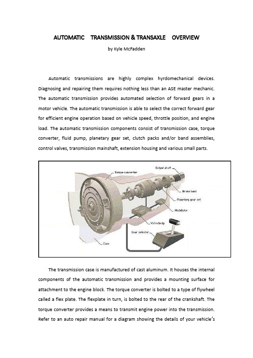
AUTOMATIC TRANSMISSION & TRANSAXLEOVERVIEWby Kyle McFaddenAutomatic transmissions are highly complex hyrdomechanical devices. Diagnosing and repairing them requires nothing less than an ASE master mechanic. The automatic transmission provides automated selection of forward gears in a motor vehicle. The automatic transmission is able to select the correct forward gear for efficient engine operation based on vehicle speed, throttle position, and engine load. The automatic transmission components consist of transmission case, torque converter, fluid pump, planetary gear set, clutch packs and/or band assemblies, control valves, transmission mainshaft, extension housing and various small parts.The transmission case is manufactured of cast aluminum. It houses the internal components of the automatic transmission and provides a mounting surface for attachment to the engine block. The torque converter is bolted to a type of flywheel called a flex plate. The flexplate in turn, is bolted to the rear of the crankshaft. The torque converter provides a means to transmit engine power into the transmission.Refer to an auto repair manual for a diagram showing the details of your vehicle’s torque converter assembly.The torque converter is a doughnut shaped device that is filled with fluid. When the engine is running, the torque converter spins, rotating and pressurizing the fluid using internally mounted blades. The spinning fluid rotates a turbine that is connected to the transmission mainshaft. A separate internal set of blades called a stator helps to direct the fluid into the turbine. The operation of the torque converter can be compared to a powered air fan spinning a non powered air fan. The powered fan will generate moving air, directed at the non powered fan blade, causing it to rotate. The powered fan becomes the driving member, while the non powered fan becomes the driven member. If the air is moving slow enough, very little torque is transmitted from the driving member to the driven member. If you wanted, you could easily stop the rotating fan blade of the non powered fan. However, if the powered fan were to operate at high speed, the non powered fan would be rotating at a much higher speed, making it more difficult to stop. This is the same principal that allows an automatic transmission equipped vehicle to idle in gearand drive down the road without using a mechanical clutch. At idle speed, fluid pressure is low, transmitting very little engine torque through the transmission. When the engine speed is raised, fluid speed and pressure increases, allowing more engine torque to be directed to the transmission. Most torque converters contain an internal locking clutch that is applied at cruise speed. This clutch, called a torque converter clutch, eliminates the slippage that occurs with a torque converter. The torque converter clutch is used as a fuel saving device, and to reduce the amount of heat generated in the transmission. When troubleshooting poor MPG issues, one culprit is a faulty torque converter, though poor MPG would also be present with shifting issues if the torque converter is the cause.Forward speeds and reverse are provided by a gear set called the planetary gears. The planetary gear set consists of a central gear, called the sun gear, placed inside a large gear called an internal gear. Rotating between the internal gear and the sun gear, are small gears, held in a carrier, known as planetary gears. Different gear ratios are made possible by holding one component of the planetary gear set and allowing the other to rotate. For example, if the sun gear were held, the internal gear would be rotated by the planetary gears revolving around the motionless sun gear. This would cause the internal gear to rotate at low speed, while the planetary gears move much faster. This would provide a low gear function for the transmission, since the slow moving internal gear would be used to transmit power to the driving wheels.An internal transmission oil pump is driven by the rotation of the torque converter. The oil pump pressurizes and circulates the transmission fluid used for the operation and lubrication of the transmission. The pressure created by the pump is often referred to as line pressure. Line pressure is utilized by the transmission to signal shift points and operate various transmission components.Bands and clutches are used to hold the components of the planetary gear set to in order to provide different forward gear ratios or reverse. They are operated by line pressure that is directed to a specific band or clutch pack by the transmission shift control valves. The shift control valves operate by responding to changes in linepressure based upon the operation of input devices that signal road speed, throttle position, and engine load. Correcting shifting issues may not involve a costly auto repair job; it may be as simply as adjusting the bands.The input devices used for transmission shift control are the governor, throttle valve, and vacuum modulator. The governor provides road speed information to the transmission to control shift points. It works by increasing line pressure as road speed increases. The throttle valve is connected by linkage to the throttle of the engine. The throttle valve modifies line pressure based on throttle position. This information is needed to vary shift points in response to driving conditions. When the throttle is moved to wide open, the throttle valve will cause send a line pressure signal to the control valves to delay shifting until higher road speed. The vacuum modulator changes shift feel in response to engine load. Since engine intake manifold vacuum changes in response to engine load, manifold vacuum is used as an input signal to the transmission. The vacuum modulator receives vacuum signal from the engine. The vacuum modulator will increase line pressure to stiffen transmission shifting based during heavy engine loads. The increased line pressure will cause clutches and bands to hold tighter and help to diminish slipping.Most vehicles today are equipped with automatic transmissions that use electronic shift controls. The operation of the electronically controlled transmission is similar in principle to the non electric transmission. However, the electronically shifted transmission uses input signals from the vehicle control module to control shift points, rather than a governor and throttle valve. The vehicle control module controls transmission shifting based on engine and transmission data sensors. The throttle position sensor is used in place of the mechanical throttle valve. The vehicle speed sensor is used to replace the governor. Engine load sensors, such as a manifold pressure sensor, are used to control shift feel. A vacuum modulator may still be used by some vehicle makes to assist in shift control. The vehicle control module will utilize this information to operate various shift control solenoids inside the transmission. These shift control solenoids in turn control line pressure to theirrespective shift control valves that in turn apply or release pressure to bands or clutches.The result of using electronic shift controls is an automatic transmission that operates more efficiently to tailor shifting to meet engine demands. Fuel economy and vehicle emission control are enhanced by more precise control of the automatic transmission. Vehicle control modules have the ability to adapt transmission shifting to meet the individual driving patterns of the vehicle. Also internal overheat protection is provided for by the control module’s ability to monitor transmission fluid temperature and change transmission shifting and operation to minimize temperature related damage. On many vehicles, the EEC (Electronic Engine Control) will “learn” a particular driver’s driving style. This information is stored in the EEC’s memory. If the battery is disconnected (during replacement, for example), the vehicle may shift erratically for a short time until the EEC re-learns the driver’s driving style and then reprograms itself. This is important to remember and a little patience can save you a trip to the auto repair shop, ie. after your battery is replaced, drive your vehicle for a day or so and see if the erratic shifting issue is resolved (most likely it will correct itself).The automatic transaxle is an automatic transmission that also contains the final drive for delivering power to the driving wheels. Operation is comparable to the operation of the conventional automatic transmission. With the exception of a differential and axle shafts located in the lower portion of the transaxle. The automatic transaxle is used almost exclusively in front wheel drive vehicles..自动变速器与驱动桥概述自动变速器是高度复杂的精密设备。
汽车主减速器外文文献翻译、中英文翻译、外文翻译

汽车主减速器外文文献翻译、中英文翻译、外文翻译AUTOMOTIWE FINAL DRIVEFINAL DRIVEA final drive is that part of a power transmission system between the drive shaft and the differential. Its function is to change the direction of the power transmitted by the drive shaft through 90 degrees to the driving axles. At the same time. it provides a fixed reduction between the speed of the drive shaft and the axle driving the wheels.The reduction or gear ratio of the final drive is determined by dividing the number of teeth on the ring gear by the number of teeth on the pinion gear. In passenger vehicles, this speed reduction varies from about 3:1 to 5:1. In trucks it varies from about 5:1 to 11:1. To calculate rear axle ratio, count the number of teeth on each gear. Then divide the number of pinion teeth into the number of ring gear teeth. For example, if the pinion gear has 10 teeth and the ring gear has 30 (30 divided by 10), the rear axle ratio would be 3:1. Manufacturers install a rear axle ratio that provides a compromise between performance and economy. The average passenger car ratio is 3.50:1.The higher axle ratio, 4.11:1 for instance, would increase acceleration and pulling power but would decrease fuel economy. The engine would have to run at a higher rpm to maintain an equal cruising speed.The lower axle ratio. 3:1, would reduce acceleration and pulling power but would increase fuel mileage. The engine would run at a lower rpm while maintaining the same speed.The major components of the final driveinclude the pinion gear, connected to the drive shaft, and a bevel gear or ring gearthat is bolted or riveted to the differential carrier. To maintain accurate and proper alignment and tooth contact, the ring gear and differential assembly are mounted in bearings. The bevel drive pinion is supported by two tapered roller bearings, mounted in the differential carrier. This pinion shaft is straddle mounted. meaning that a bearing is located on each side of the pinion shaft teeth. Oil seals prevent the loss of lubricant from the housing where the pinion shaft and axle shafts protrude. As a mechanic, you willencounter the final drive gears in the spiral bevel and hypoid design.Spiral Bevel GearSpiral bevel gears have curved gear teeth with the pinion and ring gear on the same center line. This type of final drive is used extensively in truck and occasionally in older automobiles. This design allows for constant contact between the ring gear and pinion. It also necessitates the use of heavy grade lubricants.Hypoid GearThe hypoid gear final drive is an improvement or variation of the spiral bevel design and is commonly used in light and medium trucks and all domestic rear- wheel drive automobiles. Hypoid gears have replaced spiral bevel gears because they lower the hump in the floor of the vehicle and improve gear-meshing action. As you can see in figure 5-13, the pinion meshes with the ring gear below the center line and is at a slight angle (less than 90 degrees).Figure 5-13.—Types of final drives.This angle and the use of heavier (larger) teeth permit an increased amount of power to be transmitted while the size of the ring gear and housing remain constant. The tooth design is similar to the spiral bevel but includes some of thecharacteristics of the worm gear. This permits the reduced drive angle. The hypoid gear teeth have a more pronounced curve and steeper angle, resulting in larger tooth areas and more teeth to be in contact at the same time. With more than one gear tooth in contact, a hypoid design increases gear life and reduces gear noise. The wiping action of the teeth causes heavy tooth pressure that requires the use of heavy grade lubricants.Double-Reduction Final DriveIn the final drives shown in figure 5-13, there is a single fixed gear reduction. This is the only gear reduction in most automobiles and light- and some medium-duty trucks between the drive shaft and the wheels.Double-reduction final drives are used for heavy- duty trucks. With this arrangement (fig. 5-14) it is not necessary to have alarge ring gear to get the necessary gear reduction. The first gear reduction is obtained through a pinion and ring gear as the single fixed gear reduction final drive. Referring to figure 5-14, notice that the secondary pinion is mounted on the primary ring gear shaft. The second gear reduction is the result of the secondary pinion which is rigidly attached to the primary ring gear, driving a large helical gear which is attached to the differential case. Double-reduction final drives may be found on military design vehicles, such as the 5-ton truck. Many commercially designed vehicles of this size use a single- or double-reduction final drive with provisions for two speeds to be incorporatedFigure 5-14.—Double-reduction final driveTwo-Speed Final DriveThe two-speed or dual-ratio final drive is used to supplement the gearing of the other drive train components and is used in vehicles with a single drive axle (fig. 5-15). The operator can select the range or speed of this axle with a button on the shifting lever of the transmission or by a lever through linkage The two-speed final drive doubles the number of gear ratios available for driving the vehicle under various load and road conditions. For example, a vehicle with a two-speed unit and a five-speed transmission, ten different forward speeds are available. This unit provides a gear ratio high enough to permit pulling a heavy load up steep grades and a low ratio to permit the vehicle to run at high speeds with a light load or no load The conventional spiral bevel pinion and ring gear drives the two-speed unit, but aplanetary gear train is placed between the differential drive ring gear and the differential case. The internal gear of the planetary gear train is bolted rigidly to the bevel drive gear. A ring on which the planetary gears are pivoted is bolted to the differential case. A member, consisting of the sun gear and a dog clutch, slides on one of the axle shafts and is controlled through a button or lever accessible to the operatorWhen in high range, the sun gear meshes with the internal teeth on the ring carrying the planetary gears and disengages the dog clutch from the left bearing adjusting ring, which is rigidly held in the differential carrier. In this position, the planetary gear train is locked together. There is no relative motion between the differential case and the gears in the planetary drive train. The differential case is driven directly by the differential ring gear, the same as in the conventional single fixed gear final drive.When shifted into low range, the sun gear is slid out of mesh with the ring carrying the planetary gears. The dog clutch makes a rigid connection with the left bearing adjusting ring. Because the sun gear is integral with the dog clutch, it is also locked to the bearing adjusting rings and remains stationary. The internal gear rotates the planetary gears around the stationary sun gear, and the differential case is driven by the ring on which the planetary gears are pivoted. This action produces the gear reduction, or low speed, of the axleDIFFERENTIAL ACTIONThe rear wheels of a vehicle do not always turn at the same speed. When the vehicle is turning or when tire diameters differ slightly, the rear wheels must rotate at different speeds.If there were a solid connection between each axle and the differential case, the tires would tend to slide, squeal, and wear whenever the operator turned the steering wheel of the vehicle.A differential is designed to prevent this problem.Driving Straight AheadWhen a vehicle is driving straight ahead, the ring gear, the differential case, the differential pinion gears, and the differential side gears turn as a unit. The two differential pinion gears do NOT rotate on the pinion shaft, because they exert equal force on the side gears. As a result, the side gears turn at the same speed as the ring gear, causing both rear wheels to turn at the same speed.Turning CornersWhen the vehicle begins to round a curve, the differential pinion gears rotate on the pinion shaft. This occurs because the pinion gears must walk around the slower turning differential side gear. Therefore, the pinion gears carry additional rotary motion to the faster turning outer wheel on the turn..Differential speed is considered to be 100 percent. The rotating action of the pinion gears carries 90 percent of this speed to the slowing mover inner wheel and sends 110 percent of the speed to the faster rotating outer wheel. This action allows the vehicle to make the turn without sliding or squealing the wheels.Figure 5-15.—Two speed final drive汽车主减速器主减速器主减速器是在传动轴和差速器之间的一个动力传动系统的组成部分。
自动变速器英文文献翻译

毕业设计外文翻译THE RESEARCHS OFAMT SHIFTING SCHEDULESThe modern automatic transmission is by far,the most complicated mechanical component in today s automobile. It is a type of transmission that siftsitself. A fluid coupling or torque converter is used instead of a manually operated clutch to connect the transmission to the engine.There are two basic types of automatic transmission based on whether the vehicle is rear wheel drive or front wheel drive. On a rear wheel drive car,the transmission is usually mounted to the back of the engine and is located under the hump in the center of the floorboard alongside the gas pedal position. A drive shaft connects the transmission to the final drive which is located in the rear axle and is used to send power to the rear wheels. Power flow on this system is simple and straight forward going from the engine,through the torque converter,then trough the transmission and drive shaftuntil it reaches the final drive where it is split and sent to the two rear transmission.On a front wheel drive car,the transmission is usually combined with the final drive to form what is called a transaxle. The engine on a front wheel drive car is usually mounted sideways in the car with the transaxle tucked under it on the side of the engine facing the reaorf the car. Front axles are connected directly to the transaxle and provide power to front wheels. In this exampl,e power floes from the engine,through the torque converter to a larger chain that sends the power through a 180 degree turn to the transmission thatis along side the engine. From there,the power is routed through the transmission to the final drive where it is split and sent to the two front wheels through the drive axles.There are a number of other arrangements including front drive vehicles where the engine is mounted front to back instead of sideways and there are other systems that drive all four wheels but the two systems described here are by far the most popular. A much less popular rear and is connected by a drive shaft to the torque converter which is still mounted on the engine. This system is found on the new Corvette and is used in order to balance the weight evenly between the front and rear wheels for improved performance and handling. Another rear drive system mounts everything,the engine,transmission and final drive in the rear. This rear engine arrangement is popular on the Porsche。
自动变速器英文文献加翻译

AUTOMATIC TRANSMISSIONThe modern automatic transmission is by far , the most complicated mechanical component in today’s automobile . It is a type of transmission that sifts itself . A fluid coupling or torque converter is used instead of a manually operated clutch to connect the transmission to the engine .There are two basic types of automatic transmission based on whether the vehicle is rear wheel drive or front wheel drive . On a rear wheel drive car , the transmission is usually mounted to the back of the engine and is located under the hump in the center of the floorboard alongside the gas pedal position . A drive shaft connects the transmission to the final drive which is located in the rear axle and is used to send power to the rear wheels . Power flow on this system is simple and straight forward going from the engine , through the torque converter , then trough the transmission and drive shaft until it reaches the final drive where it is split and sent to the two rear transmission .On a front wheel drive car , the transmission is usually combined with the final drive to form what is called a transaxle . The engine on a front wheel drive car is usually mounted sideways in the car with the transaxle tucked under it on the side of the engine facing the rear of the car . Front axles are connected directly to the transaxle and provide power to front wheels . In this example , power floes from the engine , through the torque converter to a larger chain that sends the power through a 180 degree turn to the transmission that is along side the engine . From there , the power is routed through the transmission to the final drive where it is split and sent to the two front wheels through the drive axles .There are a number of other arrangements including front drive vehicles where the engine is mounted front to back instead of sideways and there are other systems that drive all four wheels but the two systems described here are by far the most popular . A much less popular rear and is connected by a drive shaft to the torque converter which is still mounted on the engine . This system is found on the new Corvette and is used in order to balance the weight evenly between the front and rear wheels for improved performance and handling . Another rear drive system mounts everything , the engine , transmission and final drive in the rear . This rear engine arrangement is popular on the Porsche.The modern automatic transmission consists of many components and systems that designed to work together in a symphony of planetary gear sets , the hydraulic system, seals and gaskets , the torque converter , the governor and the modulator or throttle cable and computer controls that has evolved over the years into what many mechanical inclined individuals consider to be an art from .自动变速器对于现代的汽车,自动变速器是一个复杂的组件,这种传递动力的方式,是液力变矩期充当离合器来连接发动机和变速器。
自动变速器发展现状及趋势外文文献翻译、中英文翻译、外文翻译

Current situation and development trend of automatic transmissionFirst, transmission profile1 manual transmission (MT)As we all know, the manual transmission gearbox is one of the most common car, its basic principle is to perform power transmission with a few parallel shafts and several meshing spur or helical gear, namely the input shaft axis and the axis constitute the main gearbox, plus a reverse gear and shaft synchronizer etc.. The working process is as follows: the driver through the drive rod to achieve different gear meshing, and ultimately to achieve different gear ratio gear.2 automatic manual transmission (AMT)Automatic manual transmission (AMT) is actually a machine system to complete the operation of the clutch and select the two movements. The AMT driver is simple, saves the clutch pedal, as long as the driver stepped on the accelerator, the best time selector system will automatically choose to shift, thereby eliminating the engine, clutch and transmission errors, to avoid the wrong bit shift. This is very important for both novice and vehicle reliability. Speed reducer greatly reduces the complexity of driving, so that AMT car driving more simple, worry, and to ensure the lowest power loss. By the selector to complete the driver to step on the clutch shift action, the timing of the shift is more accurate than the driver to complete. Therefore, the background for the growing shortage of energy and the emission of CO2 AMT under increasing pressure, conform to the "energy saving" this door, the best time selector system will automatically choose to shift, thereby eliminating the engine, clutch and transmission errors, to avoid the wrong change gear. This is very important for both novice and vehicle reliability. Speed reducer greatly reduces the complexity of driving, so that AMT car driving more simple, worry, and to ensure the lowest power loss. By the selector to complete the driver to step on the clutch shift action, the timing of the shift is more accurate than the driver to complete. Therefore, the background for the growing shortage of energy and the emission of CO2 AMT under increasing pressure, conform to the "energy saving" this door, the best time selector system will automatically choose to shift, thereby eliminating theengine, clutch and transmission errors, to avoid the wrong change gear. This is very important for both novice and vehicle reliability. Speed reducer greatly reduces the complexity of driving, so that AMT car driving more simple, worry, and to ensure the lowest power loss. By the selector to complete the driver to step on the clutch shift action, the timing of the shift is more accurate than the driver to complete. Therefore, the background for the growing shortage of energy and the emission of CO2 AMT under increasing pressure, conform to the "energy saving" this door, the best time selector system will automatically choose to shift, thereby eliminating the engine, clutch and transmission errors, to avoid the wrong change gear. This is very important for both novice and vehicle reliability. Speed reducer greatly reduces the complexity of driving, so that AMT car driving more simple, worry, and to ensure the lowest power loss. By the selector to complete the driver to step on the clutch shift action, the timing of the shift is more accurate than the driver to complete.3 electronically controlled hydraulic automatic transmission (AT)Electronic control of hydraulic automatic transmission (AT) in recent years, new technologies are constantly in use, it is moving toward multi block, digital control, etc.. Japan's largest automatic transmission manufacturer AISIN AW in 2006, the successful launch of model AA80E 8 speed automatic transmission (see Figure 3), is currently being used in the Lexus LS460 car. This will form a larger total transmission ratio, while the transmission ratio is also closer than the 5 speed transmission. Therefore, the driver can choose the best transmission ratio in almost all driving conditions. Electronic control module can choose more transmission ratio, the transmission ratio depends on the driving conditions, thereby reducing fuel consumption and improve the ride comfort. The optimal matching of engine speed and running state means that the engine improves the power and fuel economy and reduces the running noise.4 continuously variable transmission (CVT)Continuously variable transmission (CVT) is only two groups of removable cone and transmission belt or transmission chain, you can achieve the number of forward gear transmission process. The CVT drive to choose power transmission and the transmission ratio of the transmission chain and the variable cone groove width belt, when cone groove widthchanges, corresponding changes in the driving wheel and the driven wheel drive belt speed contact radius. CVT is a truly stepless, and AT compared with a high operating efficiency, low fuel consumption. Through the application of the market in recent years, the momentum of development is also relatively rapid, currently in our country has been applied to the rapid development of 5 models, more than 6 kinds of. Figure 4 shows the market outlook for the Chinese market in the next few years.At present, the world each big automobile manufacturers in order to improve the competitiveness of their products are vigorously engaged in research and development of CVT, equipped with CVT, TOYOTA, NISSAN car sales are FORD, GM, AUDI and other well-known car brands in the world, CVT's annual production has reached nearly 500 thousand vehicles. It is worth noting that, equipped with CVT car market, from the initial Japan, Europe has penetrated into the North American market, CVT has become the main trend of the development of today's automobile.5 dual clutch transmission (DCT)Dual clutch transmission (DCT) is the first German V olkswagen technology, so in theV olkswagen car system also known as DSG transmission. It can be said to be the world's most advanced, revolutionary transmission system, V olkswagen in 2002 in Wolfsburg, Germany for the first time to show the world the technological innovation. DSG transmission is designed to meet the consumer's desire to drive a sense of movement and fuel-efficient vehicles, for those who love the manual transmission drivers provide a best choice. DSG brings in low fuel consumption and vehicle performance without any loss, also has excellent acceleration and top speed, and the same with the traditional automatic transmission can realize smooth shift without affecting the traction force. Therefore, not only ensures the comfort, but also embodiesDynamic acceleration.Two, the development trend of transmissionAccording to industry estimates, statistical data will be the 2013 European transmission market changes, equipped with a manual transmission car will account for 52%, equippedwith automatic manual transmission will account for 10%, equipped with CVT will account for 2%, equipped with dual clutch transmission will account for 16%, equipped with automatic transmission will account for 20%. But industry experts have pointed out that the prediction was based on the transmission type of the existing new transmission products are constantly in the development process, so in the future transmission car market may also have some changes.1 automatic transmission to multi block developmentWith the automatic transmission car quantity rise, automatic transmission technology has evolved from the past traditional simple 4 speed electronic control (3 solenoid valve) to today's 6, 7, 8 (multi speed solenoid valve control) of the fuzzy control and network control logic. In recent years, the trend of increasing the number of automatic transmission is very obvious, from the traditional 4 speed to the 5, 6, 7, speed. Block number increase means that the total transmission ratio in the range widening, and two adjacent block between the transmission ratio and closer, so the shift time will be in advance, and in the launch to ensure the fuel economy, but also meet the acceleration performance. Now, the world's largest automatic transmission manufacturers have launched more than 5 speed multi speed automatic transmission, such as Z F's 6HP series AISIN; AW company U151/U250E,TF-60SN and TR-60SN; JATCO company's J F506E transmission G M company; T40E,6L50/80E etc..2 mechanical structure gradually simplifiedAlthough the new type of transmission block number in the number, but it does not mean that the transmission of the whole structure and volume become complex and increase, this is because of the combination of mechanical components from a large number of shift actuator control multiple planetary gear to achieve a simple 4 1 variable function, the development of today's 5 shift execution the so-called "Laipeilaijie element control type planetary gear set by logic combination can achieve 6 top 1 down transmission function. The number of parts is reduced by half, and the 6hp series reducer produced by ZF is an example (see Figure 7). At present, the German ZF company and Japan AISIN AW company has successfully pushed the 8 speed automatic transmission, but the gear part is still in use for gear, thus we will find outwhether the traditional Simpson series and Lavinia, or today's Laipeilaijie type planetary gear, are composed of "single planetary gear set single row gear and single row double gear" two forms. To this end, as long as we are familiar with the two kinds of planetary gear transmission on the OK, and when we go to analyze the production of different companies 5, 6, 7, block change.3 electronic control humanizationIn the mechanical and hydraulic aspects seem to be more and more simplified structure, less components, valve number is less, but in the overall control of the electronic control method has become more and more complicated, and requires more precise control, especially in the coordinated torque control, safety control, fuzzy logic control, overlapping shift control others of the more obvious. In order to improve the shift quality, reflect the driving comfort, the engine must realize the torque coordinated control of shift process of automatic transmission, the engine is mainly through the instant change of fuel injection quantity and the ignition delay function to maintain a smooth transition in the shift performance of the shift process of automatic transmission; safety protection control mainly refers to the failure of automatic transmission machinery hydraulic, electronic control, and the fault can be a greater threat to the transmission, in order to protect the transmission from further damage, protected by an automatic transmission through the computer receives the sensor information after the start; fuzzy logic control function, it is a microcomputer to imitate human brain function, can predict to the driver's next move, and finally realize the optimum shift time control and shift point switch Such control. Here we focus on understanding the overlapping shift control, this is because many of the maintenance staff is still relatively vague understanding. The so-called overlapping shift control this new words explanation is that shifting process is actually the process of friction friction element, in the common friction clutch and clutch or clutch and brake in the shift, if the friction torque of replacement process will cause improper timing, sharp fluctuations in output torque. The replacement of the friction torque between the two clutches or between the clutch and the brake, there will always be more or less interruption interval or overlap. Overlapping or excessive overlap, will produce undue shift impact. Overlap is the separation of the clutch to be separated too fast oil separation, to be combinedwith the clutch failed to establish sufficient oil pressure, thus the emergence of the two clutch torque transmission phenomenon. In this time of overlap, the output torque is first decreased too much, and then rise sharply, resulting in a larger torque disturbance. At the same time, the engine speed can not get a smooth transition, the first is due to the reduction of load growth, but also because of the rapid increase in load and speed down. Overlap is too much in the combination of the clutch has been able to transmit a lot of torque, the clutch should be separated from the oil separation is not very good, so there are two agencies working at the same time. In a short period of time, the two gears overlap, so that the engine and the output shaft are subject to braking, so the output shaft has a large torque disturbance. Subsequently, the clutch should be separated so that the transmission4 the number of actuators is increasing, and the type of control is changingYou will find that the automatic transmission actuator solenoid valve number increasing, the switch type solenoid valve is less, while the frequency is too much, the number of mechanical valve and control circuit is also less (more solenoid valve control is to improve the quality of the shift). A slide valve may be based on the conversion of the oil to achieve multi-purpose, a simple solenoid valve will be multi-purpose, it can achieve shift control, but also can take charge of oil pressure control. In the past the traditional type of electronic control automatic transmission, switching circuit is switched by shifting the solenoid valve to control the switching circuit, the circuit is a switching type (for shifting actuator junction without excessive vibration, the buffer control circuit is usually used in throttling and storage device to achieve slow control). The actuator in the 6HP series, the 6 has a pulse width modulation solenoid valve features high flow high frequency, 1 of them (E D S5) is mainly used to complete the system pressure regulating function, the other 1 (E D S6) is used to complete the engine and the transmission gearbox mechanical connection function (T C C) and the remaining 4 solenoid valve (E D S1-A, E D S2-B, E D S3-C, E D S4-E/D) respectively control 5 shift actuators of engagement and separation, that is to say the shift circuit controlled by the switch into the original regulation, thus greatly improve the shift quality. Shift control, but also can undertake the oil pressure control. In the past the traditional type of electronic control automatic transmission, switching circuit is switched by shifting thesolenoid valve to control the switching circuit, the circuit is a switching type (for shifting actuator junction without excessive vibration, the buffer control circuit is usually used in throttling and storage device to achieve slow control). The actuator in the 6HP series, the 6 has a pulse width modulation solenoid valve features high flow high frequency, 1 of them (E D S5) is mainly used to complete the system pressure regulating function, the other 1 (E D S6) is used to complete the engine and the transmission gearbox mechanical connection function (T C C) and the remaining 4 solenoid valve (E D S1-A, E D S2-B, E D S3-C, E D S4-E/D) respectively control 5 shift actuators of engagement and separation, that is to say the shift circuit controlled by the switch into the original regulation, thus greatly improve the shift quality.自动变速器发展现状及趋势一、变速器简介1.手动变速器(MT)大家知道,手动变速器是汽车中最常见的变速器之一,其基本原理是用几根平行轴及若干相啮合的直齿或斜齿齿轮进行动力传递,即由输入轴、轴出轴和中间轴构成变速器的主体,再加上一根倒挡轴及同步器等部件。
变速器汽车车辆外文文献翻译、中英文翻译、外文翻译

变速器汽车车辆外文文献翻译、中英文翻译、外文翻译变速器变速箱通常不得不在舒适性和效率之间做出选择,但一种新型的“犬牙啮合式”变速箱可以同时改善这两种性能。
随着排放法规的日趋严格,汽车制造商为降低排放的努力已不再局限于改善燃烧过程和后期处理。
许多公司认为,现代发动机技术已经发展到这样一个阶段:与投入巨额开发成本相比,技术进步带来的收效却很小。
因此为了改善排放,最重要的是要着眼于整车的性能。
作为车上第二昂贵的部件,变速箱理所当然地成为第二步改善的目标。
所有变速箱技术中,手动变速箱的效率最高,输出功率可达输入功率的96%。
但并不是所有人都能驾驭手动变速箱,也不是所有人都愿意用它。
因为用手动变速箱需要踩离合器,这在交通繁忙的时候很不舒服。
驾驶员容易疲劳。
而由扭矩中断导致的“点头”效应也会使乘客很难受。
由于驾驶员操纵离合器而产生的扭矩中断是手动变速箱的主要缺点。
在换档加速时,每升高一档,驾驶员都必须通过松开油门并踩下离合器来使扭矩暂时中断。
完成整个过程大概只需一秒钟,但在这段时间里车辆会暂时停止加速,速度也会降低。
与此截然相反的是传统的自动变速箱。
由于采用了变矩器,这种变速箱的换档质量不错但效率相对较差——即使最近有所改进。
因此,最近进行了许多研究,试图发现传统自动变速箱的有效替代方案。
主要的技术仍是无级变速(CVT)、双离合器变速(DCT)和手自一体(AMT)变速器。
它们在不同的方面优于传统的行星齿轮式自动变速器。
无级变速器采用带链或锥盘滚轮来产生无限多种变速比。
与传统自动变速器相比,其效率和成本都有所改善。
之所以有这些优点,是因为它结构简单。
这种变速器的零部件很少,通常只有一根橡胶或金属传动带、一个液压作用的驱动带轮、一个机械扭矩感应式驱动带轮、一些微处理器和传感器等。
这种变速器的工作原理是改变两个带轮表面之间的距离。
带轮上挂传动带的地方开了V形的槽。
一侧的带轮沿轴向固定,另一侧的带轮可在液压的作用下移动。
汽车变速器的设计外文文献翻译、中英文翻译、外文翻译
汽车变速器的设计外文文献翻译、中英文翻译、外文翻译A manual n。
also known as a standard n。
XXX。
It consistsof gears。
synchros。
roller bearings。
shafts。
and gear selectors。
The main clutch assembly is used to engage and disengage the engine from XXX gears are used to select the desired。
and the sector fork moves gears from one to another using the gearshift knob。
Synchros are used to slow the gear to a。
before it is XXX。
The counter shaft holds the gears in place and against the main input and output shaft。
Unlike automatic ns。
XXX。
as there isno XXX。
Note: XXX "n Shifter" was deleted as it had no XXX.)XXX have four to six forward gears and one reverse gear。
However。
some cars may have up to eight forward gears。
while semi trucks XXX by the number of forward gears。
such as a 5-speed standard n.The n of a standard n includes three shafts: the input shaft。
- 1、下载文档前请自行甄别文档内容的完整性,平台不提供额外的编辑、内容补充、找答案等附加服务。
- 2、"仅部分预览"的文档,不可在线预览部分如存在完整性等问题,可反馈申请退款(可完整预览的文档不适用该条件!)。
- 3、如文档侵犯您的权益,请联系客服反馈,我们会尽快为您处理(人工客服工作时间:9:00-18:30)。
中英文对照资料外文翻译文献汽车变速器设计----------外文翻译我们知道,汽车发动机在一定的转速下能够达到最好的状态,此时发出的功率比较大,燃油经济性也比较好。
因此,我们希望发动机总是在最好的状态下工作。
但是,汽车在使用的时候需要有不同的速度,这样就产生了矛盾。
这个矛盾要通过变速器来解决。
汽车变速器的作用用一句话概括,就叫做变速变扭,即增速减扭或减速增扭。
为什么减速可以增扭,而增速又要减扭呢?设发动机输出的功率不变,功率可以表示为 N = w T,其中w是转动的角速度,T是扭距。
当N固定的时候,w与T是成反比的。
所以增速必减扭,减速必增扭。
汽车变速器齿轮传动就根据变速变扭的原理,分成各个档位对应不同的传动比,以适应不同的运行状况。
一般的手动变速器内设置输入轴、中间轴和输出轴,又称三轴式,另外还有倒档轴。
三轴式是变速器的主体结构,输入轴的转速也就是发动机的转速,输出轴转速则是中间轴与输出轴之间不同齿轮啮合所产生的转速。
不同的齿轮啮合就有不同的传动比,也就有了不同的转速。
例如郑州日产ZN6481W2G型SUV车手动变速器,它的传动比分别是:1档3.704:1;2档2.202:1;3档1.414:1;4档1:1;5档(超速档)0.802:1。
当汽车启动司机选择1档时,拨叉将1/2档同步器向后接合1档齿轮并将它锁定输出轴上,动力经输入轴、中间轴和输出轴上的1档齿轮,1档齿轮带动输出轴,输出轴将动力传递到传动轴上(红色箭头)。
典型1档变速齿轮传动比是3:1,也就是说输入轴转3圈,输出轴转1圈。
当汽车增速司机选择2档时,拨叉将1/2档同步器与1档分离后接合2档齿轮并锁定输出轴上,动力传递路线相似,所不同的是输出轴上的1档齿轮换成2档齿轮带动输出轴。
典型2档变速齿轮传动比是2.2:1,输入轴转2.2圈,输出轴转1圈,比1档转速增加,扭矩降低。
当汽车加油增速司机选择3档时,拨叉使1/2档同步器回到空档位置,又使3/4档同步器移动直至将3档齿轮锁定在输出轴上,使动力可以从轴入轴—中间轴—输出轴上的3档变速齿轮,通过3档变速齿轮带动输出轴。
典型3档传动比是1.7:1,输入轴转1.7圈,输出轴转1圈,是进一步的增速。
当汽车加油增速司机选择4档时,拨叉将3/4档同步器脱离3档齿轮直接与输入轴主动齿轮接合,动力直接从输入轴传递到输出轴,此时传动比1:1,即输出轴与输入轴转速一样。
由于动力不经中间轴,又称直接档,该档传动比的传动效率最高。
汽车多数运行时间都用直接档以达到最好的燃油经济性。
换档时要先进入空档,变速器处于空档时变速齿轮没有锁定在输出轴上,它们不能带动输出轴转动,没有动力输出。
一般汽车手动变速器传动比主要分上述1-4档,通常设计者首先确定最低(1档)与最高(4档)传动比后,中间各档传动比一般按等比级数分配。
另外,还有倒档和超速档,超速档又称为5档。
当汽车要加速超过同向汽车时司机选择5档,典型5档传动比是0.87:1,也就是用大齿轮带动小齿轮,当主动齿轮转0.87圈时,被动齿轮已经转完1圈了。
倒档时输出轴要向相反方向旋转。
如果一对齿轮啮合时大家反向旋转,中间加上一个齿轮就会变成同向旋转。
利用这个原理,倒档就要添加一个齿轮做“媒介”,将轴的转动方向调转,因此就有了一根倒档轴。
倒档轴独立装在变速器壳内,与中间轴平行,当轴上齿轮分别与中间轴齿轮和输出轴齿轮啮合时,输出轴转向会相反。
通常倒档用的同步器也控制5档的接合,所以5档与倒档位置是在同一侧的。
由于有中间齿轮,一般变速器倒档传动比大于1档传动比,增扭大,有些汽车遇到陡坡用前进档上不去就用倒档开上去。
从驾驶平顺性考虑,变速器档位越多越好,档位多相邻档间的传动比的比值变化小,换档容易而且平顺。
但档位多的缺点就是变速器构造复杂,体积大,现在轻型汽车变速器一般是4-5档。
同时,变速器传动比都不是整数,而是都带小数点的,这是因为啮合齿轮的齿数不是整倍数所致,两齿轮齿数是整倍数就会导致两齿轮啮合面磨损不均匀,使得轮齿表面质量产生较大的差异。
手动变速器与同步器手动变速器是最常见的变速器,简称MT。
它的基本构造用一句话概括,就是两轴一中轴,即指输入轴、轴出轴和中间轴,它们构成了变速器的主体,当然还有一根倒档轴。
手动变速器又称手动齿轮式变速器,含有可以在轴向滑动的齿轮,通过不同齿轮的啮合达到变速变扭目的。
典型的手动变速器结构及原理如下。
输入轴也称第一轴,它的前端花键直接与离合器从动盘的花键套配合,从而传递由发动机过来的扭矩。
第一轴上的齿轮与中间轴齿轮常啮合,只要轴入轴一转,中间轴及其上的齿轮也随之转动。
中间轴也称副轴,轴上固连多个大小不等的齿轮。
输出轴又称第二轴,轴上套有各前进档齿轮,可随时在操纵装置的作用下与中间轴的对应齿轮啮合,从而改变本身的转速及扭矩。
输出轴的尾端有花键与传动轴相联,通过传动轴将扭矩传送到驱动桥减速器。
由此可知,变速器前进档位的驱动路径是:输入轴常啮齿轮-中间轴常啮齿轮-中间轴对应齿轮-第二轴对应齿轮。
倒车轴上的齿轮也可以由操纵装置拨动,在轴上移动,与中间轴齿轮和输出轴齿轮啮合,以相反的旋转方向输出。
多数汽车都有5个前进档和一个倒档,每个档位有一定的传动比,多数档位传动比大于1,第4档传动比为1,称为直接档,而传动比小于1的第5档称为加速档。
空档时输出轴的齿轮处于非啮合位置,无法接受动力传输。
由于变速器输入轴与输出轴以各自的速度旋转,变换档位时合存在一个"同步"问题。
两个旋转速度不一样齿轮强行啮合必然会发生冲击碰撞,损坏齿轮。
因此,旧式变速器的换档要采用"两脚离合"的方式,升档在空档位置停留片刻,减档要在空档位置加油门,以减少齿轮的转速差。
但这个操作比较复杂,难以掌握精确。
因此设计师创造出"同步器",通过同步器使将要啮合的齿轮达到一致的转速而顺利啮合。
目前全同步式变速器上采用的是惯性同步器,它主要由接合套、同步锁环等组成,它的特点是依靠摩擦作用实现同步。
接合套、同步锁环和待接合齿轮的齿圈上均有倒角(锁止角),同步锁环的内锥面与待接合齿轮齿圈外锥面接触产生摩擦。
锁止角与锥面在设计时已作了适当选择,锥面摩擦使得待啮合的齿套与齿圈迅速同步,同时又会产生一种锁止作用,防止齿轮在同步前进行啮合。
当同步锁环内锥面与待接合齿轮齿圈外锥面接触后,在摩擦力矩的作用下齿轮转速迅速降低(或升高)到与同步锁环转速相等,两者同步旋转,齿轮相对于同步锁环的转速为零,因而惯性力矩也同时消失,这时在作用力的推动下,接合套不受阻碍地与同步锁环齿圈接合,并进一步与待接合齿轮的齿圈接合而完成换档过程自动变速器自动变速器的选挡杆相当于手动变速器的变速杆,一般有以下几个挡位:P(停车)、R(倒挡)、N(空挡)、D(前进)、S(or2,即为2速挡)、L(or1,即为1速挡)。
这几个挡位的正确使用对于驾驶自动变速器汽车的人来说尤其重要,下面就让我们一起来熟悉一下自动变速器各挡位的使用要领。
●P(停车挡)的使用发动机运转时只要选挡杆在行驶位置上,自动变速器汽车就很容易地行走。
而停放时,选挡杆必须扳入P位,从而通过变速器内部的停车制动装置将输出轴锁住,并拉紧手制动,防止汽车移动。
●R(倒挡)的使用R位为倒挡,使用中要切记,自动变速器汽车不像手动变速器汽车那样能够使用半联动,故在倒车时要特别注意加速踏板的控制。
●N(空挡)的使用N位相当于空挡,可在起动时或拖车时使用。
在等待信号或堵车时常常将选挡杆保持在D位,同时踩下制动。
若时间很短,这样做是允许的,但若停止时间长时最好换入N位,并拉紧手制动。
因为选挡杆在行驶位置上,自动变速器汽车一般都有微弱的行驶趋势,长时间踩住制动等于强行制止这种趋势,使得变速器油温升高,油液容易变质。
尤其在空调器工作、发动机怠速较高的情况下更为不利。
有些驾驶员为了节油,在高速行驶或下坡时将选挡杆扳到N位滑行,这很容易烧坏变速器,因为这时变速器输出轴转速很高,而发动机却在怠速运转,油泵供油不足,润滑状况恶化,易烧坏变速器。
●D(前进挡)的使用正常行驶时将选挡杆放在D位,汽车可在1~4挡(或3挡)之间自动换挡。
D 位是最常用的行驶位置。
需要掌握的是:由于自动变速器是根据油门大小与车速高低来确定挡位的,所以加速踏板操作方法不同,换挡时的车速也不相同。
如果起步时迅速将加速踏板踩下,升挡晚,加速能力强,到一定车速后,再将加速踏板很快松开,汽车就能立即升挡,这样发动机噪声小,舒适性好。
D位的另一个特点是强制低挡,便于高速时超车,在D位行驶中迅速将加速踏板踩到底,接通强制低挡开关就能自动减挡,汽车很快加速,超车之后松开加速踏板又可自动升挡。
●S、L位低挡的使用自动变速器在S位或L位上处于低挡范围,可以在坡道等情况下使用。
下坡时换入S位或L位能充分利用发动机制动,避免车轮制动器过热,导致制动效能下降。
但是从D位换入S位或L位时,车速不能高于相应的升挡车速,否则发动机会强烈振动,使变速器油温急剧上升,甚至会损坏变速器。
另外在雨雾天气时,若路面附着条件差,可以换入S位或L位,固定在某一低挡行驶,不要使用能自动换挡的位置,以免汽车打滑。
同时必须牢记,打滑时可将选挡杆推入N位,切断发动机的动力,以保证行车安全。
原文:Transmission designAs we all know,automobile engine to a certain speed can be achieved under the best conditions, when compared issued by the power, fuel economy is relatively good. Therefore, we hope that the engine is always in the best of conditions to work under. However, the use of motor vehicles need to have different speeds, thus creating a conflict. Transmission through this conflict to resolve.Automotive Transmission role sum up in one sentence, called variable speed twisting, twisting or slow down the growth rate by increasing torsional. Why can slow down by twisting, and the growth rate but also by twisting? For the same engine power output, power can be expressed as N = wT, where w is the angular velocity of rotation, and T Niuju. When N fixed, w and T is inversely proportional to the. Therefore, the growth rate will reduce twisting, twisting slowdown will increase. Automotive Transmission speed gear based on the principle of variable twisted into various stalls of different transmission ratio corresponding to adapt to different operational conditions.General to set up a manual gearbox input shaft, intermediate shaft and output shaft, also known as the three-axis, as well as Daodang axis. Three-axis is the main transmission structure, input shaft speed is the speed of the engine, the output shaft speed is the intermediate shaft and output shaft gear meshing between different from the speed. Different gears are different transmission ratio, and will have a different speed. For example Zhengzhourichan ZN6481W2G manual transmission car-SUV,its transmission ratio are: 1 File 3.704:1; stalls 2.202:1; stalls 1.414:1; stalls 1:1 5stalls (speeding file) 0.802: 1.When drivers choose a launch vehicle stalls, Plectrum will be 1 / 2 file synchronization engagement with a back stall gear and output shaft lock it, the power input shaft, intermediate shaft and output shaft gear of a stall, a stall the output shaft gear driven, and the output shaft power will be transmitted to the drive shaft (red arrow). A typical stall Biansuchilun transmission ratio is 3:1, that is to say three laps to the input shaft and output shaft to a circle.When the growth rate of car drivers choose two stalls, Plectrum will be 1 / 2-file synchronization and file a joint separation after 2 stall and lock the output shaft gear, power transmission line similar, the difference is that the output shaft gear of a stall 2 stall replaced by the output shaft gear driven. 2 stall Biansuchilun typical transmission ratio is 2.2:1, 2.2 laps to the input shaft and output shaft to a circle than a stall speed increase, lower torque.When refueling vehicle drivers growth stalls option 3, Plectrum to 1 / 2 back to the free file-synchronization position, and also allows the 3 / 4 file synchronization Mobile stall until 3 in the output shaft gear lock, power can be into the shaft axis - intermediate shaft - the output shaft of the three stalls Biansuchilun, led through three stalls Biansuchilun output shaft. 3 stalls typical transmission ratio is 1.7:1, 1.7 laps to the input shaft and output shaft to a circle is further growth.When car drivers Option 4 refueling growth stalls, Plectrum will be 3 / 4 from the 3-file synchronization stall gear directly with the input shaft gear joint initiative, and power transmission directly from the input shaft to the output shaft, the transmission ratio at 1:1, that the input shaft and output shaft speed the same. The driving force without intermediate shaft, also known as direct file, the file transmission than the maximum transmission efficiency. Most cars run-time files are used directly to achieve the best fuel economy.Shift into the first interval when, in a free transmission when Biansuchilun output shaft is not locked in, they can not rotate the output shaft driven, not power output.General automotive manual transmission than the main 1-4 stalls, usually the first designers to determine the minimum (one stall) and maximum (4 files) transmission ratio, the middle stall drive by geometric progression than the general distribution. In addition, there are stalls Daodang and speeding, speeding file is also known as the five stalls.When the car to accelerate to more than car drivers with the choice of five stalls, and a typical five-transmission ratio is 0.87:1, which is driven by a pinion gear, the gear when the initiative to 0.87 zone, passive gear have been transferred to a circle of the End.Dao Dang, the opposite direction to the output shaft rotation. If one pair of meshing gears when we reverse rotation, with a middle gear, it will become the same to the rotation. Use of this principle, we should add a gear Daodang the "media" will be rotational direction reversed, it will have a Daodang axis. Daodang installed in the transmission shaft independent crust, and the intermediate shaft parallel axis gear with the intermediate shaft and output shaft gear meshing gears, will be contrary to the output shaft.Daodang usually used for the synchronization control also joins five stalls, stalls and Daodang 5 position in the same side. As a middle gear, the general transmission Daodang transmission ratio greater than 1 file transmission ratio, by twisting, steep slope with some vehicles encountered on the progress stalls falters with a Daodang boost.Ride from the driver of the considerations, better transmission stall, stall adjacent stall more than the transmission changes the ratio of small, and easy to shift smoothly. However, the shortcomings of the stalls is more transmission structure is complicated, bulky, light vehicle transmission is generally 4-5 stalls. At the same time, transmission ratio is not integral, but with all of the decimal point, it is because of the gear teeth meshing is not caused by the whole multiples of two gear teeth can lead to the whole multiples of two meshing gears of uneven wear, making the tooth surface quality have a greater difference.Manual transmission and synchronizerManual transmission is the most common transmission, or MT. Its basic structure sum up in one sentence, is a two-axle shaft, where input shaft, the shaft axis and intermediate shaft, which constitute the main body of the transmission and, of course, a Daodang axis. Manual transmission known as manual gear transmission, which can be in the axial sliding gears, the gears meshing different variable speed reached twisting purpose. Typical manual transmission structure and principles are as follows.Input shaft also said that the first axis, and its front-end Spline driven directly with the clutch disc sets with the Spline, by the transfer of torque from the engine.The first axis of the intermediate shaft and gears meshing gears often, as long as the shaft axis to a turn, the intermediate shaft and gear also will be rotating. Vice also said intermediate shaft axis, the axis-even more than the size gear. Also known as the second output shaft axis, the axis of various sets of gear stall progress can be manipulated at any time in the role of the device and the corresponding intermediate shaft gear meshing, thus changing its speed and torque. With the end of the output shaft spline associated with the drive shaft through the drive shaft torque transmitted to the drive axle reducer.Thus, progress stalls drive transmission path is: input shaft gear often rodents - often rodents intermediate shaft gear - corresponding intermediate shaft gear - the second axis corresponding gear. Reversing the gear shaft can be manipulated by the device pick in the axis movement, and the intermediate shaft and output shaft gear meshing gears, to the contrary to the direction of rotation output.Most cars have five stalls and a Daodang forward, a certain degree of each stall transmission ratio, the majority of stalls transmission ratio greater than 1, 4 file transmission ratio of 1, known as direct stalls, and transmission ratio is less than 1 No. 5 stall called accelerated stall. Free at the output shaft gear in a position ofnon-engagement, unacceptable power transmission.The transmission input shaft and output shaft rotational speed to their own, transform a stall when there is a "synchronous". Two different rotational speed gear meshing force will impact the collision occurred, damage gear. Therefore, the old transmission shift to a "feet-off" approach, or stall on the location of the free stay for a while by stalls in the free position refueling doors, in order to reduce the speed differential gear. However, this operation is relatively more complicated and difficult to grasp accurate. So designers create a "synchronized," and allows synchronization through the meshing of gears to be consistent speed and smooth meshing.At present Synchronous Transmission is based on the synchronization of inertia, mainly from joint sets, synchronous lock ring, and so on, it is characterized by friction on the role of synchronization. Splice sets Genlock engagement ring gear and the ring gear when it had Chamfer (Lock angle), Genlock within the cone ring gear engagement with the question of cone ring gear contact friction. Lock and cone angle has been made in the design of an appropriate choice to be made friction cone of the teeth meshing with the ring gear quickly sets pace at the same time will have a Lock role and to prevent the gears meshing in sync before. When synchronizationlock cone ring gear engagement with the question of cone ring gear after contact in the effects of friction torque gear speed quickly lower (or higher) with the same speed synchronous lock ring, the two synchronous rotation of the gear Genlock Central zero speed, thus moment of inertia also disappear, then in force under the impetus of engagement sets unhindered and synchronization lock ring gear engagement, and further engagement with the question of gear engagement and the completion Gear Shift Process.The automatic gearboxThe automatic gearbox chooses to block the pole the equal to moving the stick shift of the gearbox, having generally below several blocks:P( parking),R( pour to block), N( get empty to block), D( go forward), S( or2, namely for 2 block soon), L.( or1, namely for 1 block soon)This several an usage for blocking a right usages coming driver the automatic gearbox is automotive of person to say particularly important, underneath let us very much familiar with once automatic gearbox eachly blockings main theme.The usage of the P ( the parking blocks)The launches the luck turns as long as choose to block the pole in driving the position, automatic gearbox car run about very easily.But park, choose to block the pole must pull into of P, from but pass the internal parking system in gearbox moves the device will output the stalk lock lives, combining to tense the hand system move, preventing the car ambulation.The usage of the R( pour to block)R a control for is pouring blocking, using inside wanting slicing recording, automatic gearbox car unlike moving gearbox car so can using half moving, so while reversing the car wanting special attention accelerating pedal.The usage of the N( get empty to block)The N is equal to get empty to block, can while starting or hour of trailer usage.At wait for the signal or block up the car will often often choose to block the pole keeps in the of D, trampling at the same time the next system move.If time is very short, do like this is an admission of, but if stop the time long time had better change into of N, combine to tense the hand system moves.Because choose to block the pole in driving the position, the automatic gearbox car has generally and all to drive the trend faintly, long hours trample the system move same as a deterrent this kind of trend, make gearbox oil gone up, the oil liquid changes in charactereasily.Particularly in the air condition machine work, launch the soon higher circumstance in machine bottom more disadvantageous.Some pilots for the sake of stanza oil, at made good time or go down slope will choose to block the pole pull the of N skids, this burn the bad gearbox very easily, launching the machine to revolves soon in the however because the gearbox outputs at this time the stalk turns soon very high,, the oil pump provides the oil shortage, lubricating the condition worsen, burn the bad gearbox easily.The usage of the D( go forward to block)Will choose to block when is normal to drive the pole put in the of D, car can at 1 ~4 block( or 3 block) its change to block automatically.The of D drives the position most in common usely.What demand control is:Because the automatic gearbox is soon high and low with car to come to make sure to block according to the accelerator size a, so accelerate the pedal operation method is different, changing to block the hour of the car is soon too not same alike.If start hour quick accelerate the pedal tramples the bottom, rising to block the night, accelerating the ability is strong, arriving certain car soon behind, then will accelerate the pedal loosen to open very quickly, car can rise to block immediately, launch like this the machine voice is small, comfortable good.The another characteristics of the D is a compulsory low blocking, easy to high speed the hour overtakes a car, will accelerate quickly in of D drove the pedal trample after all, connect the compulsory low fend off the pass and then can reduce to block automatically, the car accelerates very quickly, after overtaking a car loosen to open the pedal of acceleration to can rise to block automatically again.The usage of the S, of L low the usage that blockThe automatic gearbox in in is placed in the low blocking the scope on of S or of Ls, can usage under an etc. circumstance.It change to can make use of to launch well into of S or of Ls the mechanism move, avoiding the car wheel system move the machine over hot, cause the system move the effect descent while going down slope.But change into from the of D of S or of L, car soon can't higher than rise to block the car homologously soon, otherwise strong vibration in opportunity to launch, make gearbox oil hoicked, even will damage the gearbox.The is another at rain fog weather hour, if the road adheres to the term bad, can change into a position for or of L, fixing at somely first lowly blocking driving, doing not use can automatically changing blocking, in order to prevent the car beatsslippery.Must keep firmly in mind at the same time, beat the slippery hour can will choose to block the pole pushes into a motive for, cutting off launching machine, toing guarantee a car the safety.。