温度变送器外文翻译(中英文翻译)
化工行业常用仪器仪表中英文翻译汇总
化工行业常用仪器仪表中英文翻译汇总1.Pressure Gauge 压力表2.Differential Gauge 差压表3.Pressure Switch 压力开关4.Temperature 温度5.Thermometer 温度计6.Thermocouple 热电偶7.RTD 热电阻8.Temperature Switch 温度开关9.Temperature Transmitter 温度变送器10.Pressure 压力11.Pressure Transmitter 压力变送器12.Rotameter 转子流量计13.Turbine Flowmeter 涡轮流量计14.Vortex Flowmeter 旋涡流量计15.Electromagnetic Flowmeter电磁流量计16.Annubar Flowmeter 阿牛巴流量计17.Mass Flowmeter 质量流量计18.Analyzer 分析仪表19.Chromatograph 色谱仪20.Analyzer Infrared 红外线分析仪21.Oxygen Analyser 氧气分析仪22.Mass Spectrometer 质谱分析仪23.UV Analyser 紫外线分析仪24.Flame Ionisation Detector 光离子探测器25.Ph-meter 酸碱计26.Differential Transmitter 差压变送器27.Level 液位28.Glass Gauge 玻璃板液位计29.Magnetic Level 磁浮子液位计30.Radar Level 雷达液位计31.Ultrasonic Level 超声波液位计32.Fibre Level 光纤液位计33.Internal or External Torque Tube 浮筒液位计34.Radioactive Level 放射性液位计35.Level Switch 液位开关36.Level Transmitter 液位变送器37.Flow 流量38.Conductivity-meter 电导仪39.Densimeter 密度计40.Moisture-meter 湿度计41.Valve 阀42.Positioner 阀门定位器43.Global Valve 截止阀44.Gate Valve 闸阀45.Safety Valve 安全阀46.Reducing Valve 减压阀47.Butterfly Valve 蝶阀48.Ball Valve 球阀49.Check Valve 单向阀50.Solenoid Valve 电磁阀51.Throttle Valve 节流阀52.Control Valve 控制阀53.Shutdown Valve 切断阀54.Materials施工材料55.Impulse Tube 导压管56.Copper Piping for Air Supply 气源铜管57.Heat Tracing Piping 伴热管58.Galvanised Carbon Steel Piping 镀锌碳钢管59.Stainless Steel Piping 不锈钢管60.Control Panel/Board/Cabinet 控制盘/板/柜61.Local Panel 就地盘62.Recorder 记录仪63.Controller 调节器64.Angle Iron 角铁65.Channel Iron 槽钢66.Trench 汇线槽67.Cable Tray 桥架68.Cable 电缆69.Console 控制台70.Operator Station 操作站71.Connection Cabinet 接线柜72.Relay 继电器73.Terminal Strips 端子排74.Intrinsically Safe Barrier 安全栅75.Junction Box 接线盒76.Conduit 穿线管77.Connector 接头78.ControlRoom 控制室79.Distributed Control System(DCS) 集散控制系统。
Magnesense差压变送器(翻译资料,中英文对照)

Model MS-121* MS-321* MS-721* MS-111* MS-311* MS-711* MS-131 MS-141 MS-151 MS-331 MS-341 MS-351 MS-021 MS-221 MS-621
Output 4-20 mA 0-10 V 0-5 V 4-20 mA 0-10 V 0-5 V 4-20 mA 4-20 mA 4-20 mA 0-10 V 0-10 V 0-10 V 4-20 mA 0-10 V 0-5 V
技术指标 介质:空气和不燃气体,兼容气体。 材质:请咨询工厂。 精度:: 0.25˝ (50 Pa), 0.5˝ (100 Pa), 2˝ (500 Pa), 5˝ (1250 Pa), 10˝ (2kPa), 15˝ (3 kPa), 25˝ (5 kPa) 的精度为±1% ;0.1˝ (25 Pa), 1˝ (250 Pa)和所有双向量程的范围 精度为±2%。 稳定性: ±1% / year FSO。 温度范围: 0 to 150°F (-18 to 66°C)。 压力范围:最大1psi,泄放压力10psi。 供电电源: 10 - 35 VDC (2线); 17 - 36 VDC 或隔离的 21.6 - 33VAC (3线)。 输出信号: 4 to 20 mA (2线); 0 - 5 V, 0 - 10 V (3线).。 响应时间:0.5到15秒可调。时间常数:1.5秒到45秒达到95% 零点和量程的调整:数字按键 Ω。 电流消耗:最大40mA。 显示(可选):4位LCD。 电气连接: 4-20 mA, 2线: 欧式接线排,用于线型16 -26 AWG。 0-10 V, 3线: 欧式接线排,用于线型16 -22 AWG。 接线管: 1/2˝ NPS螺纹。 配件 (A-151): 用于5-10mm直径的电缆密封头 过程连接: 3/16˝ 内径管 (5 mm内径)。最大外径9mm。 外壳防护: NEMA 4X (IP66)。 安装方向:隔膜垂直方向。 重量: 8.0 oz (230 g)。 认证:CE。
设备仪器专业术语英语翻译

设备仪器专业术语英语翻译1送风定温恒温器Forced Convection Constant Temperature Ovens惰性气体恒温器Inert Gas Ovens精密恒温器Precision Constant Temperature Ovens洁净恒温器Clean Ovens送风定温干燥器Forced Convection Constant Temperature Drying Ovens 空气幕送风定温恒温器Forced Convection Ovens With Air Curtain定温干燥箱Constant Temperature Drying Ovens角形真空定温干燥器(真空干燥箱)Vacuum Drying Ovens恒温恒湿器Constant Temperature and Humidity Chambers流水线设备In-Line System for Underfill Adhesive and Encapsulation恒温培养器(恒温培养箱)Constant Temperature Incubators-可程式低温培养器Low Temperature Program Type Incubators低温培养器Low Temperature Incubators低温稳定性培养器Low Temperature Stability Incubators培养器IncubatorsCO2培养器CO2 Incubators振荡培养器Shaking Incubators冻结干燥器Freeze Dryers冻结干燥器Freeze Dryers离心形冻结干燥器Centrifugal Freeze Dryers灭菌器Sterilizers干热灭菌器Drying Sterilizers高压灭菌器(高压灭菌锅)Autoclaves Sterilizers低温等离子灭菌器Low Temperature Plasma Sterilizers环形燃烧管灭菌器Loop Cinerator纯水制造装置Water Purifiers纯水制造装置Water Stills超纯水制造装置Ultra-pure Water Purifiers简易纯水制造装置Water Purifiers超纯水制造装置系统Ultra-pure Water Purifier System大容量纯水制造装置Water Purifiers System洗净器Washers(翻译公司)实验室玻璃器皿清洗机Laboratory Glassware Washers超声波清洗机Ultrasonic Cleaners大型超声波清洗机Aqueous Ultrasonic Cleaning Systems超声波试管清洗机Ultrasonic Pipet Washers超声波清洗机Ultrasonic Cleaners恒温液槽Constant Temperature Baths投入式恒温装置Constant Temperature Devices油槽Oil Baths振荡式低温水槽Low Constant Temperature Shaking Baths深槽形恒温水槽Constant Temperature Water Baths离心形冻结干燥机器Centrifugal Freeze Dryers冷却液体循环器Cooling Liquid Circulators冷却水循环器Cooling Water Circulators便携式冷却器Immersion Cooler寒流捕获器Cooling Trap冷却水外部循环器Cooling Water Circulators试验槽Thoughs高温炉High Temperature Furnaces Heating Apparatus马弗炉Muffle Furnaces超高温电气炉Ultra-High Temperature Electric Furnaces高温电气炉High Temperature Electric Furnaces造粒干燥装置(喷雾干燥机、喷雾造粉机、喷雾造粒机)Granulating and Drying Apparatus for Wet Powder Body and Liquid喷雾干燥器Spray Dryer有机溶剂喷雾干燥器Spray Dryer生产线喷雾干燥器Spray Dryer for Product Line浓缩器Evaporators旋转蒸发仪Rotary Evaporators溶媒回收装置Solvent Recovery Unit乳化•搅拌•振荡器Homogenizers, Stirrers, Shakers磁力搅拌器Magnetic Stirrers加热板Hot Plates振荡器Shakers送液•减压•加压装置Aspirators, Pumps, Compressors搅拌器Stirrers等离子装置Low Temperature Ashers, Cleaners, Etchers气体等离子蚀刻机Gas Plasma Etcher “Plasma Reactor”气体等离子清洗机Gas Plasma Dry Cleaner气体等离子灰化机Gas Plasma Asher桌上小型探测显微镜Desk-Top Small Probe Microscope “Nanopics”半导体制造用检查装置Yield Management for Semiconductor Ptoducts非破坏评价解析装置Nondestructive Testing System去静电风机、风幕及静电测定计Auto Balanced Over Head Ion Blower环境试验设备Temperature,Humidity Testing Chamber防湿保管库Moisture-proof Storage Nanotechnology半导体用设备ANELV A日本电子制品Jeol振动试验装置Vibration Test Systems形态观察分析系统Mapping Analyzer生物分子间相互作用分析系统Biomioleculer Interaction Analysis System高速液相色谱仪LC-CE/CEC System血管壁细胞混合培养系统Dynamic Coculture System基因检查仪器Genopattern AnalyzerATP测定器ATP Measuring Instrument分光光度计Microplate Spectrophotometer细胞培养•发酵用自动分析系统Automated Chemistry Analyzer for Monitoring Cell Culture and Fermentation Processes细胞生死判别系统Cell Vital Analyzer细胞计数分析装置Cell Scaler/Analyzer高速冷却离心机High Speed Refrigerated,Centrifuges微量高速离心机High Speed micro-Centrifuges液体中微生物简单测试仪Simple Germ Test Kit “simple Tester”防爆冷藏柜Explosion proof Freezer and Refrigerator杀菌水生成系统Sterilization Water Production Device膜式脱气装置Filter-type Air Extractor抗酸化机能水制造装置Acid-Resistant Water Purifier分光光度计Spectrophotometer元素分析装置Atomic Absorption SpectrophotometerICP发光分光分析ICP Atomic Emission SpectrophotometerX线光分析计X-Ray Fluorescence Analysis近红外分析装置Fourier Transform Near Infrared Spectrometer融点测定仪Melting Point Measuring Instrument热分析系统Thermo System自动反应装置Automatic Reactor水分计Moisture Analyzer引张压缩试验机Tester,Tension and Compression振动式粘度计Vibro Viscometer浸透压测定装置Osmotic Pressure Meters超临界水酸化系统Small SCWO Systems重金属排液处理装置Heavy Metal Eliminator简易水质检查试验纸Water Quality Tester StripsPH计Phmeter导电率计Conductivity MetersYAMATO试验研究设备Laboratory Design and Engineering通风柜Fume Hoods排风机Blowers实验台Laboratory Furniture设备仪器专业术语英语翻译2保管柜Storage Cabinets实验台用附属器具Carts and Laboratory Table Attachments环境制御设施Research Facilities, Product Lines, Environment control Devices生物安全柜Biohazard Safety Equipment废水处理系统Waste Water Treatment试验动物饲养室Bio Clean Room for Animal experiment试料混合器Blender防爆冷藏柜Explosion proof Freezer and Refrigerator杀菌水生成系统Sterilization Water Production Device膜式脱气装置Filter-type Air Extractor抗酸化机能水制造装置Acid-Resistant Water Purifier分光光度计Spectrophotometer元素分析装置Atomic Absorption SpectrophotometerICP发光分光分析ICP Atomic Emission SpectrophotometerX线光分析计X-Ray Fluorescence Analysis气体分析计Gas Analyzers回折/散乱式粒度分布测定装置Analyzer,Particle Size Distribution Laser Diffraction Device 低真空走查电子显微镜Scanning Probe Micro Scope高速液相色谱仪Liquid Chromatograph滴定装置Automatic Titration天平Balances近红外分析装置Fourier Transform Near Infrared Spectrometer融点测定仪Melting Point Measuring Instrument热分析系统Thermo System自动反应装置Automatic Reactor水分计Moisture Analyzer近红外分析装置Fourier Transform Near Infrared Spectrometer融点测定仪Melting Point Measuring Instrument热分析系统Thermo System自动反应装置Automatic Reactor水分计Moisture Analyzer引张压缩试验机Tester,Tension and Compression数字粘度计Digital Viscometer振动式粘度计Vibro Viscometer(翻译公司)浸透压测定装置Osmotic Pressure Meters超临界水酸化系统Small SCWO Systems引张压缩试验机Tester,Tension and Compression数字粘度计Digital Viscometer振动式粘度计Vibro Viscometer浸透压测定装置Osmotic Pressure Meters超临界水酸化系统Small SCWO Systems引张压缩试验机Tester,Tension and Compression数字粘度计Digital Viscometer振动式粘度计Vibro Viscometer浸透压测定装置Osmotic Pressure Meters超临界水酸化系统Small SCWO Systems重金属排液处理装置Heavy Metal Eliminator简易水质检查试验纸Water Quality Tester StripsPH计Phmeter导电率计Conductivity Meters湿度计Hygrothermometers过滤器Filter通风柜Fume Hoods排风机Blowers实验台Laboratory Furniture保管柜Storage Cabinets实验台用附属器具Carts and Laboratory Table Attachments生物安全柜Biohazard Safety Equipment废水处理系统Waste Water Treatment试验动物饲养室Bio Clean Room for Animal experiment生物安全柜Biohazard Safety Equipment废水处理系统Waste Water Treatment试验动物饲养室Bio Clean Room for Animal experiment电磁波室隔音室恒温室/恒温恒湿室Constant Temperature and Humidity Facilities 低温室Constant Low Temperature Facilities人工气候室Artificial Atmospheric Phenomena Simulator电磁波室隔音室恒温室/恒温恒湿室Constant Temperature and Humidity Facilities 低温室Constant Low Temperature Facilities人工气候室Artificial Atmospheric Phenomena Simulator动物研究用高压蒸汽灭菌装置Sterilization Systems, for Animal Research动物研究用高压蒸汽灭菌装置Sterilization Systems, for Animal Research送风定温恒温器Forced Convection Constant Temperature Ovens惰性气体恒温器Inert Gas Ovens精密恒温器Precision Constant Temperature Ovens洁净恒温器Clean Ovens送风定温干燥器Forced Convection Constant Temperature Drying Ovens定温干燥箱Constant Temperature Drying Ovens角形真空定温干燥器Vacuum Drying Ovens恒温恒湿器Constant Temperature and Humidity Chambers流水线设备In-Line System for Underfill Adhesive and Encapsulation 液晶产业用高压脱泡机Autoclaves。
热电偶温度传感器中英文对照外文翻译文献
中英文对照外文翻译文献(文档含英文原文和中文翻译)外文翻译:Thermocouple Temperatur sensorIntroduction to ThermocouplesThe thermocouple is one of the simplest of all sensors. It consists of two wires of dissimilar metals joined near the measurement point. The output is a small voltage measured between the two wires.While appealingly simple in concept, the theory behind the thermocouple is subtle, the basics of which need to be understood for the most effective use of the sensor.Thermocouple theoryA thermocouple circuit has at least two junctions: the measurement junction and a reference junction. Typically, the reference junction is created where the two wires connect to the measuring device. This second junction it is really two junctions: one for each of the two wires, but because they are assumed to be at the same temperature (isothermal) they are considered as one (thermal) junction. It is the point where the metals change - from the thermocouple metals to what ever metals are used in the measuring device - typically copper.The output voltage is related to the temperature difference between the measurement and the reference junctions. This is phenomena is known as the Seebeck effect. (See the Thermocouple Calculator to get a feel for the magnitude of the Seebeck voltage). The Seebeck effect generates a small voltage along the length of a wire, and is greatest where the temperature gradient is greatest. If the circuit is of wire of identical material, then they will generate identical but opposite Seebeck voltages which will cancel. However, if the wire metals are different the Seebeck voltages will be different and will not cancel.In practice the Seebeck voltage is made up of two components: the Peltiervoltage generated at the junctions, plus the Thomson voltage generated in the wires by the temperature gradient.The Peltier voltage is proportional to the temperature of each junction while the Thomson voltage is proportional to the square of the temperature difference between the two junctions. It is the Thomson voltage that accounts for most of the observed voltage and non-linearity in thermocouple response.Each thermocouple type has its characteristic Seebeck voltage curve. The curve is dependent on the metals, their purity, their homogeneity and their crystal structure. In the case of alloys, the ratio of constituents and their distribution in the wire is also important. These potential inhomogeneous characteristics of metal are why thick wire thermocouples can be more accurate in high temperature applications, when the thermocouple metals and their impurities become more mobile by diffusion.The practical considerations of thermocouplesThe above theory of thermocouple operation has important practical implications that are well worth understanding:1. A third metal may be introduced into a thermocouple circuit and have no impact, provided that both ends are at the same temperature. This means that the thermocouple measurement junction may be soldered, brazed or welded without affecting the thermocouple's calibration, as long as there is no net temperature gradient along the third metal.Further, if the measuring circuit metal (usually copper) is different to that of the thermocouple, then provided the temperature of the two connecting terminals is the same and known, the reading will not be affected by the presence of copper.2. The thermocouple's output is generated by the temperature gradient along the wires and not at the junctions as is commonly believed. Therefore it is important that the quality of the wire be maintained where temperature gradients exists. Wire quality can be compromised by contamination from its operating environment and the insulating material. For temperatures below 400°C, contamination of insulated wires is generally not a problem. At temperatures above 1000°C, the choice of insulationand sheath materials, as well as the wire thickness, become critical to the calibration stability of the thermocouple.The fact that a thermocouple's output is not generated at the junction should redirect attention to other potential problem areas.3. The voltage generated by a thermocouple is a function of the temperature difference between the measurement and reference junctions. Traditionally the reference junction was held at 0°C by an ice bath:The ice bath is now considered impractical and is replace by a reference junction compensation arrangement. This can be accomplished by measuring the reference junction temperature with an alternate temperature sensor (typically an RTD or thermistor) and applying a correcting voltage to the measured thermocouple voltage before scaling to temperature.The correction can be done electrically in hardware or mathematically in software. The software method is preferred as it is universal to all thermocouple types (provided the characteristics are known) and it allows for the correction of the small non-linearity over the reference temperature range.4. The low-level output from thermocouples (typically 50mV full scale) requires that care be taken to avoid electrical interference from motors, power cable, transformers and radio signal pickup. Twisting the thermocouple wire pair (say 1 twist per 10 cm) can greatly reduce magnetic field pickup. Using shielded cable or running wires in metal conduit can reduce electric field pickup. The measuring device should provide signal filtering, either in hardware or by software, with strong rejection of the line frequency (50/60 Hz) and its harmonics.5. The operating environment of the thermocouple needs to be considered. Exposure to oxidizing or reducing atmospheres at high temperature can significantly degrade some thermocouples. Thermocouples containing rhodium (B,R and S types) are not suitable under neutron radiation.The advantages and disadvantages of thermocouplesBecause of their physical characteristics, thermocouples are the preferred methodof temperature measurement in many applications. They can be very rugged, are immune to shock and vibration, are useful over a wide temperature range, are simple to manufactured, require no excitation power, there is no self heating and they can be made very small. No other temperature sensor provides this degree of versatility.Thermocouples are wonderful sensors to experiment with because of their robustness, wide temperature range and unique properties.On the down side, the thermocouple produces a relative low output signal that is non-linear. These characteristics require a sensitive and stable measuring device that is able provide reference junction compensation and linearization.Also the low signal level demands that a higher level of care be taken when installing to minimise potential noise sources.The measuring hardware requires good noise rejection capability. Ground loops can be a problem with non-isolated systems, unless the common mode range and rejection is adequate.Types of thermocoupleAbout 13 'standard' thermocouple types are commonly used. Eight have been given an internationally recognised letter type designators. The letter type designator refers to the emf table, not the composition of the metals - so any thermocouple that matches the emf table within the defined tolerances may receive that table's letter designator.Some of the non-recognised thermocouples may excel in particular niche applications and have gained a degree of acceptance for this reason, as well as due to effective marketing by the alloy manufacturer. Some of these have been given letter type designators by their manufacturers that have been partially accepted by industry.Each thermocouple type has characteristics that can be matched to applications. Industry generally prefers K and N types because of their suitability to high temperatures, while others often prefer the T type due to its sensitivity, low cost and ease of use.A table of standard thermocouple types is presented below. The table also showsthe temperature range for extension grade wire in brackets.Accuracy of thermocouplesThermocouples will function over a wide temperature range - from near absolute zero to their melting point, however they are normally only characterized over their stable range. Thermocouple accuracy is a difficult subject due to a range of factors. In principal and in practice a thermocouple can achieve excellent results (that is, significantly better than the above table indicates) if calibrated, used well below its nominal upper temperature limit and if protected from harsh atmospheres. At higher temperatures it is often better to use a heavier gauge of wire in order to maintain stability (Wire Gauge below).As mentioned previously, the temperature and voltage scales were redefined in 1990. The eight main thermocouple types - B, E, J, K, N, R, S and T - were re-characterised in 1993 to reflect the scale changes. (See: NIST Monograph 175 for details). The remaining types: C, D, G, L, M, P and U appear to have been informally re-characterised.Try the thermocouple calculator. It allows you the determine the temperature by knowing the measured voltage and the reference junction temperature.Thermocouple wire gradesThere are different grades of thermocouple wire. The principal divisions are between measurement grades and extension grades. The measurement grade has the highest purity and should be used where the temperature gradient is significant. The standard measurement grade (Class 2) is most commonly used. Special measurement grades (Class 1) are available with accuracy about twice the standard measurement grades.The extension thermocouple wire grades are designed for connecting the thermocouple to the measuring device. The extension wire may be of different metals to the measurement grade, but are chosen to have a matching response over a much reduced temperature range - typically -40°C to 120°C. The reason for using extension wire is reduced cost - they can be 20% to 30% of the cost of equivalent measurementgrades. Further cost savings are possible by using thinnergauge extension wire and a lower temperature rated insulation.Note: When temperatures within the extension wire's rating are being measured, it is OK to use the extension wire for the entire circuit. This is frequently done with T type extension wire, which is accurate over the -60 to 100°C range.Thermocouple wire gaugeAt high temperatures, thermocouple wire can under go irreversible changes in the form of modified crystal structure, selective migration of alloy components and chemical changes originating from the surface metal reacting to the surrounding environment. With some types, mechanical stress and cycling can also induce changes.Increasing the diameter of the wire where it is exposed to the high temperatures can reduce the impact of these effects.The following table can be used as a very approximate guide to wire gauge:At these higher temperatures, the thermocouple wire should be protected as much as possible from hostile gases. Reducing or oxidizing gases can corrode some thermocouple wire very quickly. Remember, the purity of the thermocouple wire is most important where the temperature gradients are greatest. It is with this part of the thermocouple wiring where the most care must be taken.Other sources of wire contamination include the mineral packing material and the protective metal sheath. Metallic vapour diffusion can be significant problem at high temperatures. Platinum wires should only be used inside a nonmetallic sheath, such as high-purity alumna.Neutron radiation (as in a nuclear reactor) can have significant permanent impact on the thermocouple calibration. This is due to the transformation of metals to different elements.High temperature measurement is very difficult in some situations. In preference, use non-contact methods. However this is not always possible, as the site of temperature measurement is not always visible to these types of sensors.Colour coding of thermocouple wireThe colour coding of thermocouple wire is something of a nightmare! There are at least seven different standards. There are some inconsistencies between standards, which seem to have been designed to confuse. For example the colour red in the USA standard is always used for the negative lead, while in German and Japanese standards it is always the positive lead. The British, French and International standards avoid the use of red entirely!Thermocouple mountingThere are four common ways in which thermocouples are mounted with in a stainless steel or Inconel sheath and electrically insulated with mineral oxides. Each of the methods has its advantages and disadvantages.Sealed and Isolated from Sheath: Good relatively trouble-free arrangement. The principal reason for not using this arrangement for all applications is its sluggish response time - the typical time constant is 75 secondsSealed and Grounded to Sheath: Can cause ground loops and other noise injection, but provides a reasonable time constant (40 seconds) and a sealed enclosure.Exposed Bead: Faster response time constant (typically 15 seconds), but lacks mechanical and chemical protection, and electrical isolation from material being measured. The porous insulating mineral oxides must be sealedExposed Fast Response: Fastest response time constant, typically 2 seconds but with fine gauge of junction wire the time constant can be 10-100 ms. In addition to problems of the exposed bead type, the protruding and light construction makes the thermocouple more prone to physical damage.Thermocouple compensation and linearizationAs mentioned above, it is possible to provide reference junction compensation in hardware or in software. The principal is the same in both cases: adding a correction voltage to the thermocouple output voltage, proportional to the reference junction temperature. To this end, the connection point of the thermocouple wires to the measuring device (i.e. where the thermocouple materials change to the copper of thecircuit electronics) must be monitored by a sensor. This area must be design to be isothermal, so that the sensor accurately tracks both reference junction temperatures.The hardware solution is simple but not always as easy to implement as one might expect.The circuit needs to be designed for a specific thermocouple type and hence lacks the flexibility of the software approach.The software compensation technique simplifies the hardware requirement, by eliminating the reference sensor amplifier and summing circuit (although a multiplexer may be required).The software algorithm to process the signals needs to be carefully written. A sample algorithm details the process.A good resource for thermocouple emf tables and coefficients is at the US Commerce Dept's NIST web site. It covers the B, E, J, K, N, R, S and T types.The thermocouple as a heat pumpThe thermocouple can function in reverse. If a current is passed through a thermocouple circuit, one junction will cool and the other warm. This is known as the Peltier Effect and is used in small cooling systems. The effect can be demonstrated by alternately passing a current through a thermocouple circuit and then quickly measuring the circuit's Seebeck voltage. This process has been used, with very fine thermocouple wire (0.025 mm with about a 10 mA current), to measure humidity by ensuring the cooled junction drops below the air's dew point. This causes condensation to form on the cooled junction. The junction is allowed to return to ambient, with the temperature curve showing an inflection at the dew point caused by the latent heat of vaporization.Measuring temperature differencesThermocouples are excellent for measuring temperatures differences, such as the wet bulb depression in measuring humidity. Sensitivity can be enhanced by constructing a thermopile - a number of thermocouple circuits in series.In the above example, the thermopile output is proportional to the temperaturedifference T1 - T2, with a sensitivity three times that of a single junction pair. In practice, thermopiles with two to hundreds of junctions are used in radiometers, heat flux sensors, flow sensors and humidity sensors. The thermocouple materials can be in wire form, but also printed or etched as foils and even electroplated.An excellent example of the thermopile is in the heat flux sensors manufactured by Hukseflux Thermal Sensors. Also see RdF Corp. and Exergen Corp.The thermocouple is unique in its ability to directly measure a temperature difference. Other sensor types require a pair of closely matched sensors to ensure tracking over the entire operational temperature range.The thermoelectric generatorWhile the Seebeck voltage is very small (in the order of 10-70μV/°C), if the circuit's electrical resistance is low (thick, short wires), then large currents are possible (e.g. many amperes). An efficiency trade-off of electrical resistance (as small as possible) and thermal resistance (as large as possible) between the junctions is the major issue. Generally, electrical and thermal resistances trend together with different materials. The output voltage can be increased by wiring as a thermopile.The thermoelectric generator has found its best-known application as the power source in some spacecraft. A radioactive material, such as plutonium, generates heat and cooling is provided by heat radiation into space. Such an atomic power source can reliably provide many tens of watts of power for years. The fact that atomic generators are highly radioactive prevents their wider application.译文:热电偶温度传感器热电偶的定义热电偶是最简单的传感器之一。
热控词汇
热工I&C(instrument and control) 热电势thermal potential 热电阻resistance-type temperature detector(thermal resistor)铠装型热电阻armor type RTD 端面型热电阻end face type RTD 隔爆型热电阻Flameproof thermal resistor 电桥电路bridge circuit 卡件card 双金属温度计bimetal thermometer 热电偶thermocouple 装配型热电阻assembly type RTD 热电效应thermoelectric effect 电接点双金属温度计electric-contact bimetal thermometer弹性元件elastic element 测量端measuring end 流量计flow meter 分度表graduation meter 温度补偿Temperature compensation 补偿导线compensation lead 热电极thermal electrode 分度号Graduation number 温度变送器temperature transmitter 测温探头temperature-measuring probe 热电偶thermocouple 热电阻传感器thermal resistance sensor 参考端reference end 容积式流量计volumetric flow meter 叶轮式流量计impeller flow meter孔板orifice plate 组态configuration 节流装置throttling device平板flat plate 差压式流量计differential pressure flow meter变面积式流量计variable area flow meter 传感器sensor 开关量binary 电磁式流量计electromagnetic flow meter 体积流量volume flow超声波流量计ultrasonic flow meter 导压管pressure sampling pipe静压力差static pressure difference 取压装置taking pressure device文丘里管Venturitube 喷嘴nozzle 质量流量mass flow 膜片式差压变送器diaphragm-type differential pressure transmitter双波纹管差压计dual-bellow differential pressure meter 浮子floater 浮子式流量计Float type flow meter 环隙面积annulus gap area 磁耦合magnetic coupling 电磁流量计Electromagnetic flowmeter全压管full pressure pipe 均速管流量计 equal speed pipe flowmeter设定值set point 靶式流量开关Target-type Flow Switch 挡板damper 开关体switch body 传感磁棒sensing magnetism pole弹簧管压力表spring tube pressure gauge 报警仪alarmer 齿轮传动放大机构gear driving amplifying mechanism 记录仪recorder 差动电容differential capacitance 压敏电阻pressure-sensitive resistor 压阻式压力变送器piezoresistive type pressure transmitter调节器regulator 测量筒measuring barrel 三阀组3-valve manifold 连通器式水位计connected vessel type water lever gauge倾斜度gradient 热套式平衡容器shrink type banlanced vessel 远传水位表long-distance transmission water level meter磁簧开关magnetic reed switch 胀差differential expansion 线性差动变压器(LVDT)linear variable differential transformer电涡流传感器eddy current sensor 磁导率magnetic conductivity 单值函数signal-value fuction 并联谐振回路parallel resonant loop 变压作用transformation effect 执行机构Actuator 推杆push rod 电动执行机构Electric actuator 调节阀adjusting valve 应力stress 二相异步伺服电机two-phase asynchronous servomotor角行程式执行机构Angle-stroke actuator 伺服放大器servo amplifier 直行程式执行机构straight-stroke type actuator 闸阀gate valve 减速器decelerator 位置发送器position transmitter 滚轮roller 反馈信号feedback signal 气动执行机构pneumantic actuator 阀门定位器valve locator 压缩弹簧compression spring 气动薄膜调节阀pneumatic diaphragm adjusting valve偏心凸轮eccentric cam 大屏幕显示器LVS(large video screen)分散控制系统(DCS) distributed control system数据采集系统(DAS)Data Acquisition System模拟量控制系统(MCS)Modulating Control System顺序控制系统〔SCS〕Sequence Control System锅炉炉膛安全监视系统(FSSS)Furnace Safeguard Supervisory System 汽轮机危急遮断保护系统(ETS)turbine Emergency Trip System人--机接口(MMI)Man Machine Interface工程师站(EWS) Engineering Work Station汽机自动控制(ATC) Automatic Turbine Control汽动给水泵汽机电液控制系统(MEH)Micro Electro Hydraulic Control System汽机旁路控制系统(BPC)turbine Bypass Control System锅炉吹灰程控系统boiler sootblowing program control system信息管理系统(MIS) Management Information System厂级监控系统(SIS)Supervisor Information System锅炉燃烧管理(BMS)Burner Management System汽机调速系统(DEH)Digital Electro-hydraulic control system 可编程控制器(PLC)programmable logical controller机炉协调控制系统(CCS)turbine and boiler coordinated control system 模拟量analog 脉冲量impulse 阴极射线管(CRT) cathode ray tube 扰动disturbance 开环控制系统open-loop control system 闭环控制系统closed-loop control system 负反馈negative feedback 比例积分微分(PID)Proportion Integration Differentiation阶跃响应step response 阶跃输入step function 开度opening 稳态误差Steady-state error 有差系统system with steady-state error 前馈信号front feed signal 冲量pulse 采样器sampler 表压力gauge pressure 随机误差random error 蠕变creep 温差电势thermo-potential 热滞后thermal delay 弹性迟滞elastic delay 弹性滞后elastic hysteresis 弹性后效delayed elasticity 比例带proportion area 氧浓差电势oxygen concentration potential残余变形residual deformation 传递函数transfer function 飞升时间maximum momentary time 衰减率attenuation rate 功频电液调节power&frequency electro-hydraulic adjustment system 气开式执行机构air-to-open actuator 电磁阀solenoid valve 涡流eddy current 存储器memorizer火焰检测器flame detector 回程误差return error。
霍尼韦尔温度变送器
温度变送器 STT170温度变送器
STT171, STT173 and STT17H
订购以上型号时,可以在工厂预组态,或用STT17C组态工具及MCT组态 工具组态。
组态参数:
• Tag number 位号 • Sensor type 传感器类型 • URV, LRV 量程上、下限 • Response time 响应时间 • Output Limits 输出极限 • Sensor error action 传感器失效动作
Model D
STT25H
Protocol : DE, 4-20mA
HART 5, 4-20mA
Configuration Tools: SFC,
Toolkit
TPS Inputs: Pt100 Accuracy
MC Toolkit Emerson 275/375 TPS
0.025%
T/C Type J Accuracy CJ Accuracy
一旦某一路的温度发生变化, 使2路温度产生温差并达到了预先组态好的温差值, 变送器就会发出报警信号。
温度变送器 STT250智能温度变送器
壁式安装
2寸短管安装
导轨安装
温度变送器 STT250智能温度变送器 SIL 2/3 认证
温度变送器 STT250智能温度变送器 SIL 2/3 认证
温度变送器 STT250智能温度变送器
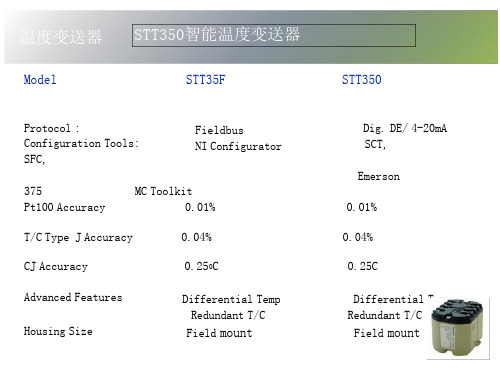
温度变送器 STT350智能温度变送器
Model
STT35F
Protocol : Configuration Tools: SFC,
Fieldbus NI Configurator
375 Pt100 Accuracy
Muracy CJ Accuracy
一体化温度变送器英文使用说明书

JWBIntegration temperaturetransmitter instructionsv3.0First summarizeJWB Integration temperature transmitter is a noncontact measuring temperature field with instrument ,Usually the related secondary instrument or computer data acquisition system supporting the use of the measurement ,It can accuratelymeasure the temperature of all kinds of medium and objects (used scope 200 ℃ ~ 1600 ℃) working process .The Principle of JWB Integration temperature transmitter is taking an amplifier transmission module into the waterproof or the critical terminal box of fabricated temperature sensor ,and connected with the sensor , output Standard 4 ~ 20 mA DC (two wire) .This series product were issued by the relevant national standards and regulations related GB JJG related content , and meet the relevant documents to IEC standard ,then finished by learning advantages of the reference of the same products abroad .It Makes the product more reliable, accurate, very suitable for all kinds of environment of the temperature measurement . Second technology parametersPower: 24 V DC (18 ~ 36 V DC) current output load: 500 Ω quartile (24 V DC) . Output: 4 ~ 20 mA .Precision: B level 0.5% (the module working in 10 ℃ ~ 70 ℃).nge: sighed in the product nameplate output protection: the sensor open, themaximum output of module must be less than 25 mA. Third wiring 、appearanceFourththe basic structure3.1 basic structure: sensor + (connection device + junction box + protection tube) +transmission module.3.2 Length: L = protection tube presidents × insert length (unit: mm, the seal facefollowing). 3.3 the length of the cold end.a. Transmission module working temperature between20 ℃ ~ 75 ℃.It makes t he temperature down between the temperature field and radiation by the cold end length ,Protecting the analog module circuit .b. If the thermocouple adopted , there must be cold end length .c. Protecting terminals and cable .d. The standard length of the cold end is 150 mm ,seeing the cold temperaturemeasurement environment influence situation can be appropriately changed , For example, below 125 ℃ temperature ,it should be 50 mm length or no cold end ,Higher temperature measurement ,The cold end length must be appropriately extended .Fifth installation5.1 Sensor can be insert into the temperature field center position.5.2 Generally, perpendicular installation is used in high temperature measuring, suchas side outfit will make protection pipe deformation damage, then protect the stent may be need.5.3 A strength tube maybe need in disturbance occasion, sensor is inserted into thepipe from strengthen monitoring site; As requiring the fast response time ,keep parts out .5.4 If the measurement of velocity places (such as pipe), not only the impact of the fluid,but also the damage of eddy should be considered.The structure strength of the tube must be good,and the installation method is also very important, such as flowing down the inclined installation, or in the pipeline turn orthogonal place tomeet insert installation.Related knowledge1,According to JJG national measurement standards, the temperature sensor must be inspected between 3 and 6 months once,and be replaced one year old. 2,Transmission modulemust be inspected and calibrated once between 6and 12 months. (the potentiometer Z [W1] the 4mA, G [W2] the 20 mA) 3,Selecting the product structure model carefully according to the work environment, because it relates the safety and life of product.4,Products which were designed by of the usingparty ,if there were problem of the quality and production party have nothing to do.Beijing Collihigh Sensor Techology Co,.Ltd.Address:8F,Tower C,ke shi builing,Armor 28,xinxi road,Haidian district Beijing China Postal code:100085 Tel:86-10-82671108 Fax:86-10-62533666。
试验设备常用的温度词语中英文对照
试验设备常用的温度词语中英文对照temperature rising,温升temperature scale,温(度)标(尺)temperature standard material for DTA,差热分析温度标准物质temperature standard material for TG,热重法温度标准物质temperature transducer (sensor),温度传感器temperature transmitter,温度变送器temperature uniformity,温度均匀性temporary base strain gauge,临时基底应变计tensile strength,拉伸强度tensile stress,拉应力tensile testing machine,拉力试验机tension force,张力terminal,终端terminal-based conformity,端基一致性terminal-based linearity,端基线性度terminal control,终端控制terminology standard,术语标准terrestrial radiation,地球辐射test block,试块test chamber,试验箱test coil,试验线圈test data,试验数据test for nominal samples,标样试验test for non-transmission(of an internal explosion),隔爆性能试验test frequency,激励频率;试验频率test loads,试验负荷test mass,试验质量test order,试验顺序test point,测试点test procedure standard,试验程序标准test signal,测试信号test solution,试验溶液test space,试验空间test surface,探伤面test table,工作台testability,可测试性tester,校验器testing bench,试台testing facility,试验装置testing system flexibility,试验系统的柔度texturometer,构造仪TG-DTA,热天平/差示热分析仪thematic mapper (TM),专题制图仪theodolite,经纬仪theorotical intensity of scattered ion,散射离子的理论强度theoretical slope factor,理论斜率因数thermal analysis,热分析thermal analysis curve,热分析曲线thermal analysis instrument,热分析仪器thermal analysis range,热分析范围thermal chemical gas analyzer,热化学式气体分析器thermal conductivity,热导率thermal conductivity cell,热导池thermal conductivity detector (TCD),热导检测器thermal conductivity gas analyzer,热导式气体分析器thermal conductivity gas transducer [sensor],热导式气体传感器thermal conductivity humidity transducer [sensor],热导式湿度传感器thermal conductivity meter,热导率计thermal conductivity of mixture gas,混合气体热导率thermal cone,温度锥thermal dilatometer,热膨胀仪thermal equilibrium,热平衡thermal fatigue testing machine,热疲劳试验机thermal hysteresis,热滞后thermal infrared range (TIR) remote sensing,热红外遥感thermal instrument,热系仪表thermal insulation,隔热thermal ionization mass spectrometer,热电离质谱计thermal magnetic oxygen analyzer,热磁式氧分析器thermal mass flowmeter,热式质量流量计thermal output,热输出thermal output coefficient,热输出系数thermal printer,热敏印刷机thermal radiation,热辐射(thermal)radiator,(热)辐射体thermal recorder,热式记录仪thermal response time,热响应时间thermal sensitivity drift,热灵敏度漂移thermal shock,热冲击shermal shock test chamber,热冲击试验箱thermal strain,热应变thermal stress,热应力thermal titration,热滴定(法)thermal wave electron image,热波电子象thermal wave electron microscope,热波电子显微镜thermal zero drift,热零点漂移thermistor,热敏电阻thermistor chain,热敏电阻测温链(thermo) reference material,(热)参比物thermo-sensitive element,热敏元件thermoacoustimetry,热(传)声法thermoacoustimetry apparatus,热传声仪thermobalance,热天平thermocouple,热电偶thermocouple circuit,热电偶电路thermocouple element,热电偶元件thermocouple instrument,热偶式仪表。
- 1、下载文档前请自行甄别文档内容的完整性,平台不提供额外的编辑、内容补充、找答案等附加服务。
- 2、"仅部分预览"的文档,不可在线预览部分如存在完整性等问题,可反馈申请退款(可完整预览的文档不适用该条件!)。
- 3、如文档侵犯您的权益,请联系客服反馈,我们会尽快为您处理(人工客服工作时间:9:00-18:30)。
TT302 温度变送器概述TT302温度变送器接收毫伏(mV)输出的信号,这类传感器包括热电偶或阻性传感器,例如:热电阻(RTD)。
它所接受的信号必须在允许的输入范围之内。
允许输入电压范围为-50到500,电阻范围为0到2000欧姆。
功能描述-硬件每个板的功能介绍如下:图2.1 TT302-硬件构成方框图多路转换器多路转换器将变送器端子接到相应信号调理板上,以保证在正确的端子上测量电压。
信号调理板他的作用给输入信号提供一个正确的值以满足A/D转换。
A/D转换器A/D转换器将输入信号转换成数字形式传给CPU。
信号隔离他的作用在输入和CPU之间隔离控制信号和数字信号。
中央处理单元(CPU)RAM PROM和EEPROMCPU是变送器的智能部分,主要完成测量,板的执行,自诊断和通信的管理和运行。
系统程序存储在PROM中。
RAM用于暂时存放运算数据。
在RAM中存放的数据一旦断电立即消失,所以数据必须保存在不易丢失的EEPROM中。
例如:标定,块的标识和组态等数据。
通信控制器监视在线动态,调整通信信号,插入,删除预处理,滤波。
电源变送器电路通过现场总线电源供电。
电源隔离像信号隔离一样,供给输入部分的信号必须要隔离,电源隔离采用变压器将直流供电电源转换成高频交流供电。
显示控制器从CPU接收数据送给LCD显示器的显示部分,此时显示器必须处于打开状态。
本机调整它有两个磁性驱动开关,它们必须由磁性工具来驱动而不是机械或电的接触。
图2.2-LCD指示器温度传感器TT302像前面所描述的那样,可以兼容多种类型的传感器。
TT302为使用热电偶或热电阻RTD 测量温度进行了特殊设计。
此类传感器的基本内容如下所述:热电偶热电偶由两种不同的金属或合金在一端连接在一起所组成的,被称为测量端或热端。
测量端必须放在测量点上,热电偶的另一端是打开的连接在温度变送器上,这一端称做参考端或冷端。
在大多数应用中,塞贝克效应可以充分解释热电偶的工作原理。
热电偶是如何工作的(塞贝克效应)当金属丝的两端有温差时,在金属丝的没一端都会产生一个小的电动势,这种现象就叫做塞贝克效应。
当两种不同金属丝连接在一起,而另一端开放时,两端之间的温差将会产生一个电压输出。
现在,有两个重要的问题需要注意:首先,热电偶所产生的电压与测量端和冷端的温度成比例,因此,为了得到被测温度必须加上参考端的温度,被称做冷端温度补偿。
TT302可以自动进行补偿。
为此,在TT302传感器端子装有一个温度传感器。
其次,如果热电偶与变送器端子之间的导线没有采用与热电偶相同的导线(例如:由热电偶传感器或接线盒到变送器端子之间采用铜线)那么就会对温度测量产生影响,因此必须要进行冷端补偿。
热电偶的电势在冷端温度为0℃时与热端温度的关系用热电偶分度表来表示。
分度表存储在TT302的存储器中,他们是国际标准NBS(B,E,J,K,N,R,S,T)和德国工业标准DIN(L,U) 热电阻(RTD)热电阻通常被称做RTD,它的工作原理是金属的阻抗会随着温度的升高而增加,存储在TT302的中的热电阻分度表有日本工业标准JIS[1604-81] (Pt50,Pt100)。
国际电工委员会IEC,DIN,JIS[1604-89] (Pt50,Pt100&Pt500),通用电气公司GE(Cu10)和DIN(Ni120)。
为使热电阻能够正确测量温度,必须消除传感器到测量电路之间线路电阻所造成的影响。
在一些工业应用中,这些导线有几百米长,在环境温度变化剧烈的场所,消除线路电阻的影响是极为重要的。
TT302允许二线制连接,但可能会引起测量误差。
此误差取决于接线的长度和导线经过处的温度(图2.3二线制连接)在二线制连接中,电压U2与热电阻的阻值R TD和导线的电阻R成正比U2=(R TD+2R X I图2.3二线制连接为了避免导线电阻的影响,推荐用三线制连接(图2.4三线制连接)或四线制连接(图2.5三线制连接)在三线制连接中,端子3是高阻抗输入端,因此,没有电流流过该导线,此导线上也没有压降。
电压U2-U1与电阻无关,因为导线电阻上的电压被抵消掉了,它仅与R TD的电阻有关。
U2-U1=(R TD+R)X I-RxI=R TDx I图2.4 三线制连接在四线制连接中,端子2和端子3是高阻抗输入端,因此,没有电流流过此端,也没有压降产生。
另外两根导线的电阻可不予考虑,这两根导线上也没有测量点,因此电压U2只与R TD电阻值有关U2=R TDx I图2.5四线制连接双通道连接和二线制连接相似,也存在相同的问题(图2.6双通道连接)导线的电阻需要测量,而且在同一温度下测量也不能忽略他们的阻值,因为长度也会影响使它们不同。
图2.6双通道连接西门子SIMATIC PCS 7 PS 展望投资成本低标准化的系统基于标准化的部件,因此有高度的挠性和可变性。
由于标准化技术的使用使其具有开放性运行和维护成本低全自动化具有电厂设备所需的控制系统的特殊功能和部件顾客利益与设备的适应性强可根据电厂的规模和特性进行扩展和改变可改变它的性能和记忆功能由一个服务器来实现从单一控制到分散控制具备电厂所需的特殊运行,监视,诊断和过程接口回顾自1997年投入市场截止到2002年8月100﹪的销售率在30多个国家投入使用控制领域:工业发电厂生物发电厂电厂单元机组的辅机成功的原因全自动化功率方案库的使用将SIMATIC PCS 7的兼容性增强创新性应用国际公认标准为控制和HMI提供一种开放系统服务范围无论何时何地都可得到全球范围内的服务经验在工程和节约时间方面提供高质量的规划,管理和方案技术认证过热器与再热器过热器是一种将热量传给饱和蒸汽以提高其温度的换热器。
蒸汽过热是中心电站所采用的设计特点之一,过热增加了整体循环效率。
另外,它降低了汽轮机末级叶片的湿度,因此提高了汽机的内在效率。
一般而言,过热器可分为辐射式过热器、对流式过热器或联合式过热器,这取决于热量是怎样从烟气传给蒸汽的。
这些过热器具有不同的运行特性,在机组负荷的宽范围内如能保持出口汽温不变,这样的特性是最希望的。
当出口汽温变得过高,则会引起过热器因部分过热而失效。
对流过热器位于炉膛出口,或能够从燃烧的高温产物吸收热能的区域。
对流过热器常常通过一束水冷管来遮蔽炉膛辐射热。
当这些管子留有足够的间隔时,也能遮断渣粒而减少过热器上的结渣问题。
在大型蒸汽发生器系统中,对流过热器常常分为两部分:一级过热器和二级过热器。
饱和蒸汽首先进入一级过热器而接受初始过热,一级过热器为于相对低的烟温区,在部分过热后,蒸汽进到二级过热器而完成其过热过程。
使过热器分为两级的主要原因是为蒸汽再热器提供一个空间,使烟气向蒸汽有效传热。
辐射过热器没有对流过热器那样得到普遍使用。
当需要辐射过热器时,它通常位于炉膛壁上代替一端水冷管。
另一种布置是使辐射过热器刚好在屏式管后面,辐射过热器是二级过热器的中间部分。
中心电站锅炉提供蒸汽再热。
再热器一般是对流式,且通常位于一级与二级过热器之间的空间。
当蒸汽温度在汽机中部分膨胀后,它返回锅炉再热。
离开再热器的蒸汽温度通常等于过热蒸汽温度。
因为再热器的设计在运行本质上与过热器一样,过热器的讨论将同样适用于再热器。
在过热器的热力设计中,首先确定蒸汽温度。
一般而言这点在电站系统设计中完成,以平衡电站初始费用和服役期运行费用。
近年来,对于所有蒸汽发生器系统,最佳蒸汽温度约538℃。
热力设计中的第二步是近似确定所要求的过热器面积数量。
在过热器表面积被确定后,下一步要考虑的是选择管子的长度、管径和管子数。
显然,选择是一个反复的过程,先产生一个尝试解,查看其各种约束是否满足,从各种可接受解中找到最优解。
最佳过热器应该有给予设计汽温所必需的足够的传热表面。
管子参数(长度和直径)使得蒸汽压降和管子金属温度将不超过设计值。
管子金属温度是一个重要参数,对管子材料的选择有很大影响。
另外,最佳过热器要使管子布置得使所产生的灰和渣最少。
现代过热器有许多管子通道,管子都顺排布置而不用错排布置。
管子通常是圆管,外径为5或6.3cm。
没有附在管子上的扩展表面(如肋片),材料的选择取决于蒸汽温度和压力。
碳钢的允许温度达430℃,常常用于低温过热器。
铬-钼钢、不锈钢或某种类似的耐热合金能承受高达650℃的温度,因而它们被选做高温区过热器。
温度调节与控制对过热器与再热器都很重要,蒸汽温度调节常常要在锅炉指定的时间内进行,原则方法是增加或减少传热面积。
蒸汽温度也可以通过调节热烟气温度和质量流量来实现。
一般而言,这些都是通过改变过量空气或者蒸发段效果来完成。
在锅炉运行中,有许多因素影响离开过热器和再热器的蒸汽温度,它们包括锅炉负荷、过量空气、给水温度和受热面的清洁度。
运行中蒸汽温度的控制必须在不改变设备布置的情况下完成,最有效的措施包括:烟气旁路,燃烧器控制,温度调节,烟气再循环,过量空气以及分隔炉膛。
烟气旁路是控制烟气流过过热器的流量,这种方法是主要缺点是高温区可动闸板操作运行困难,且对负荷变化响应慢。
燃烧器控制通常是控制火焰位置和燃烧速度,使燃烧器倾斜可以使火焰指向或离开过热器,这将改变炉膛的吸热和过热器的烟气温度。
随着锅炉负荷减小,燃烧器将逐一推出运行,这将改变燃烧速度,从而改变流经过热器的烟气流量。
温度调节是常使用的方法之一,温度调节器通常位于一级和二级过热器之间。
有两种基本形式的温度调节器:一种是管式,一部分过热蒸汽通过换热器管道,将热量传给锅炉水(可以是锅炉给水或锅炉汽包水),随后进入温度调节,从一级过热器分开的蒸汽将会合,一起进入二级过热器;第二种温度调节器是将给水喷入过热蒸汽流中。
给水蒸发使蒸汽温度降低,控制给水量就可以控制蒸汽温度。
必须注意要使喷水足够纯净,喷水要和过热蒸汽很好地混合,从而使得第二级过热器的入口没有水滴。
烟气再循环通常采用改变炉膛和过热器的吸收率来控制蒸汽温度,当需要蒸汽温度声高时,从省煤器出口取出的一部分烟气将循环返回炉膛底部。
因此,炉膛温度降低,导致炉膛吸热减少,而炉膛出口烟温升高。
这么高的烟温,加上烟气流量增加,将增加过热器的传热速率,使蒸汽出口温度升高。
温度控制也受所使用的过量空气量的影响,过量空气越多,蒸汽出口温度将越高,其原因与烟气再循环方法的原因类似。
必须指出,太多的过量空气将导致锅炉燃烧效率降低。
分隔炉膛锅炉是将饱和蒸汽的生产安排在一段,而将过热蒸汽的生产安排在另一段。
过热汽温是通过控制两个炉膛中的燃烧速率来调节的,这一方法不经济,很少应用中心电站锅炉。
译文:TT302—Field bus Temperature TransmitterOperationThe TT302 accepts signals from mV generators such as thermocouples or resistive sensors such asRTDs. The criterion is that the signal is within the range of the input. For mV, the range is -50 to 500mV and for resistance, 0-2000 Ohm.Functional Description – HardwareThe function of each block is described below.Figure 2.1—TT302Block DiagramMUX MultiplexerThe MUX multiplexes the sensor terminals to the signal conditioning section ensuring that the voltages are measured between the correct terminals.Signal ConditionerIts function is to apply the correct gain to the input signals to make them suit the A/D -converter. A/D ConverterThe A/D converts the input signal to a digital format for the CPU.Signal IsolationIts function is to isolate the control and data signal between the input and the CPU.(CPU) Central Processing Unit, RAM, PROM and EEPROMThe CPU is the intelligent portion of the transmitter, being responsible for the management and operation of measurement, block execution, self-diagnostics and communication. The program is stored in a PROM. For temporary storage of data there is a RAM. The data in the RAM is lost if the power is switched off. However there is a nonvolatile EEPROM where data that must be retained is stored. Examples, of such data are trim, calibration, block configuration andidentification data.TT302 - Fieldbus Temperature TransmitterCommunication ControllerIt monitors line activity, modulates and demodulates communication signals and inserts and deletes start and end delimiters.Power SupplyTakes power of the loop-line to power the transmitter circuitry.Power IsolationJust like the signals to and from the input section, the power to the input section must be isolated. Isolation is achieved by converting the DC supply into a high frequency AC supply and galvanically separating it using a transformer.Display ControllerReceives data from the CPU informing which segments of the Liquid Crystal Display, should be turned on.Local AdjustmentThere are two switches that are magnetically activated. They can be activated by the magnetic tool without mechanical or electrical contact.Figure 2.2 - LCD IndicatorTemperature SensorsThe TT302, as previously explained, accepts several types of sensors. The TT302 is specially designed for temperature measurement using thermocouples or Resistive Temperature Detectors (RTDs).Some basic concepts about these sensors are presented below.ThermocouplesThermocouples are constructed with two wires made from different metals or alloys joined at one end, called measuring junction or "hot junction". The measuring junction should be placed at the point of measurement. The other end of the thermocouple is open and connected to the temperaturetransmitter. This point is called reference junction or cold junction.For most applications, the Seebeck effect is sufficient to explain thermocouple behavior as following:How the Thermocouple Works (Seebeck Effect)When there is a temperature difference along a metal wire, a small electric potential, unique to every alloy, will occur. This phenomenon is called Seebeck effect. When two wires of dissimilar metals are joined at one end, and left open at the other, a temperature difference between the two ends will result in a voltage since the potentials generated by the dissimilar materials are different and do not cancel each other out. Now, two important things must be noted. First: the voltage generated by the thermocouple is proportional to the difference between the measuring-junction and the cold junction temperatures. Therefore the temperature at the reference junction must be added to the temperature derived from the thermocouple output, in order to find the temperature measured. This is called cold junction compensation, and is done automatically by the TT302, which has a temperature sensor at the sensor terminals for this purpose. Secondly, if the thermocouple wires are not used, all the way to the terminals of the transmitter (e.g., copper wire is used from sensor-head or marshaling box) will form new junctions with additional Seebeck effects. It will be created and ruin the measurement in most cases, since the cold-junction compensation will be done at the wrong point.NOTEThe relation between the measuring junction temperature and the generated mili-voltage is tabulated in thermocouple calibration tables for standardized thermocouple types, the reference temperature being 0 oC.Standardized thermocouples that are commercially used, whose tables are stored in the memory of the TT302, are the following:. NBS (B, E, J, K, N, R, S & T). DIN (L & U)Resistive Temperature Detectors (RTDs)Resistance Temperature Detectors, most commonly known as RTD’s, are based on the principle that the resistance of metal increases as its temperature increases. Standardized RTDs, whose tables are stored in the memory of the TT302, are the following:. JIS [1604-81] (Pt50 & Pt100). IEC, DIN, JIS [1604-89] (Pt50, Pt100 & Pt500).. GE (Cu10).. DIN (Ni120)For correct measurement of RTD temperature, it is necessary to eliminate the effect of the resistance of the wires connecting the sensor to the measuring circuit. In some industrial applications, these wires may be hundreds of meters long. This is particularly important at locations where the ambient temperature changes constantly.The TT302 permits a 2-wire connection that may cause measuring errors, depending on the length of connection wires and on the temperature to which they are exposed. (See Figure 2.3 -Two-Wire Connection).In a 2-wire connection, the voltage V2 is proportional to the RTD resistance plus the resistance of the wires.V2 = [RTD + 2 x R] x IFigure 2.3 - Two-Wire ConnectionIn order to avoid the resistance effect of the connection wires, it is recommended to use a 3-wire connection (See Figure 2.4 – Three-Wire Connection) or a 4-wire connection (See Figure 2.5 - Four - Wire Connection).In a 3-wire connection, terminal 3 is a high impedance input. Thus, no current flows through that wire and no voltage drop is caused. The voltage V2-V1 is independent of the wire resistances since they will be cancelled, and is directly proportional to the RTD resistance alone.V2-V1 =[RTD + R] x I - R x I = R TD x IFigure 2.4 - Three – Wire ConnectionIn a 4-wire connection, terminals 2 and 3 are high impedance inputs. Thus, no current flows through those wires and no voltage drop is caused. The resistance of the other two wires is not of interest, since there is no measurement registered on them. Hence the voltage V2 is directly proportional to the RTD resistance.(V2 = RTD x I)Figure 2.5 - Four - Wire ConnectionA differential or dual channel connection is similar to the two-wire connection and gives the same problem (See Figure 2.6 - Differential or Dual Connection). The resistance of the wires will be measured and do not cancel each other out in a temperature measurement, since linearization will affect them differently.Figure 2.6 - Differential or Dual ConnectionSIEMENSHighlight of SIMATIC PCS 7 PSLow investment costs.Modular system based on standard components, therefore high degree of flexibility and scalability..Open thanks to the use of standard technologies.Low operation and maintenance costs.Horizontal integration with Totally Integrated Au tomation..Control system specific functionality and components for power plant requirements. Customer Profits.Optimum adaptation to the requirements..Expansion and adaptations according to size and plant characteristic. .Scalable performances and memories for control..Scalable from single station to distributed control system with client-server architecture..Power-plant-specific operation and monitoring,diagnostics and process interface.Facts& Figures of Simatic PCS7 PSThe Scope.On the market since 1997..100 sold to date (as of 08/2002)..In use in more than 30 countries..In control of:Industrial power plantsBiomass power plantsAuxiliaries of power plantsReasons behind this success.Totally Integrated Au tomation:Consistent use of SIMATIC PCS7 with Power Solution Library.Innovation Nature:We provide an open system using international recognized standards for control and HMI.Competence:Worldwide services which are available for you anytime, anywhere! .Experience:Project management and process know-how guarantee for high quality in project engineering and saving time.Superheater and ReheaterThe superheater is a heat exchanger in which heat is transferred to the saturated steam to increase its temperature. Stream superheating is one of the design features accepted in central electric power stations. Superheating raise overall cycle efficiency. In addition, it reduces a moisture level in the last stages of the steam turbine and thus increases the turbine internal efficiency.Superheaters are commonly classified as either radiant superheaters, convective superheaters, or combined superheaters, depending on how heat id transferred from the gases to steam. These superheaters have different performance characteristics. The feature that the outlet steam temperature can stay essentially constant over a wide range of unit load is the most desirable. When the outlet steam temperature becomes excessive, it may cause failures from overheating parts of the superheater.The convective superheater is located in the furnace exit or in the zone where it can receive thermal energy from the high temperature produces of combustion. The convective superheater is frequently screened from the furnace radiation by a bank of water-filled tubes. These tubes, when adequately spaced, can also intercept the slag particle and reduce slagging problems in superheatrs. Convective superheaters in large steam generator systems are frequently split into two parts: the primary superheater and the secondary superheaater. Saturated steam first enters the primary superheater and receives the initial heating. The primary superheater is located in a zone of relatively low gas temperature. After the partial heating steam moves to the secondary superheater and completes its superheaing process. The main reasons for splitting the superheater are to provide space for the steam reheater and to achieve an effective heat transfer from the gases the steam.The radiant superheater is not as commonly used as the convective superheater. When the radiant superheater is needed, it is usually placed on the furnace wall replacing a section of water-filled tubes. Another arrangement is to have the radiant superheater just behind the screen tubes. The radiant superheater is an integral part of the secondary superheater.Central station boilers provide for steam reheating. The reheater is essentially a convective type and usually located in the space between thee primary and secondary superheaters. After steam partially expands in the tubine, it returns to the boiler for reheating. The temperature of steam leaving the reheater is usually equal to the superheated steam temperature. Since the design and operation of reheater are essentially the same as superheaters, the discussion of superheaters will be equally applicable to reheaters.In superheater thermal design, the steam temperature is first determined. This is generally accomplished in the plant system design, balancing the plant initial cost against the lifttime operating cost. In recent years the optimum steam temperature is approximately 538℃ for all large steam generation systems. In the second step, the amount of superheater surface required is approximated.After the amount of superheater surface id determined, the next consideration is to select the tube length, tube diameter, and the number of tubes. Evidently, the selection is an iterative process, generating a trial solution and checking to see whether all constraints are met. From several acceptable solutions, the optimum is found. The optimum superheater should have enough heat transfer surface necessary to give the design steam temperature. The tube parameters(length and diameter) are such that the steam pressure drop and tube metal temperature willnot exceed the design values. The tube metal temperature is an important parameter and has a strong influence on the tube material selection. In addition, the optimum superheater should have its tubes so spaced that minimum ash and slag deposits will result.Modern superheaters have many tube passes, and the tubes are arranged in-line rather than staggered. The tubes are usually cylindrical and have 5 or 6.3cm outside diameter. There is no extended surface(i.e.fins)attached to the tubes. The material selection depends on the steam temperature and pressure. Carbon steel has an allowable temperature up to 430℃ and is frequently used for loe-temperature superheaters. Chrome-moly, stainless steel, or same similar heat resistant alloy can withstand the temperature up to 650℃. Therefore they are selected for the Superheater in a high-temperature zone.Temperature regulation and control are importation for both superheaters and reheaters. Steam temperature adjustments are frequently made at the time of the commissioning of a boiler. The principal methods are an addition or regulating the hot gas temperature and mass flow rate. These are generally accomplished by changing the excess air or the effectiveness of the evaporation section.During a boiler operation, there are many factors affecting the temperature of steam leaving the superheater and reheater. These include a boiler load, excess air, feedwater temperature, and cleanliness of heating surfaces. Control of steam temperature during operation must be done without changing the arrangement of equipment. The most effective approaches are gas bypass, burner control, attemperation, gas recirculation, excess air, divided furnace.A gas bypass is to control the gas flow rate to superheater. The main disadvantages of this approach are the operating difficulties experienced by the movable dampers located in the high-temperature zone and the slow response to load change.Burner control is used to control the flame location and combustion rate. Tilting burners can direct the flame toward or away from the superheater. These will result in a change of heat absorption in the furnace and change of gas temperature in the superheater. As the boiler load is reduced, burners are removed one by one from service. This will change the combustion rate and, thus, change the gas flow rate to the superheater.Attemperation is one of approaches frequently used. The attemperator is usually located at the point between the primary and secondary superheaters.There are two basic types of attemperator. The first is the tubular type in which some of superheated steam is passed through the tubes of a heat exchanger and has heat transferred to the boiler water(either boiler feedwater or water in the boiler drum).Subsequent to attemperation, the divided streams from the primary superheater will combine and enter the secondary superheater.The second type of attemperator involves a spray of feedwater into the atream ofsuperheated steam. The feedwater evaporates and reduces the steam temperature. Controlling the amount of feedwater will result in control of the ateam temperature. Care must be exercised to ensure that the spray water has sufficient purity. Thespray water should mix well with the superheated steam so that there are no water droplets in the inlet of the secondary superjeater.Gas recirculation is used to control the steam temperature by changing the heat absorption rates both in the furnace and in the superheater. When the ateam temperature needs to be raised, some of the furnace. Therefore, the furnace temperature will become lower, resulting in a lower heat absorption in the furnace and thereby a higher flue gas temperature in the furnace exit. This high gas temperature, combined with an increase in the gas floe rate, will increase the heat transfer rate in the superheater and thus increase the steam outlet temperature.Temperature control can be affected bu using different amounts of excess air. the more the excess air, the higher the steam outlet temperature would be. The reasons for this are similar to those for the gas recirculation method. It must be pointed out, however, that too much excess air will result in a reduction of boiler combustion efficiency. A divided-furnace boiler is usually arranged with a generation of saturated steam in one section and a superheating of steam in another section. The temperature of the superheated steam is regulated by controlling the firing rates in the two furnaces. This method is not economical and is seldom applied in a central electric power station.。