模糊控制外文文献
模糊控制的移动机器人的外文翻译.doc

1998年的IEEE国际会议上机器人及自动化Leuven ,比利时1998年5月一种实用的办法--带拖车移动机器人的反馈控制F. Lamiraux and J.P. Laumond拉斯,法国国家科学研究中心法国图卢兹{florent ,jpl}@laas.fr摘要本文提出了一种有效的方法来控制带拖车移动机器人。
轨迹跟踪和路径跟踪这两个问题已经得到解决。
接下来的问题是解决迭代轨迹跟踪。
并且把扰动考虑到路径跟踪内。
移动机器人Hilare的实验结果说明了我们方法的有效性。
1引言过去的8年,人们对非完整系统的运动控制做了大量的工作。
布洛基[2]提出了关于这种系统的一项具有挑战性的任务,配置的稳定性,证明它不能由一个简单的连续状态反馈。
作为替代办法随时间变化的反馈[10,4,11,13,14,15,18]或间断反馈[3]也随之被提出。
从[5] 移动机器人的运动控制的一项调查可以看到。
另一方面,非完整系统的轨迹跟踪不符合布洛基的条件,从而使其这一个任务更为轻松。
许多著作也已经给出了移动机器人的特殊情况的这一问题[6,7,8,12,16]。
所有这些控制律都是工作在相同的假设下:系统的演变是完全已知和没有扰动使得系统偏离其轨迹。
很少有文章在处理移动机器人的控制时考虑到扰动的运动学方程。
但是[1]提出了一种有关稳定汽车的配置,有效的矢量控制扰动领域,并且建立在迭代轨迹跟踪的基础上。
存在的障碍使得达到规定路径的任务变得更加困难,因此在执行任务的任何动作之前都需要有一个路径规划。
在本文中,我们在迭代轨迹跟踪的基础上提出了一个健全的方案,使得带拖车的机器人按照规定路径行走。
该轨迹计算由规划的议案所描述[17] ,从而避免已经提交了输入的障碍物。
在下面,我们将不会给出任何有关规划的发展,我们提及这个参考的细节。
而且,我们认为,在某一特定轨迹的执行屈服于扰动。
我们选择的这些扰动模型是非常简单,非常一般。
它存在一些共同点[1]。
毕业设计(论文)-基于模糊理论与常规的模糊pid控制方法研究[管理资料]
![毕业设计(论文)-基于模糊理论与常规的模糊pid控制方法研究[管理资料]](https://img.taocdn.com/s3/m/d0099326b14e852459fb57c8.png)
基与模糊理论与常规的模糊PID控制方法研究Research on fuzzy PID control method based on fuzzy theory and fuzzy theory学生姓名:指导教师:摘要传统PID控制是经典控制理论中的一种比例微分积分控制,是工业中应用最广泛的控制方法。
但是随着社会和生产的发展,对自动控制的响应速度,系统稳定性和适应能力有了更高的要求。
经典控制要求被控对象具有确定的,线性化的数学模型,但是具体实际被控对象都不同程度存在非线性,建模困难的特点,于是模糊控制由此产生。
模糊控制技术是近代智能控制理论的新颖技术,通过模拟人的近似推理和判断过程,是控制算法的可控性、适应性和合理性提高。
模糊控制的优点,如能有效减小系统超调量,提高系统的响应速度,缩短系统的调节时间,总体来说,大大增强了控制系统的动态性能。
模糊控制作为一种相对较新的控制方法,它也能提供更多的发展空间。
所选期刊给出了PID控制器、模糊控制器、自适应PID模糊控制的基本原理和设计方法,通过仿真比较,得出了PID模糊控制比前两者具有更好的系统动态性能,控制品质指标优于传统PID以及模糊控制。
关键词:模糊控制;PID控制;模糊PID控制AbstractThe traditional PID control is a classic control integral proportional differential control theory, control method is the most widely used in industry. But with the development of society and production, theresponse speed、stability and adaptabilityof the automatic control system have been requiring hight increasingly. The classical control requirements of the controlled object is determined mathematical model linear, but the actual controlled object are nonlinear characteristics, difficulties in modeling, and fuzzy control. The resulting fuzzy control technology is a modern novel intelligent control technology theory, the approximate reasoning and judgment process simulation of the people, is the controllability of control algorithm, improve the adaptability and rationality. The advantages of fuzzy control such as, can effectively reduce the overshoot and improve the response speed of the system, shorten the adjustment time, overall, greatly enhancing the dynamic control system As a relatively new control method, fuzzy control can also provide more room for development.Selected journals gives the PID controller, fuzzy controller, fuzzy adaptive PID control basic principle and design method of, by simulation and comparison, it is concluded that the PID fuzzy control has better dynamic performance than the previous two, quality index is better than the traditional PID control and fuzzy control.Key words: Fuzzy control; PID control; Fuzzy PID control目录摘要 (Ⅰ)Abstract (Ⅱ)第一章绪论 (1) (1) (1) (2)第二章PID控制基本原理 (2) (2) (4) (4) (6)第三章模糊PID控制器设计 (7)模糊逻辑控制过程 (7) (9) (10).................................................. (11)................................................ (11)模糊逻辑推理................................................ ..12 (18)第四章系统的仿真 (19) (19) (20)结束语 (26)参考文献...............................................,,27附录.. (28)第一章绪论问题的提出20世纪中叶以来,在科学技术与工业发展过程中,自动控制理论与技术发挥了巨大的作用,并取得了巨大的成就,是现代高新技术的重要手段之一。
洗衣机模糊控制
故障等.
4) 研制样机的洗净率、各项传感特性、各种模
糊输出量、各种洗涤功能均达到了我国相关的标准
和合同约定的技术要求.
5) 经连续运转和施加强电磁干扰,证明系统
健壮性好、抗干扰能力强.
6) 实现模糊控制后,样机节水12%~18%,
节电7%~12%.节水、节电、省时效果良好.
门狗”技术等方面加强研究和实施.着重防止程序
“跑飞”,并解决好系统非法复位的自恢复问题,使系
统具有故障诊断功能.
2.4 其他技术框架
2.4.1 实验分析与模糊规则的建立 洗衣机的洗
涤过程包括初洗、主洗、过清、处理等工艺程序.洗
涤的全过程为3输入5输出的控制过程,输入量为
布质、布量、脏污程度和脏污性质;输出量为水位、转
术框架
本系统是一个多输入多输出的控制系统.主要
输入量(模糊量)有洗涤物的布质、布量、脏污程度、
脏污性质等.系统的输出量有电机转速、进水量、水
位、洗涤时间(包括过清和脱水时间)和洗涤剂投放
量等.总的设计思路是利用相应的传感器检测各种
输入量,通过转换和处理,运用各种控制模块和模糊
控制规则,经模糊计算和推理决策,确定洗涤程序和
洗涤过程中的输出量.
2.1 模糊控制器设计的框架构思
模糊控制器设计利用主要因素推理和间接推理
等方法.主要因素推理即是抓住主要因果关系,放
弃次要因果关系.例如,用布质、布量的监测数据来
推理决策水位、转速、洗涤时间等工作参数.间接推
理亦称顺序推理,即将前一种推理作为本次推理的
前提,从而引申出新的结果.例如,若洗涤剂投放量
机以更强大的生命力.系统的研制开发是以XGQ-
模糊控制器设计外文资料翻译
外文资料翻译Static Output Feedback Control for Discrete-time Fuzzy Bilinear System Abstract The paper addressed the problem of designing fuzzy static output feedback controller for T-S discrete-time fuzzy bilinear system (DFBS). Based on parallel distribute compensation method, some sufficient conditions are derived to guarantee the stability of the overall fuzzy system. The stabilization conditions are further formulated into linear matrix inequality (LMI) so that the desired controller can be easily obtained by using the Matlab LMI toolbox. In comparison with the existing results, the drawbacks such as coordinate transformation, same output matrices have been eliminated. Finally, a simulation example shows that the approach is effective.Keywords discrete-time fuzzy bilinear system (DFBS); static output feedback control; fuzzy control; linear matrix inequality (LMI)1 IntroductionIt is well known that T-S fuzzy model is an effective tool for control of nonlinear systems where the nonlinear model is approximated by a set of linear local models connected by IF-THEN rules. Based on T-S model, a great number of results have been obtained on concerning analysis and controller design[1]-[11]. Most of the above results are designed based on either state feedback control or observer-basedcontrol[1]-[7].Very few results deal with fuzzy output feedback[8]-[11]. The scheme of static output feedback control is very important and must be used when the system states are not completely available for feedback. The static output feedback control for fuzzy systems with time-delay was addressed [9][10] and a robust H∞ controller via static output feedback was designed[11]. But the derived conditions are not solvable by the convex programming technique since they are bilinear matrix inequality problems. Moreover, it is noted that all of the aforementioned fuzzy systems were based on the T-S fuzzy model with linear rule consequence.Bilinear systems exist between nonlinear and linear systems, which provide much better approximation of the original nonlinear systems than the linear systems [12].The research of bilinear systems has been paid a lot of attention and a series of results have been obtained[12][13].Considering the advantages of bilinear systems and fuzzy control, the fuzzy bilinear system (FBS) based on the T-S fuzzy model with bilinear rule consequence was attracted the interest of researchers[14]-[16]. The paper [14] studied the robust stabilization for the FBS, then the result was extended to the FBS with time-delay[15]. The problem of robust stabilization for discrete-time FBS (DFBS) was considered[16]. But all the above results are obtained via state feedback controller.In this paper, a new approach for designing a fuzzy static output feedback controller for theDFBS is proposed. Some sufficient conditions for synthesis of fuzzy static outputfeedback controller are derived in terms of linear matrix inequality (LMI) and the controller can be obtained by solving a set of LMIs. In comparison with the existing literatures, the drawbacks such as coordinate transformation and same output matrices have been eliminated.Notation: In this paper, a real symmetric matrix 0P > denotes P being a positive definite matrix. In symmetric block matrices, an asterisk (*) is used to represent a symmetric term and {...}diag stands for a block-diagonal matrix. The notion ,,1si j l =∑means 111s s si j l ===∑∑∑. 2 Problem formulationsConsider a DFBS that is represented by T-S fuzzy bilinear model. The i th rule of the DFBS is represented by the following form11 ()...() (1)()()()()()()1,2,...,i i v vi i i i i R if t is M and and t is M then x t A x t B u t N x t u t y t C x t i sξξ+=++== (1)Where iR denotes the fuzzy inference rule, s is the number of fuzzy rules.,1,2...ji M j v=is fuzzy set and()j t ξis premise variable.()nx t R ∈Is the statevector,()u t R ∈is the control input and T 12()[(),(),..,()]q q y t y t y t y t R =∈ is the system output. The matrices ,,,i i i i A B N C are known matrices with appropriate dimensions. Since the static output feedback control is considered in this paper, we simply set v q =and11()(),...,()()v q t y t t y t ξξ==.By using singleton fuzzifier, product inference and center-average defuzzifier,the fuzzy model(1) Can be expressed by the following global model11(1)(())[()()()()]()(())()si i i i i si i i x t h y t A x t B u t N x t u t y t h y t C x t ==+=++=∑∑(2)Where 11(())(())/(()),(())(())qsi i i i ij i j h y t y t y t y t y t ωωωμ====∑∏.(())ij y t μisthegradeofMembership of()j y t injiM . We assumethat (())0i y t ω≥and 1(())0si i y t ω=>∑. Then we have the followingconditions:1(())0,(())1si i i h y t h y t =≥=∑.Based on parallel distribute compensation, the fuzzy controller shares the same premise parts with (1); that is, the static output controller for fuzzy rule i is written as11T T ()... () ()()/1i i v vii i i R if y t is M and and y t is M then u t F y t y F F yρ=+(3)Hence, the overall fuzzy control law can be represented as111()()sin cos ()1ss si i i i i i i i i i T T i i F y t u t h h h F y t y F F yρρθρθ======+∑∑∑ (4)WhereT T T T ()1sin ,cos ,[,],1,2,...,2211i i i i i i i i F y t i sy F F yy F F y ππθθθ==∈-=++.1q i F R ⨯∈is a vector to be determined and 0ρ>is a scalar to be assigned.By substituting (4) into (2), the closed-loop fuzzy systems can be represented as,,11(1)()()()si j l ijl i j l si i i x t h h h x t y t h C x t ==+=Λ=∑∑ (5)wherecos sin ijl i i j l j i jA B F C N ρθρθΛ=++.The objective of this paper is to design fuzzy controller (4) such that the DFBS(5) is asymptotically stable. 3 Main resultsNow we introduce the following Lemma which will be used in our main results.Lemma 1 Given any matrices ,M N and 0P >with appropriate dimensions suchthat 0ε>, the inequality T T T 1TM PN N PM M PM N PN εε-+≤+holds.Proof: Note that 11112222()()()()T TTTM PN N PM P M P N P N P M +=+Applying Lemma 1 in [1]: 1T T T TM N N M M M N N εε-+≤+, the inequalityT T T 1T M PN N PM M PM N PN εε-+≤+can be obtained. Thus the proof iscompleted.Theorem 1 For given scalar 0ρ>and 0,,1,2,...,ij i j sε>=, the DFBS (5) isasymptotically stable in the large, if there exist matrices 0Q >and ,1,2,...,i F i s = satisfying the inequality (6).T T T 111()0000 ,,1,2,...,i i i j l ijl Q QA QN B F C Q a Q b Q b Q i j l s ---⎡⎤-⎢⎥*-⎢⎥Φ=<⎢⎥**-⎢⎥***-⎣⎦= (6)Where211,(1)ij ij a b ερε-=+=+.Proof: Consider the Lyapunov function candidate asT ()()()V t x t Px t =(7)where 1P Q -= is to be selected.Define the difference ()(1)()V t V t V t ∆=+-, and then along the solution of (5), we haveT TT ,,1,,1T T T T 12,,1,,1T T T ,,1()()()()()()()()()() ()()()ssi j l m n p ijl mnp i j l m n p ssi j l m n p ijl mnp ijl mnp i j l m n p s i j l ijl ijl i j l V t h h h h h h x t P x t x t Px t h h h h h h x t P P x t x t Px t h h h x t P x t x t P =====∆=ΛΛ-=ΛΛ+ΛΛ-≤ΛΛ-∑∑∑∑∑()x t (8)Applying Lemma 1 again, it follows thatT T T 21T T (cos sin )(cos sin ) (1)(1)[()()]ijl ijl i i j l j i j i i j l j i j ij i i ij i j l i j l i i P A B F C N P A B F C N A PA B F C P B F C N PN ρθρθρθρθερε-ΛΛ=++++≤++++(9)Substituting (9) into (8) leads toT T T T ,,1()()[()()]()si j l i i i j l i j l i i i j l V t h h h x t aA PA b B F C P B F C bN PN P x t =∆≤++-∑ (10)Applying the Schur complement, (6) is equivalent toT 1T 1T 1()(Q)0i i i j l i j l i i Q aQA Q A Q b B F C Q Q B F C bQN Q N Q ----+++< (11)Pre- and post multiplying both side of (11) with P , respectively, we haveT T T ()()0i i i j l i j l i i P aA PA b B F C P B F C bN PN -+++< (12)Therefore, it is noted that ()0V t ∆<, then the DFBS (5) is asymptotically stable. Thus the proof is completed.The matrix inequality (6) leads to BMI optimization, a non-convex programming problem. In the following theorem, we will derive a sufficient condition such that thematrix inequality (6) can be transformed into an LMI problem.Theorem 2 For given scalar 0ρ>and 0,,1,2,...,ij i j sε>=, the DFBS (5) isasymptotically stable in the large, if there exist matrices 0Q >and ,1,2,...,i F i s = satisfying the inequality (13).T T T 1110()000000 ,,1,2,...,i i l ijl i j Q QA QN C Q a Q I b Q I b Q B F I i j l s ---⎡⎤-⎢⎥*-+⎢⎥⎢⎥ψ=<**-+⎢⎥***-⎢⎥⎢⎥****-⎣⎦= (13)Proof: It is trivial thatT T ()()00000()()l l ijl i j i j C Q C Q I I B F B F φ⎡⎤⎢⎥*⎢⎥=>⎢⎥**⎢⎥***⎢⎥⎣⎦(14)Then ifijl ijl φΦ+<, we can conclude thatijl Φ<.TT T T 11T 1T TT 111()()00()000000()()()0000 00l l i i i j l ijl ijl i j i j l i i i j C Q C Q Q QA QN B F C Q I a Q I b Q B F B F b Q C Q Q QA QN a Q Ib Q IB F b Q φ------⎡⎤⎡⎤-⎢⎥⎢⎥**-⎢⎥⎢⎥Φ+=+⎢⎥⎢⎥****-⎢⎥⎢⎥******-⎢⎥⎣⎦⎣⎦⎡⎡⎤-⎢⎢⎥*-+⎢⎢⎥=+⎢⎥**-+⎢⎥***-⎣⎦⎣T00()l i j C Q B F ⎤⎥⎥⎡⎤⎣⎦⎢⎥⎢⎥⎢⎥⎦(15) By applying Schur complement, (13) is equivalent toijl ijl φΦ+<. Then wegetijl Φ<. According to Theorem 1, the DFBS (5) is asymptotically stable. Thus theproof is completed.4 Numerical examplesIn this section, an example is used for illustration. The considered DFBS is1: (1)()()()()()() 1,2i ii i i i R ify is M then x t A x t B u t N x t u t y t C x t i +=++==Where1212129.78-1010101,,,510510011A A N N B B ----⎡⎤⎡⎤⎡⎤⎡⎤======⎢⎥⎢⎥⎢⎥⎢⎥---⎣⎦⎣⎦⎣⎦⎣⎦ [][]1210,10.C C ==-The membership functions are defined as111()(1cos())/2,M y y μ=-2111()1()M M y y μμ=-.By letting 111221220.72,0.2, 1.51,ρεεεε===== applying Theorem 2 and solving the corresponding LMIs, we can obtain the following solutions:[][]12-1.5014,11.0790 2.2785,-3.0452.2.27850.5984F Q F =⎡⎤=⎢⎥=⎣⎦ Simulation results with the initial conditions:[]T1.4-1.6 respective, areshown in Fig.1 and Fig.2. One can find that all these state converge to the equilibrium state after 17 seconds.2468101214161820-2-1.5-1-0.500.511.5tx (t )x 1x 202468101214161820-0.6-0.4-0.20.20.40.60.8tu (t )Fig.1. State responses of system Fig.2. Control trajectory of system 5 ConclusionsIn this paper, a new and simple approach for designing a fuzzy static output feedback controller for the discrete-time fuzzy bilinear system is presented. The result is formulated in terms of a set of LMI-based conditions. By the proposed approach, the local output matrices are not necessary to be the same. Thus, the constraints had been relaxed and applicability of the static output feedback is increased.References[1] Wang R J, Lin W W and Wang W J. Stabilizability of linear quadratic state feedback for uncertain fuzzy time-delay systems [J]. IEEE Trans. Syst., Man, and Cybe., 2004, 34(2):1288-1292.[2] Cao Y Y and Frank P M. Analysis and synthesis of nonlinear time-delaysystems via fuzzy control approach [J]. IEEE Trans. Fuzzy Syst., 2000, 18(2): 200-211.[3] Yoneyama J. Robust stability and stabilization for uncertain Takagi-Sugeno fuzzy time-delay systems [J]. Fuzzy Sets and Syst., 2007, 158(4): 115-134.[4] Shi X Y and Gao Z W. Stability analysis for fuzzy descriptor systems [J]. Systems Engineering and Electronics, 2005, 27(6):1087-1089. (In Chinese)[5] Jiang X F and Han Q L. On designing fuzzy controllers for a class of nonlinear networked control systems[J].IEEE Trans. Fuzzy Syst., 2008, 16(4): 1050-1060.[6] Lin C, Wang Q G, Lee T H, et al. Design of observer-based H∞ control for fuzzy time-delay systems[J]. IEEE Trans. Fuzzy Syst., 2008, 16(2): 534-543.[7] Kim S H and Park P G. Observer-based relaxed H∞ control for fuzzy systems using a multiple Lyapunov function[J]. IEEE Trans. Fuzzy Syst., 2009, 17(2): 476-484.[8] Zhang Y S, Xu S Y and Zhang B Y. Robust output feedback stabilization for uncertain discrete-time fuzzy markovian jump systems with time-varying delays[J]. IEEE Trans. Fuzzy Syst., 2009, 17(2): 411-420.[9] Chang Y C, Chen S S, Su S F, et al. Static output feedback stabilization for nonlinear interval time-delay systems via fuzzy control approach [J]. Fuzzy Sets and Syst., 2004, 148(3): 395-410.[10] Chen S S, Chang Y C, Su S F, et al. Robust static output-feedback stabilization for nonlinear discrete-time systems with time delay via fuzzy control approach[J]. IEEE Trans. Fuzzy Syst., 2005, 13(2): 263-272.[11] Huang D and Nguang S K. Robust H∞ static output feedback control of fuzzy systems: a LMIs approach [J]. IEEE Trans. Syst., Man, and Cybe., 2006, 36: 216-222.[12] Mohler R R. Nonlinear systems: V ol.2 Application to Bilinear control [M]. Englewood Cliffs, NJ: Prentice-Hall, 1991[13] Dong M and Gao Z W. H∞ fault-tolerant control for singular bilinear systems related to output feedback[J]. Systems Engineering and Electronics, 2006, 28(12):1866-1869. (In Chinese)[14] Li T H S and Tsai S H. T-S fuzzy bilinear model and fuzzy controller design for a class of nonlinear systems [J]. IEEE Trans. Fuzzy Syst., 2007, 3(15):494-505.[15] Tsai S H and Li T H S. Robust fuzzy control of a class of fuzzy bilinear systems with time-delay [J]. Chaos, Solitons and Fractals (2007), doi: 10.1016/j. chaos.2007.06.057.[16] Li T H S, Tsai S H, et al, Robust H∞ fuzzy control for a class of uncertain discrete fuzzy bilinear systems [J]. IEEE Trans. Syst., Man, and Cybe., 2008, 38(2) : 510-526.离散模糊双线性系统的静态输出反馈控制摘要:研究了一类离散模糊双线性系统(DFBS)的静态输出反馈控制问题。
模糊PID控制器的鲁棒性研究外文文献翻译
毕业设计(论文)外文文献译文及原文基于内模控制的模糊PID参数的整定Xiao—Gang Duan, Han-Xiong Li,and Hua DengSchool of Mechanical and Electrical Engineering,Central South UniVersity,Changsha 410083,China, and Department of Manufacturing Engineering and Engineering Management, City UniVersity of HongKong,Hong Kong摘要:在本文中将利用内模控制的整定方法实现模糊PID控制。
此种控制方式首次应用于模糊PID控制器,它包括一个线性PID控制器和非线性补偿部分.非线性补偿部分可视为一个干扰过程,模糊PID 控制器的参数可在分析的基础上确定内模结构.模糊PID控制系统利用李亚谱诺夫稳定性理论进行稳定性分析.仿真结果表明利用内模控制整定模糊PID控制参数是有效的。
1 引言一般而言,传统的PID 控制器对于十分复杂的被控对象控制效果不太理想, 如高阶时滞系统。
在这种复杂的环境下, 众所周知,模糊控制器由于其固有的鲁棒性可以有更好的表现,因此,在过去30年中,模糊控制器,特别是,模糊PID 控制器因其对于线性系统和非线性系统都能进行简单和有效的控制,已被广泛用于工业生产过程[1-4]. 模糊PID 控制器有多种形式[5],如单输入模糊PID 控制器,双输入模糊PID 控制器和三个输入的模糊PID 控制器.一般情况下,没有统一的标准。
单输入可能会丢失派生信息, 三输入模糊PID 控制器会产生按指数增长的规则.在本文中所采用的双输入模糊PID 控制器有一个适当的结构并且实用性强,因此在各种研究和应用中,是最流行的模糊PID 类型。
尽管业界对于应用模糊PID 有越来越大的兴趣,但从控制工程的主流社会的角度来看,它仍然是一个极具争议的话题。
英文文献翻译增益规划的模糊温度控制器的单向输入系统gainscheduling fuzzy temp

河南理工大学本科毕业设计(英文文献翻译)英文题目:Gain-scheduling fuzzy temperature controller or one-way input system译文题目:增益规划的模糊温度控制器的单向输入系统学院:电气工程与自动化学院专业名称:自动化年级班级:08-6 班学生姓名:苗壮指导教师:钱伟2012年6 月6日Gain-scheduling fuzzy temperature controller for one-way input system Shiuh-Jer Huang1,2 and Chen-Chuan Wang21Department of Vehicle Engineering, National Taipei University of Technology, No. 1, Sec. 3, Chung-Hsiao East Road, Taipei, Taiwan 1062Department of Mechanical Engineering, National Taiwan University of Science and Technology, No. 43, Keelung Road, Sec. 4, Taipei, Taiwan 106In many chemical and semiconductor manufacturing processes, temperature is an important control parameter for obtaining the desired product quality. Generally, the temperature control system has non-linear time-varying, slow response, time-delay and one-way control input characteristics. It is difficult to estimate accurately the dynamic model and design a general-purpose temperature controller to achieve good control performance. Here a model-free intelligent gain-scheduling fuzzy control strategy is proposed to design a temperature controller for an iron closed chamber with heater input only. The concept of gain scheduling is employed to adjust the mapping ranges of fuzzy membership functions during the control process for improving the control performance. The experimental results show that the steady-state errors of the step input responses are always less than 0.28C without overshoot by using this control scheme. It is suitable for industrial temperature control systems.Key words: fuzzy control; gain scheduling; temperature control and one-way input.1. IntroductionTemperature is an important control parameter in chemical, material and semiconductor manufacturing processes. For example, material annealing, thin film deposition and TV glass melting furnace all need appropriate temperature control systems. Some of the temperature control systems have heating and cooling control phases and others only have a heating input control phase. Their dynamic behaviours have significant differences. The temperature control system witch input only isAddress for correspondence: Shiuh-Jer Huang, Department of Vehicle Engineering, National Taipei University of Technology, No. 1, Sec. 3, Chung-Hsiao East Road, Taipei, Taiwan 106. E-mail: hd3601@.twFigures 1and 6–11appears in colour online: more difficult to monitor than two phase control systems to obtain good control performance. How to design a general-purpose temperature controller with good response speed, smaller steady-state error and without overshoot for industrial implementation is still a challenge in the control research field. Currently, on–off control and PID control schemes are employed in commercial products. A PID controller was proposed in 1936. It has been widely used in industrial automatic control systems. However, how to adjust the control gains is the key factor of implementing a PID controller. If the accurate dynamic model of a control system is available, the Ziegler and Nichols rule (Ziegler and Nichols, 1942) and IMC control strategy (Chien and Fruehauf, 1990; Rivera et al., 1986) can be used to calculate the appropriate gains. However, the heating plant has time-delay and temperature dependence non-linear behaviours. It is hard to establish an accurate dynamic model for a PID controller design. Generally, it needs a trial-and-error process to obtain a good control response. When the system has external disturbance or set-point change, its transient response may deteriorate. It needs an online operator to readjust it or switch it to manual control. This is not a convenient application and the production parameters may not maintain in a good level in manufacturing processes. Hence model-free intelligent control schemes have gained the attention of researchers.A self-tuning PID control strategy was proposed to control water bath temperature(Yusof et al., 1994). A frequency loop-shaping technique is employed to tune the PID gains of the temperature controller of a chemical vapour deposition (CVD) diffusion furnace (Grassi and Tsakalis, 2000). The appropriate gains of this approach are searched based on the system output response of an on–off open-loop relay control. In addition, fuzzy control has been successful employed in many industrial processes, as it has model-free intelligent characteristics. Recently, fuzzy control theory has been used to improve the adaptivity and robustness of a PID controller. A hybrid fuzzy and PI control for TV glass melting furnace temperature control has been proposed (Moon and Lee, 2000, 2003). The fuzzy logic scheme also is applied to adjust PID controller gains (Chen and Li, 2003; He et al., 1993; Visioli, 2001). The PID gains of these approaches are non-linear functions of tracking control performance. They can be adjusted automatically based on the output error. It can achieve better robustness, quick response and smaller overshoot than that of a traditional PID controller. However, it is difficult to design a general-purpose fuzzy control rules table and the corresponding fuzzy parameters. Hence, a self-organizing fuzzy controller (Lu and Chen, 1994) and adaptive fuzzy control scheme (Haissig, 1999) were employed to design the temperature controller to obtain the stable adaptive behaviour, but these control strategies still cannot achieve both a quick transient response and an accurate steady-state response.Usually, temperature control systems have non-linear time-varying and time-delaycharacteristics. It is difficult to estimate an appropriate dynamic model for model-based controller design. Especially, the temperaturecontrol problem with one-way heater input only has time-delay and asymmetric control behaviour. It isdifficult to achieve precise temperature control accuracy with a good transient response based on traditional control algorithms. Here the model-free gain-scheduling fuzzy control scheme is employed to design the heater input single-phase temperature controller with fuzzy gain parameters, auto-switching to achieve a good transient response and small steady-state error. A general-purpose intelligent temperature controller is the designed goal of this paper. The temperature dynamic response performance of the fuzzy gain-scheduling controller will be compared with that of an auto-tuning PID controller. The experimental test rig is a hollow metal chamber with heater control input only.2. System structureThe PC-based control system structure of a temperature monitoring system is shown in Figure 1. The PC sends the control voltage into an SCR driver through the D/A card. A 12-bit low cost ASIO-113 AD/DA/8255 interface card is selected for this control system. The MAXTHERMO SCR driver has a 250 Q inner resistance to transform the 1–5 V control voltage into 4–20 mA control input current for the heating rod. This SCR can monitor the power output of a single-phase 110-V and 20-A alternative current power source. It regulates the current input of the heating rod for raising the temperature of the hollow metal chamber. The medium inside the hollow cylinder chamber is air. The temperature of the hollow metal cylinder is measured using a resistance temperature sensor (RTD) and fed back into the PC through the A/D card. The temperature control algorithm is implemented with Cþþprogram. A hollow metal chamber experimental test rig is built for evaluating the control performance. The dimension of the hollow iron cylinder is 250 mm in height and51 mm in diameter with a 10-mm diameter hollow hole for installing the heating rod and the RTD PT100 temperature sensor. The accuracy of the selected PT100 RTS sensor is about 0.28C within the 3008C temperature measuring range. The sensitivity of this RTD sensor is 0.0015 per 8C. The sampling frequency of the following experiments is set as 40 Hz.3. Auto-tuning PID controlThe key factors which influence the control system performance of a PID controller is how to find the optimal proportional gain, integral time constant and derivative time constant. For practical implementation, these gains adjustments are achieved by expertise or an experienced engineer, and a trial-and-error modification. It is time-consuming work and the dynamic response behaviour cannot be guaranteed. Hence, a relay feedback evaluation method was proposed to find the gain parameters of a PID controller (Astrom and Hagglund, 1984). Firstly, an on–off switching control is employed for the first two cycles. When the system temperature is less than the setting command, the control power is fully opened to drive the temperature up.Control unitPCA/D Interface card D/A Interface cardDC 15V RTDtemperaturetransmitterSCR driver AC 110VRTD SENSORPlantFigure 1 PC-based temperature control system structureWhen the temperature reaches the setting value, the control input is switched off immediately. Then the critical gain, Ku, and critical period, Pu, can be found from these input–output response curves as Figure 2, where4dKu ¼ a ð1ÞHence, the gain parameters can be calculated by using the experienced formula ofZiegler–Nichols.Kp ¼ 0:6Ku ,Ti ¼Pu2 , and Td ¼ Pu8 ð2Þp ¼ u i ¼Temperature (°C)ySetting pointTime delay power ONu Pu a Time (s) dTime (s)OFFFigure 2 The estimating of critical period and critical gain from on–off controlThat meansK 0:6K , K KpTi and Kd ¼ Kp Td ð3ÞThese PID control gains can be employed to monitor the system temperature step change.4. Gain-scheduling fuzzy logic controllerSince this temperature control system has obvious time-delay and one-way input non-linear behaviour , it is difficult to establish an appropriate dynamic model for the precise model-based controller design. In addition, the overshoot transient response of the temperature control system, with time-delay and single-phase heating input dynamic features, is difficult to avoid and eliminate quickly. Hence, how to design a general-purpose temperature controller with small overshoot and quick response will be a challenge research topic. Here the model-free gain-scheduling fuzzy control strategy is proposed to solve this problem. The control block diagram is shown in Figure 3. Usually the motivation of a fuzzy approach is that the knowledge is insufficient andthe dynamic model has uncertainty. Fuzzy set theory was employed to simulate the logic reasoning of human beings. The major components of a fuzzy controller are a set of linguistic fuzzy control rules and an inferenceengine to interpret these rules.Knowledge base−Figure 3 Fuzzy control block diagram of the temperature control systemThese fuzzy rules offer a transformation between the linguistic control knowledge of an expert and the automatic control strategies of an activator. Every fuzzy control rule is composed of an antecedent and a consequent; a general form of the rules can be expressed asRiIF X is A1 and Y is A2 , THEN U is C1 ð4Þwhere Ri is the ith rule, X and Y are the states of the system output to be controlled and U is the control input. A1, A2 and C1 are the corresponding fuzzy subsets of the input and output universe of discourse, respectively.The output importance of each fuzzy rule depends on the membership functions of the linguistic input and output variables. In this control system, two input indices of the fuzzy controller are temperature error e and error change ce, and the output index is the control voltage u. In order to simplify the computation of the fuzzy controller, seven equal span triangular membership functions are employed for fuzzy controller input variables e and ce. They are NB, NM, NS, ZO, PS, PM and PB. The membership functions of these fuzzyvariables are shown in Figure 4. The divisions of this membership functions can be expanded or shrunk by changing the scaling parameters of membership functions. The gain scaling parameter is used to map the corresponding variable into this nominal range. In human beings’ intuition, when the temperature error is large, the control voltage should be increased to provide more energy to heat the control chamber and reduce the temperature error. On the other hand, when the error is approaching to the zero subset of membership functions, the−1.2ge −0.8ge−0.4ge 00.4g e 0.8g e1.2ge−1.2gce −0.8gc e−0.4gce 0 0.4gce 0.8gce 1.2gceU−1.2gu −0.8g u −0.4gu 0 0.4g u 0.8g u1.2guFigure 4 Fuzzy input and output variables membership functionscontroller should provide fine-tuning to correct the little change of temperature error and reduce the overshoot tendency. These two conditions can be traded off byscaling the divided spans of membership functions with a gain parameter. These mapping parameters are specified as ge, gce and gu for the error, error change and control voltage, respectively, whose values are listed in Table 1.The parameters ge and gce are scaling factors selected to specify the uzzy inputvariables operating ranges of temperature error and error change, respectively. The parameter gu is a gain designed to adjust the fuzzy logic control voltage and simplify the trail-and-error effort for designing the fuzzy rules table. This approach is a new gain-scheduling fuzzy control structure. These parameter values are not critical for this gain-scheduling fuzzy logic controller. They can be roughly determined byTable 1 Fuzzy gains scaling factorsFuzzy gain parametersParameters ge gce gu (608C) gu (1008C) gu (2008C) Coarse-tuning 5 2 2.6 2.9 3.6Fine-tuning 2 1 2.0 2.4 3.2simple experimental tests. Then the same values can be applied to different temperature setting points step response control with appropriate steady-state accuracy. For this temperature control system, ge ¼ 5 and gce ¼ 2 for the coarse- tuning operation, and ge ¼ 2 and gce ¼ 1 for the fine-tuning operation can be used in any different temperature setting points. The corresponding fuzzy membership functions covering ranges of temperature control errors are 68C for the coarse-tuning and 2.48C for the fine-tuning operations, respectively, as shown in Figure 5. The controller software program can automatically switch between the coarse-tuning and fine-tuning control ranges based on the temperature error feedback signal. The control gain value gu depends on the temperature setting points because of the environmental heat equilibrium problem. It needs a little trial-and-error work to find an appropriate gain value for a certain range of temperature settings, for example 50–808C, 80–1208C,120–1508C, and so on. These parameter values are not critical. Each gain parameter within a certain range can achieve reasonable dynamic responses. Otherwise, we need to design a different fuzzy control rules table for each temperature setting range. That would be a more time-consuming and tedious work than the proposed approach.In this study, the whole universe of discourse of the membership functions weredivided into two divisions, the fine-tuning and coarse-tuning areas. Figure 5 shows the individual spans of two sets of different membership functions. In the beginning of a temperature step response, the controller would automatically choose a large division of membership (coarse-tuning area) in response to the large error. When the temperature converges and approaches the steady state, the controller would switch the membership function covering range into the fine-tuning area to correct the steady-state error. This control strategy can switch automatically between different control ranges and divisions of membership functions based on the feedback signals of control variables errors, e and ce by changing the gain scaling factors of membership functions only. In addition, the system heat equilibrium control voltage is included in the fuzzy rules table for substituting the extra designed offset control value of other control algorithms to simplify the controller design problem and control law calculation.In this paper, 49 fuzzy rules are employed to control the chamber temperature by regulating the SCR input voltage. Those fuzzy rules are listed in Table 2. These rules are established based on the testing responses of a PIDcontrol and certain trial- and-error processes. The offset control voltage for dealing with the system heatCoarse tuningNB NM NS ZO P S PM PB−6Fine tuning NB−2.4 −4NM−1.6−2NS−.8ScalingZO2PS.84PM1.66PB2.4−6 6Fine tuningCoarse tuningFigure 5 Membership functions divisionequilibrium is added into these fuzzy rules directly. The fuzzy controller will derive the control voltage automatically, which includes the heat equilibrium offset control voltage and the error correction control voltage. However, a PID controller needs carefully to design the Ki gain by tedious trial-and-error for each temperature step response to achieve the appropriate transient response. Otherwise, the temperature response speed will have beslowed down before it reaches the specified value or have long period of oscillation. The membership function used in this paper for the fuzzification is of a triangular type. The function can be expressed as1μðxÞ ¼ w ð-jx - aj þ wÞð5Þwhere w is the distribution span of the membership function, x is the fuzzy input variable and a is the parameter corresponding to the value 1 of the membership function. The height method is employed to defuzzify the fuzzy output variable to¼ YTable 2 Fuzzy rules table for the heater EUNB NM NS ZO PS PM PB CE NB -1.2 -1.15 -1.1 -1.0 -0.9 -0.5 0.85 NM -1.15-1.1 -1.0 -0.9 -0.5 0.85 0.9 NS -1.1 -1.0 -0.9 -0.5 0.85 0.9 0.95 ZO -1.0 -0.9 -0.5 0.85 0.9 0.95 1.0 PS -0.9 -0.5 0.85 0.9 0.95 1.0 1.1 PM -0.5 0.85 0.9 0.95 1.0 1.1 1.15PB0.850.90.951.01.11.151.2obtain the control voltage of the SCR heater driver of this temperature control system. The relevant equation is P !i yi y P !i , !i ¼μAij ðxj Þ ð6Þjwhere μAij(xj) is the lin guistic value of the fuzzy set variable and !i is the weight of the corresponding rule which has been activated. yi is the resulting fuzzy control value of the ith fuzzy rule and y is the net fuzzy control action. The fuzzy controller output calculated from this equation determines the control voltage of the SCR driver in each control step.5. Experimental resultsIn order to evaluate the control performance of the auto-tuning PID control and the gain-scheduling fuzzy control schemes, a simple temperature control plant is built for this experimental purpose. It is a hollow iron cylinder with a heating coil to input energy and a RTD temperature sensor to measure the inside temperature. The dimensions of the hollow iron cylinder are 250 mm in height and 51 mm in diameter with a 10-mm diameter hollow hole for installing the heating rod and the RTD PT100 temperature sensor. The time-delay of the control plant is about 20 s found from the transient response of an auto-tuning control process. The 40-Hz slow sampling frequency is chosen for the following experiments. Three different temperature step changes are planned for this control plant implementation to investigate the control performance and robustness of the proposed controllers. The control gains of the auto-tuning PID control scheme are calculated from the Ziegler –Nichols formula based on the critical gain, Ku, and critical period, Pu, obtained from the auto-tuning testing process. The auto-tuning PID control gains of the following three experimental cases are chosen as Kp ¼ 0.5, Ki ¼ 0.0002 and Kd ¼ 0.02.5.1 Hollow iron cylinder with auto-tuning PID controlThe temperature response and the heating control voltage for a 608C setting point are shown in Figure 6(a) and (b), respectively. It can be observed that the temperature response reaches 588C within 3 min and then with a slow speed climbing up, it reaches the steady state in around 7 min with the steady-state error of 0.218C without overshoot.For the specified temperature setting 1008C, the temperature response and theheating control voltage are shown in Figure 7(a) and (b), respectively. It can be observed that the temperature response reaches 988C within 8 min and then with a slow speed climbing up, and it reaches the steady state around 12 min with the steady- state error of 0.178C without overshoot.For the specified temperature setting 2008, the temperature response and theheating control voltage are shown in Figure 8(a) and (b), respectively. It can be observed that the temperature response reaches 1988 within 25 min and then with a slow speed climbing up, and it reaches the steady state around 27 min with the steady- state error of 0.198C without overshoot. It can be concluded that one set of PID gains can be used to monitor different temperature settings to achieve the performance of steady-state error under 0.218C without overshoot. However, the transient response slowly climbs up before it reaches the specified temperature. The reasons for that are the trade-off between the no-overshoot limitation and the response speed, and the control plant heat equilibrium variation for each setting point. If we want to obtain better control performance, the optimal PID control gains should be searched by tedious trial-and-error for each setting point.5.2 Hollow iron cylinder with gain-scheduling fuzzy ontrolThree different temperature settings are specified to evaluate the control performance of this general-purpose gain-scheduling fuzzy control algorithm described in the previous section with the gain-scheduling fuzzy parameters shown in Table 1 and the fuzzy rules listed in Table 2. The temperature response and the heating control voltage for a 608C setting point are shown in Figure 9(a) and (b), respectively. It can be observed that the temperature response reaches 588C within 3 min and reaches the steady state around 5 min with the steady-state error of 0.0888C without overshoot. The temperature response and the heating control voltage for a 1008C setting pointare shown in Figure 10(a) and (b), respectively. It can be observed that the temperature response reaches 988C within 7.5 min and reaches the steady state around 9.5 min with the steady-state error of 0.178C without overshoot. The temperature response and the heating control voltage for a 2008C setting point are shown in Figure 11(a) and (b), respectively. It can be observed that the temperature response reaches 1988C within25 min and reaches the steady state around 26 min with the steady-state error of0.0738C without overshoot.T e m p e r a t u r e (°C ) C o n t r o l u (v o l t a g e ) (a)PID control, Td (= 60°C) response (dashed: desired, solid: experimental)60 55 50 45 40 35 300 1 2 3 4 5 6 7 8 9 10 Time (min) (b) 5.5PID control, control u for Td (= 60°C)5 4.5 4 3.5 3 2.5 2 1.510 1 2 3 4 5 6 7 8 9 10Time (min)Figure 6 (a) Temperature step response and (b) the heater input voltage of an iron cylinder chamber with auto-tuning PID control for a 608C setting pointIt can be concluded from these experimental results that the temperature step response has final steady-state error within 0.28C with small or even no overshoot for both auto-tuning PID and gain-scheduling fuzzy control algorithms. It can satisfy the requirement of industrial applications. Since the gain-scheduling fuzzyT e m p e r a t u r e (°C ) C o n t r o l u (v o l t a g e )(a)110 PID control, Td (= 100°C) response (dashed: desired, solid: experimental)10090807060504030200 2 4 6 810 12 14 16 Time(min)(b)5.5PID control, control u for Td (= 100°C)54.543.532.521.510 2 4 6 8 10 12 14 16Time (min)Figure 7 (a) Temperature step response and (b) the heater input voltage of an iron cylinder chamber with auto-tuning PID control for a 1008C setting point control scheme has time-varying gains, it has a better transient response performance than that of a PID control. For example, the steady-state settling time of gain- scheduling fuzzy control of 608C and 1008C is 30% less than that of the PID control. The dynamic performances of both controllers at 2008C setting point do not haveC o n t r o l u (v o l t a g e ) T e m p e r a t u r e (°C )(a) PID control, Td (= 200°C) response (dashed: desired, solid:experimental)200180160140120100806040200 5 10 15 20 25 30 35Time (min)(b) 5.5PID control, control u for Td (= 200°C)54.543.532.521.510 5 10 15 20 25 30 35Time (min)Figure 8 (a) Temperature step response and (b) the heater input voltage of an iron cylinder chamber with auto-tuning PID control for a 2008C setting point a significant difference. That means the PID gains need be individually designed for each temperature setting. However, the same fuzzy control rules and fuzzy gain parameters can be employed to monitor different temperature settings for general- purpose applications. In addition, the proposed gain-scheduling fuzzy controller canC o n t r o l u (v o l t a g e ) T e m p e r a t u r e (°C )(a)70Fuzzy control, Td (= 60°C) response (dashed: desired, solid: experimental)65605550454035(b) 305.5 0 1 2 3 4 56789 Time(min) Fuzzy control, control u for Td (= 60°C)54.543.532.521.510 1 2 34 5 6 7 8 9Time(min)Figure 9 (a) Temperature step response and (b) the heater input voltage of an iron cylinder chamber with gain-scheduling fuzzy controller for a 608C setting pointT e m p e r a t u r e (°C ) C o n t r o l u (v o l t a g e )(a)110 Fuzzy control, Td (= 100°C) response (dashed: desired, solid: experimental)10090807060504030200 2 4 68 10 12 14 Time (min)(b)5.5Fuzzy control, control u for Td (= 100°C)54.543.532.521.510 2 4 6 8 10 12 14Time (min)Figure 10 (a) Temperature step response and (b) the heater input voltage of an iron cylinder chamber with gain-scheduling fuzzy controller for a 1008C setting pointT e m p e r a t u r e (°C ) (a ) Fuzzy control, Td (= 200°C) response (dashed: desired, solid: experimental)200180160140120100806040200 5 10 15 20 25 30 35Time (min)(b ) 5.5 Fuzzy control, control u for Td (= 200°C)C o n t r o l u (v o l t a g e ) 4.543.532.521.510 5 10 15 20 25 30 35Time (min)Figure 11 (a) Temperature step response and (b) the heater input voltage of an iron cylinder chamber with gain-scheduling fuzzy controller for a 2008C setting pointobtain both a quicker transient response and a smaller steady-state error than that of the auto-tuning PID controller. This is an important advantage for practical implementation purposes.6. ConclusionThe one-way temperature control system with heater input only has time-delay and asymmetric control behaviour. It is difficult to establish a reasonable dynamic model for model-based control design. Even though the auto-tuning PID control also has temperature setting dependence, it still needs a trial-and-error process for tuning the PID gains for each case. However, the proposed gain-scheduling fuzzy control system can be employed to monitor different temperature settings with the same fuzzy rules and fuzzy parameters to achieve appropriate transient response performances. This is an important general-purpose advantage of an intelligent controller. It has effectively eliminated the time-consuming trial-and-error, and obtained both good transient and steady-state dynamic responses. The steady-state error is always less than 0.28 with very smaller overshoot even without overshoot. It can satisfy the industrial application requirements.References。
模糊PID控制器外文文献

Fuzzy LogicEngineering Research Center of Rolling Equipment and Complete Technology of Ministry of Educations State Key Laboratory of Metastable Materials Science and Technology, Yanshan University, Qinhuangdao 066004, Hebei, China Welcome to the wonderful world of fuzzy logic, the new science you can use to powerfully get things done. Add the ability to utilize personal computer based fuzzy logic analysis and control to your technical and management skills and you can do things that humans and machines cannot otherwise do.Following is the base on which fuzzy logic is built: As the complexity of a system increases, it becomes more difficult and eventually impossible to make a precise statement about its behavior, eventually arriving at a point of complexity where the fuzzy logic method born in humans is the only way to get at the problem. Fuzzy logic is used in system control and analysis design, because it shortens the time for engineering development and sometimes, in the case of highly complex systems, is the only way to solve the problem. Although most of the time we think of "control" as having to do with controlling a physical system, there is no such limitation in the concept as initially presented by Dr. Zadeh. Fuzzy logic can apply also to economics, psychology, marketing, weather forecasting, biology, politics ...... to any large complex system.The term "fuzzy" was first used by Dr. Lotfi Zadeh in the engineering journal, "Proceedings of the IRE," a leading engineering journal, in 1962. Dr. Zadeh became, in 1963, the Chairman of the Electrical Engineering department of the University of California at Berkeley. That is about as high as you can go in the electrical engineering field. Dr. Zadeh thoughts are not to be taken lightly. Fuzzy logic is not the wave of the future. It is now! There are already hundreds of millions of dollars of successful, fuzzy logic based commercial products, everything from self-focusing cameras to washing machines that adjust themselves according to how dirty the clothes are, automobile engine controls, anti-lock braking systems, color film developing systems, subway control systems and computer programs tradingsuccessfully in the financial markets. Note that when you go searching for fuzzy-logic applications in the United States, it is difficult to impossible to find a control system acknowledged as based on fuzzy logic. Just imagine the impact on sales if General Motors announced their anti-lock braking was accomplished with fuzzy logic! The general public is not ready for such an announcement.Suppose you are driving down a typical, two way, 6 lane street in a large city, one mile between signal lights. The speed limit is posted at 45 Mph. It is usually optimum and safest to "drive with the traffic," which will usually be going about 48 Mph. How do you define with specific, precise instructions "driving with the traffic?" It is difficult. But, it is the kind of thing humans do every day and do well. There will be some drivers weaving in and out and going more than 48 Mph and a few drivers driving exactly the posted 45 Mph. But, most drivers will be driving 48 Mph. They do this by exercising "fuzzy logic" - receiving a large number of fuzzy inputs, somehow evaluating all the inputs in their human brains and summarizing, weighting and averaging all these inputs to yield an optimum output decision. Inputs being evaluated may include several images and considerations such as: How many cars are in front. How fast are they driving. Any "old clunkers" going real slow. Do the police ever set up radar surveillance on this stretch of road. How much leeway do the police allow over the 45 Mph limit. What do you see in the rear view mirror. Even with all this, and more, to think about, those who are driving with the traffic will all be going along together at the same speed.The same ability you have to drive down a modern city street was used by our ancestors to successfully organize and carry out chases to drive wooly mammoths into pits, to obtain food, clothing and bone tools.Human beings have the ability to take in and evaluate all sorts of information from the physical world they are in contact with and to mentally analyze, average and summarize all this input data into an optimum course of action. All living things do this, but humans do it more and do it better and have become the dominant species of the planet.If you think about it, much of the information you take in is not very precisely defined, such as the speed of a vehicle coming up from behind. We call this fuzzy input. However, some of your "input" is reasonably precise and non-fuzzy such as the speedometer reading. Your processing of all this information is not very precisely definable. We call this fuzzy processing. Fuzzy logic theorists would call it using fuzzy algorithms (algorithm is another word for procedure or program, as in a computer program). Fuzzy logic is the way the human brain works, and we can mimic this in machines so they will perform somewhat like humans (not to be confused with Artificial Intelligence, where the goal is for machines to perform EXACTLY like humans). Fuzzy logic control and analysis systems may be electro-mechanical in nature, or concerned only with data, for example economic data, in all cases guided by "If-Then rules" stated in human language.The fuzzy logic analysis and control method is, therefore:1)Receiving of one, or a large number, of measurement or other assessment of conditions existing in some system we wish to analyze or control.2)Processing all these inputs according to human based, fuzzy "If-Then" rules, which can be expressed in plain language words, in combination with traditional non-fuzzy processing.3)Averaging and weighting the resulting outputs from all the individual rules into one single output decision or signal which decides what to do or tells a controlled system what to do. The output signal eventually arrived at is a precise appearing defuzzified, "crisp" value.Measured, non-fuzzy data is the primary input for the fuzzy logic method. Examples: temperature measured by a temperature transducer, motor speed, economic data, financial markets data, etc. It would not be usual in an electro-mechanical control system or a financial or economic analysis system, but humans with their fuzzy perceptions could also provide input. There could be a human "in-the-loop." In the fuzzy logic literature, you will see the term "fuzzy set." A fuzzy set is a group of anything that cannot be precisely defined. Consider the fuzzy set of "old houses."How old is an old house? Where is the dividing line between new houses and old houses? Is a fifteen year old house an old house? How about 40 years? What about 39.9 years? The assessment is in the eyes of the beholder. Other examples of fuzzy sets are: tall women, short men, warm days, high pressure gas, small crowd, medium viscosity, hot shower water, etc. When humans are the basis for an analysis, we must have a way to assign some rational value to intuitive assessments of individual elements of a fuzzy set. We must translate from human fuzziness to numbers that can be used by a computer. We do this by assigning assessment of conditions a value from zero to 1.0. For "how hot the room is" the human might rate it at .2 if the temperature were below freezing, and the human might rate the room at .9, or even 1.0, if it is a hot day in summer with the air conditioner off. You can see these perceptions are fuzzy, just intuitive assessments, not precisely measured facts. By making fuzzy evaluations, with zero at the bottom of the scale and 1.0 at the top, we have a basis for analysis rules for the fuzzy logic method, and we can accomplish our analysis or control project. The results seem to turn out well for complex systems or systems where human experience is the only base from which to proceed, certainly better than doing nothing at all, which is where we would be if unwilling to proceed with fuzzy rules.[12]Novices using personal computers and the fuzzy logic method can beat Ph.D. mathematicians using formulas and conventional programmable logic controllers. Fuzzy logic makes use of human common sense. This common sense is either applied from what seems reasonable, for a new system, or from experience, for a system that has previously had a human operator. Here is an example of converting human experience for use in a control system: I read of an attempt to automate a cement manufacturing operation. Cement manufacturing is a lot more difficult than you would think. Through the centuries it has evolved with human "feel" being absolutely necessary. Engineers were not able to automate with conventional control. Eventually, they translated the human "feel" into lots and lots of fuzzy logic "If-Then" rules based on human experience. Reasonable success was thereby obtained in automating theplant. Objects of fuzzy logic analysis and control may include: physical control, such as machine speed, or operating a cement plant; financial and economic decisions; psychological conditions; physiological conditions; safety conditions; security conditions; production improvement and much more.Without personal computers, it would be difficult to use fuzzy logic to control machines and production plants, or do other analyses. Without the speed and versatility of the personal computer, we would never undertake the laborious and time consuming tasks of fuzzy logic based analyses and we could not handle the complexity, speed requirement and endurance needed for machine control. You can do far more with a simple fuzzy logic BASIC or C++ program in a personal computer running in conjunction with a low cost input/output controller than with a whole array of expensive, conventional, programmable logic controllers. Programmable logic controllers have their place! They are simple, reliable and keep American industry operating where the application is relatively simple and on-off in nature.For a more complicated system control application, an optimum solution may be patching things together with a personal computer and fuzzy logic rules, especially if the project is being done by someone who is not a professional, control systems engineer.A Milestone Passed for Intelligent Life On Earth。
中英文文献翻译-常规PID和模糊PID算法的分析比较
常规PID和模糊PID算法的分析比较摘要:模糊PID控制器实际上跟传统的PID控制器有很大联系。
区别在于传统的控制器的控制前提必须是熟悉控制对象的模型结构,而模糊控制器因为它的非线性特性,所以控制性能优于传统PID控制器。
对于时变系统,如果能够很好地采用模糊控制器进行调节,其控制结果的稳定性和活力性都会有改善。
但是,如果调节效果不好,执行器会因为周期振荡影响使用寿命,特别是调节器是阀门的场合,就必须考虑这个问题。
为了解决这个问题,出现了很多模糊控制的分析方法。
本文提出的方法采用一个固定的初始域,这样相当程度上简化了模糊控制的设定问题以及实现。
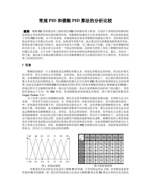
文中分析了振荡的原因并分析如何抑制这种振荡的各种方法,最后,还给出一种方案,通过减少隶属函数的数量以及改善解模糊化的方法缩短控制信号计算时间,有效的改善了控制的实时性。
1 引言模糊控制器的一个主要缺陷就是调整的参数太多。
特别是参数设定的时候,因为没有相关的书参考,所以它的给定非常困难。
众所周知,优化方法的收敛性跟它的初始化设定有很大关联,如果模糊控制器的初始域是固定的,那么它的控制就明显的简化了。
而且我们要控制的参数大多有其实际的物理意义,所以模糊控制器完全可以利用PID算法的控制规律进行近似的调整。
也就是说最简单的模糊PID控制器就是同时采用几种基本模糊控制算法(P+I+D或者PI+D),控制过程中它会根据控制要求,做出适当的选择,保证在处理跟踪以抗阶跃干扰问题上,其控制性能接近于任何一种PID控制。
假设模糊集的初始域是对称的,两个调节器的参数采用Ziegler-Nichols方法。
为了改善上述设计的模糊控制器,我们有必要考模糊控制器的参数问题,有两种方法可以采纳,一种采用手动的方法改变,另一种就是采用一些相关的优化算法。
其中遗传算法就是一种。
控制器采用的参数不同,其收敛的优化值也会不一样。
这些参数包括模糊集的分布,模糊集的个数,映射规则,基本模糊控制器的参数和不同的算法组合等。
- 1、下载文档前请自行甄别文档内容的完整性,平台不提供额外的编辑、内容补充、找答案等附加服务。
- 2、"仅部分预览"的文档,不可在线预览部分如存在完整性等问题,可反馈申请退款(可完整预览的文档不适用该条件!)。
- 3、如文档侵犯您的权益,请联系客服反馈,我们会尽快为您处理(人工客服工作时间:9:00-18:30)。
附录CONTROL, PID CONTROL, ANDADVANCED FUZZY CONTROLFOR SIMULATING A NUCLEARREACTOR OPERATIONXIAOZHONG LI and DA RUAN*elgian Nuclear Research Centre (SCKoCENBoeretang 200, 8-2400 Mol, Belgium(Received 15 March 1999)Based on the background of fuzzy control applications to the first nuclear reactorin Belgium (BRI) at the Belgian Nuclear Research Centre (SCK.CEN), we have made a realfuzzy logic control demo model. The demo model is suitable for us to test and com- pare somenew algorithms of fuzzy control and intelligent systems, which isadvantageous because it is always difficult and time-consuming, due to safety aspects, to do all experiments in a real nuclear environment. In this paper, we first report briefly on the construction of the demo model, and then introduce the results of a fuzzy control,a proportional-integral-derivative (PID) control and an advanced fuzzy control, in whichthe advanced fuzzy control is a fuzzy control with an adaptive function that canSelf-regulate the fuzzy control rules. Afterwards, we present a comparative study of thosethree methods. The results have shown that fuzzy control has more advantages in termsof flexibility, robustness, and easily updated facilities with respect to the PID control ofthe demo model, but that PID control has much higher regulation resolution due to itsintegration term. The adaptive fuzzy control can dynamically adjust the rule base,therefore it is more robust and suitable to those very uncertain occasions.Keywords: Fuzzy control; PID control; fuzzy adaptive control; nuclear reactorI INTRODUCTIONToday the techniques of fuzzy logic control are very mature in mostengineering areas, but not in nuclear engineering, though some research has been done (Bernard, 1988; Hah and Lee, 1994; Lin et al. 1997; Matsuoka, 1990). The main reason is that it is impossible to do experiments in nuclear engineering as easily as in other industrial areas. For example, a reactor is usually not available to any individual. Even for specialists in nuclear engineering, an official licence for doing any on-line test is necessary. That is why we are still conducting projects such as "fuzzy logic control application" in BRl (the first nuclear reactor in Belgium) (Li and Ruan, 1997a; Ruan, 1995; Ruan and Li, 1997; 1998; Ruan and van der Wal, 1998). In the framework of this project, we find that although there are already many fuzzy logic control applications, it is difficult to select the most sui-table for testing and comparison of our algorithms. Moreover, due to the safety regulations of the nuclear reactor, it is not realistic to perform many experiments in BRl. In this situation, we have to conduct part of the pre-processing experiments outside the reactor, e.g., com-parisons of different methods and the preliminary choices of the parameters. One solution is to make a simulation programme in a computer, but this has the disadvantage that inwhich, however, the real time property cannot be well reflected. Therefore another solution has adopted, that is, we designed and made a water-levelcontrol system, referred to as the demo model, which is suitable for our testing and experiments. In particular, this demo model (Fig. 1) is designed to simulate the power control principle of BRl (Li et al., 1996a,b; Li and Ruan, 1997b).In this demo model, our goal was to control the water level in tower TI at a desired level by means of tuning VL (the valve for large control tower T2) and VS (the valve for small control tower T3). The pump keeps on working to supply water to T2 and T3. All taps are for manual tuning at this time. VI and V2 valves are used to control the water levels in T2 and T3 respectively. For example, when the water level in T2 is lower than photoelectric switch sensor 1 then the on-off valve V, will be opened (on), and when the water level in T2 is higher than photoelectric switch sensor 2 then the on-off valve Vl will be closed (off). The same is true of V2. Only when both VI andV2 are closed V3 will be opened, because it can decrease the pressure of the pump and thereby prolong its working life. The pressure sensor is used to detect the height of water level in TI. So for TI, it is a dynamic system with two entrances and one exit for water flow.COMPARATIVE STUDY OF FUZZY CONTROLThe Demo Model StructureFIGURE 1 The working principle of the demo model.BRI is a 42-year old research reactor, in which the control method is the simple on-off method. Many methods called traditional meth- ods, when compared to fuzzy logic, are still very new to theBR1 reactor. One of these, proportional-integral-derivative (PID) control, has to be tested as well as fuzzy logic method. So far, we have tested the normal fuzzy control, traditional PID control, and an advanced fuzzy control on this demo model. To obtain a better demonstration, these three approaches have been programmed and integrated into one con- roller system based on the programmable logic controller (PLC) of the OMRON company. The purpose of tlus paper is to report comparativeexperimental results of these three methods from the demo model. Section 2 simply introduces a normal fuzzy control and its result.Section 3 introduces a PID control and its result.Section 4 introduces an advanced fuzzy control which is able to self-regulate the Fuzzy control rules. Section 5 compares the previous three methods and their results.2 FUZZY CONTROLThe fuzzy control algorithm in this demo model is a normal algorithm based on the Mamdani model. To simulate the BRl reactor, we use two fuzzy controllers (FLCl and FLC2) to control VL and VS separately (note: it is possible to use one fuzzy logic controller with two outputs to control VL and VS and the related result can be referred to (Li and Ruan, 1997b)). Let D be the difference between the actual value (P) of water level and the set value (S) and DD be the derivative of D, in other words, the speed and direction of the change of water level. VL and VS represent the control signal to VL (Iarge valve) and VS (small valve), respectively. When D is too big, we use FLC1 to control VL (main-tuning); When D is small, we use FLC2 to control VS(fine-tuning). We choose D and DD as inputs of the fuzzy logic con- troller, and VL or VS as the output of the fuzzy logic controller. D and DD must be fuzzified before fuzzy inference. Suppose the universes of discourse (or input variables' intervals) of D and DD are -d, dj and [-dd,dd], respectively. We use 7 fuzzy sets to partition hem, i.e., Negative Large (NL), Negative Middle (NM), Negative Small (NS), Zero (ZE), Positive Small (PS), Positive Middle (PM), and Positive Large (PL). As for VL and VS, because the result of fuzzy reasoning is also a fuzzy linguistic value, the universes of discourse of VL and VS also need to be fuzzified. We use those 7 fuzzy linguistic erms too. Symmetrical trianglar-shaped functions are used to define the membership functions for input variables (Li et al., 1995; 1996a,b), and singletons are for output variables (Ornron, 1992). Each fuzzy controller has one rule base which contains 49 fuzzy control rules. The its rule can be represented as the following form: if D is Ai and DD is Bi, then VL (or VS) is Ci where A, Bi, and Ci are fuzzy linguistical values, such as NL, PS, and so on. The above rule is sometimes abbreviated as (Ai, Bi : Ci). Figure 2 shows a control effect of a synthetic control process. It first goes up from 0 to 20cm then keeps on at 20 an, next drops down from 20 to 10 cm and finally keeps on at 10 cm.In view of this figure, we know that the fuzzy control has quick responses (quickly approaching the set value) and small overshoot (almost invisible), but with a small steady error (not so smooth in a steady state).COMPARATWE STUDY OF FUZZY CONTROLFIGURE 2 The control effect of fuzzy control to the demo model.3 PID CONTROLIn the PID control, it is difficult to control VL and VS separately like the previous fuzzy control with a good control result, because the integration term of the PID control needs some time, and this will result in an oscillation when switching control signal between VL and VS. From this point ofview the PID control is worse than the fuzzy control. Therefore, in our tests, VL and VS have to be controlled by the same signal. We use the following formula:dtde d i pe T dt T e K U(t)++=⎰By substitution, dtde d ie pe K dt K K U(t)++=⎰where U(I): control value to VL and VS at time r; e: the set value-the real value at time I; Kp: the proportional parameter and Kp = (1IPB) x loo%, where PB is the proportional band; Ki: the integrationFlGURE 3 The trajectory of the water level by the PID control.parameter and Ki = l/Ti where Ti is the integration time; Kd: the differential parameter and Kd = Td where Td is the differential time. In practice, a discrete form of the above formula is used)]1()([)](....)2()1([K e(t)K U(t)i P --++++=t e t e T K t e e e T sd swhere T, is the sample period. Figure 3 shows a result of the PID control,where PB= l5%, Ti=30s, Td= 10s. In view of this figure, the PID control is very stable (very smooth in steady states), and has quick responses too, but with visible overshoots.4 ADVANCED FUZZY CONTROLThe kernel part of the fuzzy logic control is the fuzzy rule base with linguistic terms, though the membership functions and scale factors also have an important effect on the fuzzy logic controller. There are some papers which discuss how to adjust membership functions and/or scale factors (Batur and Kasparian, 1991; Chou and Lu, 1994; Tonshoff and Walter, 1994; Zheng, 1992). This section focuses on rules. Normally the methods of deriving rules can be broadly divided into two types, sourceable and non-sourceable. The sourceable method means the rules are obtained from some information source, such as human experience or historical input-output data. Experience has been widely used by the fuzzy engineers, especially by the early fuzzy engineers. The problem of using human experience is that it is time-consuming, and to some degree subjective. In order to overcome these problems, particularly avoiding the subjectivity, historical input -output data-if available can be used. To obtain rules from such data, many methods are used, one of the popular approaches is neural net- works (NN) (Berenji and Khedkar, 1992; Halgamuge and Glesner, 1994; Jang, 1992; Kosko, 1992; Li et al., 1995; Lin ez al., 1995; Takagi and Hayashi, 1991; Wang and Mendel, 1992). One problem of the sourceable method is that it depends strictly on the source which will be transformed into rules. In the case that the source is noisy, then the rules might be biased. Another problem of the sourceable method is that it is usually non-adaptive, i.e., all the rules are fixed, therefore it cannot perform well under a dynamic environment. The non-source- able methods are source-free and they produce and choose rules according to a performance measurement of the controller, such asgenetic algorithms (GA) (Karr, 1991; Lim et al., 1996; Qi and Chin, 1997) (mostly also generating membership functions and scale factors) and self-organizing controllers (SOC) (He er al., 1993; Li et al., 1996a,b; Lin et al., 1997, Procyk and Mamdani, 1979; Shao, 1988; Tanscheitand Scharf, 1988; Wu et al., 1992). With GA it is possible to find integratedly optimal parameters but GA is very computation rich, and furthermore, it is almost impossible to apply GA in a real complex system without a simulation model. Perhaps the SOC is the only method which has the following advantages: objective, adaptive, less computation required, more error-tolerant, and simple.FIGURE 4 An adaptive function is incorporated into a fuzzy control system.The general principle of the SOC is that the controller monitors its own performance and adjusts its control rules to improve performance for time-varying and unknownplants. The problem of the SOC show to perform the performance measurement. The basic way is to design a performance measurement table which looks like a fuzzy control rule table and to use it to assess the performance of the controller rules) (Procyk and Mamdani, 1979), but to design such a performance measurement table is also very difficult (Chung and Oh, 1993) and it is system-dependent. Based on the SOC, this section will introduce an adaptive method which uses a set of new norms to replace the ormer performance measurement. The new norms are very simple and system-independent, therefore they can be easily applied to most fuzzy controllers. In this section, the advanced fuzzy control means the above SOC, in other words, a fuzzy control with an adaptive function, where the adaptive function contains two steps: performance judgement and changing fuzzy control rules. Figure 4 illustrates how an adaptive function is incorporated into the fuzzy control system. At the beginning of each cycle, the controller's last behaviour is judged and then the rule base is changed accordingly. In this cycle, the controller will use the new rule base and output the result to the controlled object. The behaviour of the new rule base will be judged and changed again in the next cycle.4.1 The Principle of the Adaptive FunctionLet D and DD represent error (the difference between the actual value and the desired value) and change in error, respectively. Let D(t) and DD(t) represent error and change in error at time t, respectively. They are two input variables. Let U be an output variable, and assume thetotal number of the rules is n, then every rule has the following form: if D is A, DD is Bi, then U is C;, i= 1,2 ,..., n, where A, Bi, and Ci are fuzzy linguistic values and i is an index pointing out each rule's position in the rule table (or the rule data file). User[i] to represent the fuzzy control magnitude (conclusion fuzzy set) of the ith rule, and let simplyi r7,6,5,4,3,2,1][where 1=NL,2=NM,3=NS,4=ZE,5=PS,6=PMY7=PL.In general, a control locus may be expressed with Fig. 5, and it can be regarded as having up to four feature sections and four feature points. For each feature part, we offer a norm to guide the regulation of the fuzzy control rules. For example, the current water level P(t) is in the feature part (I), then after the fuzzy controlling using the current control rules, we measure the water level P(t + l) at the next time which has three possibilities:P(l) < P(t + 1) <S;P(t + 1) < S and P(t + 1) <P(t);P(t+l)>S.FIGURE 5 Any trajectory has up to four feature sections and four feature points.The related norm to guide how to change rules is the following:(i) if D(I + 1) 5 0 and DD(t + I) > 0, that is, P(t) < P(t + 1) 5 S, then r[i] = r[i](ii) if D(i f 1) < 0 and DD(t + 1) < 0, that is, P(t +1) < S and P(t + 1) < P(t), then r[i] = r[i] +a,(iii) if D(t + 1) > 0, that is, P(t + 1) > S, then r[i] = r[i] - a,where a is a step size and a = 1,2,3,4,5,6. In case (i), the fuzzy con-troller makes the water level P(t f 1) closer to the set value S, therefore the behaviour of the fuzzy controller is good, no rules should be changed; In case (ii), the fuzzy controller makes the water level P(t + 1) further from the set value S, therefore the behaviour of the fuzzy con- troller is not good, the strength is too weak and the action of the corresponding rules 'should be stronger; In case (iii), the fuzzy controller makes the water level P(t $1) overpass the set value S, therefore the behaviour of the fuzzy controller is not good, the strength is too strong and the action of the corresponding rules should be weakened. Not all rules but some of those that are activated in last cycle should be regulated. We use the following formula to describe which shouldbe adjusted:))()(A ()()(A j j i i DD B D DD B D ij C C ∧∨=∧= which means the ith rule is changed only if it is the largest activated among those activated rules which have the same conclusion part. For example, (NL, NM : PL) and (NM, NM : PL) are two activated rules and have the same conclusion part, i.e., PL. Comparing NL(D) A NM(DD)with NM(D) A NM(DD), the larger one corresponds to the rule which should be adjusted.4.2 An Experimental ResultTo guarantee no overshoot, the best way is to initialize all rules as the same conclusion part: NL, as shown in Table I. In this table, for example, NL at the row 2 and column 3 means: if D is NM and DD is NL then VL or VS is NL. All rules have the same conclusion part though condition parts are different. Figure 6 illustratesTABLE I The initial rule table for both FLCl and FLC2FIGURE 6 Comparison between adaptive fuzzy control and fuzzy control.the comparison result between fuzzy adaptive control and. fuzzy con-trol with the above rule base. In this example, the set value is 20cm.Both start from Ocm. During the first stage, i.e., increasing from zero,some analytic rules manipulate the valves and not fuzzy control. Onlyafter the water level reaches 18cm does the fuzzy controllers start tooperate VL and VS. Apparently, the adaptive fuzzy control has a muchbetter result by self-regulating gradually fuzzy control rules. The nor-mal fuzzy control without adaptive function cannot self-regulate rules,therefore it cannot draw up the water level.About 10 min later, we observe the rule tables on the screen and findboth rule tables have changed a lot. Table I1 gives the result of FLCl and Table 111 gives the resultof FLC2, where the regulated rules aremarked by bold fonts.4.3 Some Remarks for the Adaptive FunctionThe initial idea about the previously described norms of the adaptive function, which was published in (Li et al., 1996a,b), and where a simulated inverted pendulum system and a real industrial heating system were used to make testings, gave satisfactory results . a The parameter a is influential on the overshoot and response time (rise time). When cr is too big, there will be a large overshoot possibly; when a is too smaI1, possibly there will be a long response time (Li el al., 1996a,b). The adaptive function considers only the last value, that is, it uses P(r - 1) not P(t - T) (T is the delay) to decide P(t), but our experimental results show the effect is good, although the valves of the demo model have a maximum delay of 90 s. The adaptive function selects only some of the rules according to formula (1) for adjustment, not all activated rules like (Lin et al., 1997). This makes the transition of the rules more smooth, i.e., without or with less resonance. Selecting initial rules appropriately will benefit the control effect. For example,if the overshoot is strictly limited, we may initialize all rules with the conclusion part of NL, as was done in the previous experiment. Once some experience has been obtained, it can be transformed into the initial rules of the adaptive function, the advantage being that the rise time will be shorter (Li and Ruan, 1998). The rule, "if D is ZE and DD is ZE then U is ZE," should be fixed, and this will help the system to become stable. The adaptive function is very helpful in keeping the system stable in a steady state. It cannot guarantee no overshoot if the initial rules are randomly selected. The adaptive function cannot adjust membership functions and scale factors.5 COMPARATIVE STUDYEach method has both advantages and disadvantages, the details of which are described in Table IV, where * is used to represent the degree of a property, and the more *, the higher the degree. For example, the realization of an adaptive fuzzy logic controller (FLC) is more difficult than a normal fuzzy controller, but a normal fuzzy controller is more difficult to realize than a PID controller. The PID control has the smallest static error and steady error. The dynamic regulation of TABLE IV Comparative study of FLC, PID and adaptive FLC the control rules in an adaptive controller can help in reducing the static error and steady error (Li et al., 1996a,b). As for robustness, it has been accepted that FLC is more robust than PID. Herein we also give one example, as shown as in Fig. 7. This experiment was carried out after tuning the Tap 1 (see Fig. 1) to make the outflow much smaller. We found that the reaction of FLC was better than that of PID, hough the FLC had a small static error. If we count the total number of * for each method, we will find that PID and FLC have the same score, 17. Adaptive FLC has a higher score of 20. This interesting result can be explained by the following facts. PID and FLC have their own strong points, and they compensate each other. Adaptive FLC adds an adaptive function to a normal FLC, therefore its score should be higher than that of FLC. A natural result is that combining FLC and PID should be better than each method alone. The comparative method above is perhaps a little subjective, but it does reflect some objective properties and relationships among those three methods. In the real world, one may use other ways to evaluate these methods. For example, if robustness is stressed, then it should be highly weighted when the total scores are calculated. For further descriptions of comparative studies between FLC and PID, readers may refer to Boverie et al. (1991), Chao and Teng (1997), Misir et al. (1996), Mizumoto (1995), Moon (1995), and Wu and Mizumoto (1996).FIGURE 7 FLC is more robust than PID.6 CONCLUSIONThis paper gives comparisons between fuzzy control, PID control, and advanced fuzzy control based on the experimental results of a demo model which simulates the control principle of the BR1 reactor. Fuzzy control is more robust than PID control, but with a well-characterized system, such as a reactor, it should be better to use a hybrid method which inherits the advantages of both methods. Furthermore, the adaptive fuzzy control is able to aid the designer in finding the fuzzy control rules, especially for systems possessing much of dynamical uncertainty. ReferencesBatur, C. and Kasparian, V. (1991), 'Adaptive expert control," International Journal of Control, 54(4), 867-88 1.Berenji, H.R. and Khedkar, P. (1992). 'Learning and tuning firq logic controllers through reinforcements," IEEE Trans. Neural Networks, 3,724-740.Bernard, J.A. (1988). 'Use of a rule-based system for process control," IEEE Control System Magazine, 8(5), 3- 13.Boverie, S., Demaya, B. and Titli, A. (1991). 'Fuzzy logic control compared with otherautomatic control approaches," Proceedings of the 30th IEEE-CDC Conjerence onDecision and Control, Brighton, UK, pp. 1212-1216.Chao, C.T. and Teng, C.C. (1997), 'A PD-like self-tuning fuzzy controller without steady-state error," Fuzzy Sets and System, 87, 141 -154.Chou, C.H. and Lu, H.C. (1994), 'A heuristic self-tuning fuzzy controller," Fuzzy Setsand Systems, 61,249-264.Chung, B.M. and Oh. J.H. (1993). 'Control of dynamic systems using fuzzy learning algorithm," Fuzzy Sets and Systems, 59, 1 - 14.Hah, Y.J. and Lee, B.W. (1994), 'Fwy power control algorithm for a pressurized water reactor," Nuclear Technology, 106,242-252.Halgamuge, K. and Glesner, M. (1994), 'Neural networks in designing fuzzy systems forreal world applications," Fuzzy Sets and Systems, 65, 1- 12.He, S.Z., Tan, S.H., Hang, C.C. and Wang, P.Z. (1993). 'Control of dynamical pro-cesses using an on-line rule-adaptive fuzzy control system," Fuzzy Sets und Systems,54, 1 1-22.Jang, J.S.R. (1992), "Self-learning fuzzy controllers based on temporal back propaga- tion," IEEE Trans. Neural Networks, 3(S), 714-723.Karr, C.L. (1991). 'Design of an adaptive fuzzy logic controller using a genetic algo- rithm." Proc. 4th ICGA, pp. 450-457.Kosko, B. (1992), Fuzzy Systems and Neural Networks, Prentice-Hall, Englewood Cliffs,NJ.Li, X. and Ruan, D. (1997a), The Current Development of FLC Project at BRI andNew Algorithms Design, Internal Report, SCKmCEN, Mol, Belgium.Li. X. and Ruan, D. (1997b). 'Constructing a fuzzy logic control demo model at SCKaCEN," Proceedings of the 5th European Congress on Intelligent Techniques andSofr Computing (EUFIT '97). Aachen, Germany, pp. 1408-1412.Li, X. and Ruan, D. (1998), A Rule-Based Multi-Controller System Method with an Adaptive Function for the BRI Reactor, Internal Report, SCKmCEN, Mol, Belgium.Li, X., Shao, M. and Ruan, D. (1996a). Fuzzy Logic Control Demo Model, Internal Report. SCKoCEN, Mol, Belgium.Li, X., Bai. S. and Zhang, Z. (1996b), 'An introduction to a fuzzy adaptive control algo- rithm," Chinese Journal of Advanced Software Research, 3(1), 1 - 11.Li. X., Bai, S. and Liu, Z. (1995), 'An algorithm for self-learning and selfcompleting fuzzy control rules,' Informatica, 19, 301 -312.Lim, M.H., Rahardja, S. and Gwee, B.H. (1996), 'A GA paradigm for learning fuzzy rules," Fuzzy Sets and Systems. 82, 177- 186.Lin. C., Jeng, F. and Lee, C. (1997), "Hierarchical fuzzy logic water level control in advanced oiling water reactors," Nuclear Technology, 118(3), 254-263.Lin, C.T., Lin, C.J. and George Lee, C.S. (1995). 'Funy adaptive learning control net-work with on-line neural learning," Fuzzy Sets and Systems, 71.25-45.Matsuoka, H. (1990), 'A simple fuzzy simulation model for nuclear reactor system dynamics," Nuclear Technology, 94, 228-24 1.Misir, D., Malki, H.A. and ,Chen, G. (1996), "Design and analysis of a fuzzy proportional-integral-derivative controller," Fuzzy Sets andSysrems, 79,297-314.Mizurnoto, M. (1995). 'Realization of PID controls by fuzzy control method," Fuzzy Sers and Systems, 70, 171 - 182.Moon, B.S. (1995), 'Equivalence between fuzzy logic controllers and PI controllers forsingle input systems," Fuzzy Sets and Systems, 69, 105- 114.Omron (1992), C200H-FZ001 Fuzzy Logic Unit, Operation Manual, Ornron company.Procyk, T.J. and Mamdani, E.H. (1979), 'A linguistic self-organizing process con- troller,* Automat., 15(1), 15-30.Qi, X.M. and Chin, T.C. (1997). 'Genetic algorithms based fuzzy controller for high order svstems." Fuz:v Sets and Svstems. 91.279-284. . .Ruan. D. (i995). '~uzz;logic in the nuclear research world." Fuzzy Sets and System.74(1), 5-13.Ruan, D. and Li, X. (1997). "The test of fuzzy logic control with a closed loop at BRI reactor," Proceedings of the 7th World Congress IFSA'97, Prague, Czech Republic,Vol. 3, pp. 126-131.Ruan, D. and Li. X. (1998). 'Fuzzy-logic control applications to the Belpan reactor I (BRI)," Computers and Artificial Intelligence. 17(2-3), 127-150.Ruan, D. and van der Wal, A.J. (1998). 'Controlling the power output of a nuclear reac-tor with fuzzy logic," Information Scienkes, 110. 151 - 177.模糊的比较研究控制,PID控制,先进的模糊控制用于模拟核反应堆运行李晓东和阮达比利时核研究中心(SCK CENBoeretang2008-2400摩尔,比利时(1999年3月15日)基于模糊控制应用在比利时的第一座核反应堆(BRI)在比利时核研究中心(SCK.CEN)的背景上,我们已经取得了真正的模糊逻辑控制的演示模型。