毫伏表使用说明GVT-417B
固纬GVT-427B毫伏表说明书

Contents Page Safety Terms and Symbols (1)Introduction (4)Preliminary Notes (5)Panel Description (6)Operation Method (10)Specifications (13)Maintenance (16)Cleaning (16)Troubleshooting (16)Interchangeable Parts (17)SAFETY TERMS AND SYMBOLSThese terms may appear in this manual or on the product:WARNING. Warning statements identify condition orpractices that could result in injury or loss of life.CAUTION. Caution statements identify conditions orpractices that could result in damage to this product or other property.The following symbols may appear in this manual or on the product:DANGER High VoltageATTENTION refer to ManualProtective Conductor Terminal(Ground) Earth TerminalFOR UNITED KINGDOM ONLYNOTE: This lead/appliance must only be wired bycompetent personsWARNING: THIS APPLIANCE MUST BE EARTHED IMPORTANT: The wires in this lead are coloured inaccordance with the following code:Blue: NeutralBrown: Live (Phase)As the colours of the wires in main leads may not correspondwith the colours marking identified in your plug/appliance,proceed as follows:The wire which is coloured Green & Yellow must be connected toThe wire which is coloured Blue must be connected to the terminal which is marked with the letter N or coloured Blue or Black.The wire which is coloured Brown must be connected to the terminal marked with the letter L or P or coloured Brown or Red. If in doubt, consult the instructions provided with the equipment or contact the supplier.This cable/appliance should be protected by a suitably rated and approved HBC mains fuse : refer to the rating information onthe equipment and/or user instructions for details. As a guide,cableof 0.75mm²should be protected by a 3A or 5A fuse. Larger conductors would normally require 13A types, depending on the connection method used.Any moulded mains connector that requires removal /replace- ment must be destroyed by removal of any fuse & fuse carrier and disposed of immediately, as a plug with bared wires is hazardous if a engaged in live socket. Any re-wiring must be carried out in accordance with the information detailed on this label.IntroductionGVT-427B is versatile AC voltmeter which is able to measure AC voltage from ranges of 10 Hz to 1 MHz with full scale ranges from 300 μV to 100 V. The dB scale measures 1V as 0dB and ranges from -90 dB to +41 dB. The 600 Ω (1mW) dBm scale ranges from -90 dBm to +43 dBm.The scales on the meter are graduated up to 1.1 (for +1dB) and these extended scales are especially useful when measuring the characteristics of audio amplifiers. In addition, both instruments can give AC voltage output of approximately 0.1V in full scale from the output terminals, and the measurements can therefore be monitored. GVT-427B is a two channels voltmeter with isolated output for each channel which enables it to be used as a two channels preamplifier.Preliminary Notes1. Chassis grounding terminal:Make sure the chassis ground terminal is connected to the earth before inserting the power plug into the main supply.2.Maximum input voltage:The voltmeter may be damaged if any input voltage exceeding the specified voltage is applied to it. The specified voltage is determined by adding the peak value of the input signal and the superimposed DC voltage: 300 V for the 300 μV ranges, and 500 V for the 3 V to 100 V ranges.3.Connection leads:When the measured signal level is low (i.e. 300 μV) or the measured signal source impedance is high, the input line is susceptible to external noise. To resist the noise, shielded wires or a coaxial cable should be used depending on the noise frequency.4.Full scales:GVT millivoltmeter adopts a special extended scale which has a reading range larger than the conventional full scale.Note that the term “full scale” considers …1.0‟ on the 0 - 1.12 scales as the rated value. The red ▼mark is setting at …1.0‟ on the outermost scale.Panel Description(1) MeterProvide easy readings for both voltage and dB scales. For GVT-427B, the black pointer is CH 1 and the red one is CH 2. (2) ZERO adjustment(6), (7) ZERO adjustmentMechanical ZERO adjustment for the pointer. For GVT-427B, the black-mark screw (6)is to adjust CH 1 pointer whereas the red-mark screw (7) is to adjust CH 2.(3) Range selector switch(8),(9) CH 1 and CH 2 Range selector switch10 dB step attenuator to select a desired voltage range for aneasy readout. When the mode switch (14)of GVT-427B is DISENGAGED, CH 1 and CH 2 range can be selected independently. However, when the mode switch is DISENGAGED, the CH 2 range will change according to the selected CH 1 irrespective of the CH 2 selector switch (9) position.(4) Input connector(10),(11) CH 1 and CH 2 input connector respectivelyThe terminal where the measured signal is applied.The maximum voltage of DC isolation is ±30 V (peak value)(5) Output connector(12),(13) CH 1 and CH 2 Output connectorrespectivelyProvide output signals when the meter is used as a preamplifier.When the range selector switch is setting at 100 mV, the output voltage will be approximately equal to the input voltage.However, when the range selector switch is setting to the next higher or lower voltage range, the amplification factor is decreased or increased by 10 dB respectively.(14) Mode switchIf this button is setting as DISENGAGED, the CH 1 and CH 2 range selector switches could select their related own ranges. If the mode switch has been pressed, the CH 1 range selector switch could select both CH 1 and CH 2 voltage ranges simultaneously, and the CH 2 range selector switch would be ineffective.(15) Grounding selector switchIf this switch is setting to the upper position, the CH 1 and CH 2 Input Command Lines are isolated from each other, and they are floated relative to chassis ground through a res istance of 100 k . If the switch is setting the down position, both lines could be connected directly to the chassis.The maximum voltage of DC isolation is ±30 V (peak value)(16) Power Indicator(17) Power Switch(18) Appliance AC InletOperation MethodA.Voltage measurement1. Turn off the power.2. Check the ZERO setting of the pointers. If there is offset,you could use a screwdriver to adjust the zero adjustmentscrew at the center of the meter front cover.3. Plug the AC plug into the AC line.4. Set the RANGE to 100 V and turn on the power.5. Connect leads to the INPUT terminal and the load is undertesting.6. Alter the RANGE selector switch until the pointer is at aposition which located at ≧1/3 of the scale, therefore, thereading can be taken easily.e of decibel rangesThere are two dB scales provided on the dial which have been calibrated as0 dB = 1 V0 dBm = 0.775 V (1 mW into 600 )1. dB:“Bel” is a logarithmic unit which expresses the ratio of two powers. One “decibel” (abbreviated dB) is one-tenth of a Bel.The dB is defined as follows:dB = 10 log P2 / P1If the impedance is at the place where P1 and P2 are equal to each other, the ratio of power could be expressed as follows:dB = 20 log E2 / E1 = 20 log I2 / I1Decibel is originally the ratio of power as explained above. However, the logarithm of the ratio of other values (ratio of voltage or current) can also been called “decibel”.For example, If the input voltage of an amplifier is 10 mV and its output voltage is 10 V, the degree of amplification could be 10 V / 10 mV = 1000 times. This is also expressed in dB as follows: Degree of amplification = 20 log 10 V / 10 mV = 60 dB2. dBm“dBm” is the abbreviation of dB (mW). This decib el value expressed the power ratio with respect to 1 mW. Normally, “dBm” implies the condition where the power exists in an impedance of 600Therefore, “0 dBm” can be signified as the following:0 dBm = 1 mW or 0.775 V or 1.291 mA3. The power or voltage levels are determined by adding up the scale readings and the selected RANGE settings. Example:Scale RANGE Level(-1 dB) + (+20 dB) = +19 dB(+2 dBm) + (+10 dBm) = +12 dBm4. The dB and dBm scales of the indicating meter are as stated the following:SpecificationsThis section contains a table of GVT-427B characteristics. Table 1: SpecificationsTable 1: Specifications (Cont.)Table 1: Specifications (Cont.)*: Dual scales in different colors.**: Between the input common and chassis.MaintenanceThis section includes the basic maintenance information for GVT-427B. CleaningTo clear GVT-427B, use soft cloth dampened in a solution of mild detergent and water. Do not spray cleaner directly onto the instrument, since it may leak into the cabinet and cause damage.Do not use chemicals containing benzine, benzene, xylene, acetone, toluene, or similar solvents.Do not use abrasive cleaners on any portion of this equipment. TroubleshootingTroubleshooting the GVT-427B is limited to checking the input power fuse. If you have other operational difficulties with your GVT-427B, contact your Good-Will representative for assistance.WARNING. To avoid electrical shock, the power cord protective grounding conductor must be connected toground.WARNING. To continued fire protection. Replace fuse with the specified type and rating, and disconnectthepower cord before replacing fuse.Interchangeable PartsInterchangeable parts can be ordered from your authorized Goodwill dealer directly.AccessoriesThe items are shipped with the GVT-427B as following:Table 2: Accessories。
毫伏表操作规程通用范本

内部编号:AN-QP-HT195版本/ 修改状态:01 / 00 The Procedures Or Steps Formulated T o Ensure The Safe And Effective Operation Of Daily Production, WhichMust Be Followed By Relevant Personnel When Operating Equipment Or Handling Business, Are Usually Systematic Documents, Which Are The Operation Specifications Of Operators.编辑:__________________审核:__________________单位:__________________毫伏表操作规程通用范本毫伏表操作规程通用范本使用指引:本操作规程文件可用于保证本部门的日常生产、工作能够安全、稳定、有效运转而制定的,相关人员在操作设备或办理业务时必须遵循的程序或步骤,通常为系统性的文件,是操作人员的操作规范。
资料下载后可以进行自定义修改,可按照所需进行删减和使用。
使用注意事项1、避免仪器过冷或过热,仪器的工作温度为0—40℃。
2、仪器不可遭到强烈的撞击。
3、不可将物体放置在仪器上,注意不要堵塞仪器通风孔。
4、不可将磁铁靠近表头。
5、表面长期倒置存放和运输。
6、检查表针位置,若不在零点先调零。
7、仪器工作电压为AC220V,不可高于规定的最大输入电压。
使用方法1、开机前,应将量程旋钮调到最大量程处,然后打开电源。
2、将输入信号由输入端口(INPUT)送入交流毫伏表。
3、调节量程旋钮,使表头指针指示位置在大于或等于满刻度的1/3处。
4、量程的使用方法:表头有两种刻度。
其中1V作为0dB的dB刻度值,0.755V作为0dBm(1mW)的dBm刻度值。
拟投入的主要施工机械设备表模板

线缆检测
9
手动液压压接钳
HK-12030 120kn
0
管线施工
10
数字钳形表
VA-310 直流100V,交流750V,电流200ma-20a-1000a,电阻200欧-2000欧
0.009
设备安装
11
数字多用万用表
VA18B-6000 测量交直流电压,电流,电阻,温度,温度,频率等
0.005
12
管线施工
39
直流手工电焊机
ZX7-200 AC220V,0.93KW
0.93
管线施工
40
台钻
西湖台钻\Z4025 16mm,750W
0.7530(A-PSE(L))/2G/160G/14"
0.05
工程管理
42
工程用车
江铃
安装调试
设备安装
12
管道锯空机
HC-450 0.43/4"
0.75
管线施工
13
长颈弯头钻机
WB220E 00-15000rpm,200-240v,100w
0.1
管线施工
14
超级电工组套工具
PRO-115 曲线锯机+砂光机+钻磨机+充电电池
0.36
设备安装
15
充电式切割机
EK425C 44kn
0.5
管线施工
16
充电钻/起子
ABS12 钻孔(钢)13mm,(木)30mm
0.285
设备安装
17
电动弯管机
ROBEND 3000 14-35mm
1.5
管线施工
18
电烙铁
EL12 预热10s
毫伏表GVT-427B使用说明
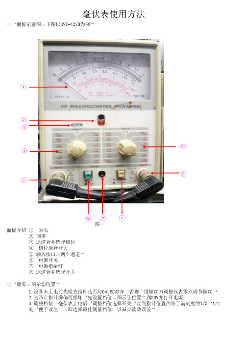
毫伏表使用方法一、面板示意图(下图以GVT-427B为例)面板介绍:① 表头 ② 调零 ③ 通道合并选择档位 ④ 档位选择开关 ⑤ 输入接口(两个通道) ⑥ 电源开关 ⑦ 电源指示灯 ⑧ 通道合并选择开关图一二、调零(图示②位置)1.设备未上电前先检查指针是否与0刻度对齐;否则,用螺丝刀调整仪表零点调节螺丝; 2.为防止指针满偏而损坏,先设置档位(图示④位置)到30V并打开电源; 3.调整档位:毫伏表上电后,调整档位选择开关,直到指针位置约等于满刻度的1/3、1/2 处,便于读值;(即选择最佳测量档位,以减少读数误差)三、读值方法1 选择要读取的刻度表头刻度盘上共刻有四条刻度;第一条刻度和第二条刻度为测量交流电压有效值的专用刻度,第三条和第四条为测量分贝 值的刻度。
当量程开关分别选1mV、10mV、100mV、1V、10V、100V档时,就从第一条刻度读数;(逢1就从第一条刻度读数,逢3从第二刻度读数)当量程开关分别选3mV、30mV、300mV、3V、30V、300V时,应从第二条刻度读数(逢1就从第一条刻度读数,逢3从第二刻度读数)第一条刻度最小单位数值为2X(最小数值的单位取值与所选档位有关,如1V档,则最小单位为0.02V)第二条刻度最小单位数值为1X(最小数值的单位取值与所选档位有关,如3V档,则最小单位为0.1V)2 计算实测电压值如图所示(后两组数据为另外增加),按如下公式计算电压。
刻度:0.5 × 档位:100mV = 50mV刻度:2.0 × 档位:30mV = 20mV刻度:0.54 × 档位:1V= 0.54V刻度:2.3 × 档位:3V= 2.3V3 分贝读值法第三条和第四条为测量分贝值的刻度,分贝值为一个相对参考值,可取第三或第四刻度中 任一条作参考,每个档位之间的差值为10DB,如表上的刻度不足以读数,则通过档位调节 进行量程的准确读数例:1.以第四条刻度的0DB作为参考值,当被测品音量减小使指针处于第四刻度的-5位 置,则调节前后,两个音量等级的相对分贝值为-5DB2.被测品的两个信号输入幅度不同,导致两条指针之间存在一定的差值,以第三刻度 为例,一条指针在-2位置,另一条指针在-7.5位置,则两条指针所表示的分贝差值为(2)-(-7.5)=5.5DB四、通道的联调及单独调节(图一)⑧所示为CH1和CH2的范围选择开关,当这个开关处于弹起的状态时,CH1和CH2的测量范围是 相互独立的,当开关处于按下去的状态时候,CH1和CH2的范围将一起根据CH1范围旋钮④的调 节而改变五、指针及信号输入口的定义1信号输入通道--一般定义正对毫伏表左侧的输入通道为测试品的左声道信号(图一左⑤, 黑字体INPUT),右侧的输入通道为测试品的右声道信号(图一右⑤,红字体INPUT)2指针--若测试品信号输入按上述1,则黑色指针代表测试品左声道输出幅度,红色指针代 表测试品右声道输出幅度3若测试品左右声道输出的信号相同(即无单边信号输入),则两指针的输出差异允许误差 在1DB范围内。
毫伏表操作规程标准范本

操作规程编号:LX-FS-A73018 毫伏表操作规程标准范本In The Daily Work Environment, The Operation Standards Are Restricted, And Relevant Personnel Are Required To Abide By The Corresponding Procedures And Codes Of Conduct, So That The Overall BehaviorCan Reach The Specified Standards编写:_________________________审批:_________________________时间:________年_____月_____日A4打印/ 新修订/ 完整/ 内容可编辑毫伏表操作规程标准范本使用说明:本操作规程资料适用于日常工作环境中对既定操作标准、规范进行约束,并要求相关人员共同遵守对应的办事规程与行动准则,使整体行为或活动达到或超越规定的标准。
资料内容可按真实状况进行条款调整,套用时请仔细阅读。
使用注意事项1、避免仪器过冷或过热,仪器的工作温度为0—40℃。
2、仪器不可遭到强烈的撞击。
3、不可将物体放置在仪器上,注意不要堵塞仪器通风孔。
4、不可将磁铁靠近表头。
5、表面长期倒置存放和运输。
6、检查表针位置,若不在零点先调零。
7、仪器工作电压为AC220V,不可高于规定的最大输入电压。
使用方法1、开机前,应将量程旋钮调到最大量程处,然后打开电源。
2、将输入信号由输入端口(INPUT)送入交流毫伏表。
3、调节量程旋钮,使表头指针指示位置在大于或等于满刻度的1/3处。
4、量程的使用方法:表头有两种刻度。
其中1V作为0dB的dB刻度值,0.755V作为0dBm (1mW)的dBm刻度值。
5、功率或电压的电平由表面读出的刻度值与量程开关所在的位置相加而定。
保养和维护1、本仪器由高精度的元器件及精密部件构成,因此在运输和储存时,须小心轻放。
毫伏表主要技术参数与操作使用资料

主要技术参数用电量:小于40mA,电池寿命约40至50小时量程Q范围:第1量程10至240,第2量程Q范围:50至1200DDS幅度温漂:200ppm/℃信号源温漂,小于0.03%/℃(估计)主调电容最大值Cmax = 512.4pF主调电容最小值Cmin = 31.9pF毫伏表线性度误差:40%量程至满量程误差小于0.5%,10%至40%小于1%,5%量程误差4%,小于5%量程误差很大。
毫伏表零点误差:1至2个字毫伏表温漂:与零点误差有关毫伏表调零后有效字数:898±20字,与检波器的偏置电压有关毫伏表矫正输出字数:约1250字毫伏表频率响应:大于10MHz激励磁环电压变换比误差:100kHz至10MHz,误差小于0.5%激励磁环残余电阻:小于3毫欧激励磁环残余电感:小于20nH主可变电容残余电感:45nH主可变残余电阻:未知(中波段约数毫欧,铜损可由趋电阻估计,介质损耗不好估计)接线柱及引线的残余电阻:未知(比较大)场效应管输入阻抗:10MHz,约150千欧(利用数据表估算);1MHz,1兆欧;阻抗估算不含电路板的损耗,考虑电路板的损耗,实际阻抗按70%计算即可毫伏表输入总阻抗:10MHz,10兆欧;1MHz,70兆欧毫伏表两个两程测量的一致性:在50kHz至10MHz,全部一致,误差通常在2%以内。
低量程换为高量程,会落在20%量程以下,所以误差变大。
自动关机:如果8分钟内,没有键盘操作,系统将自动关机。
本电路没有设计电池电压检测电路,当电池的电压低于3.0V时,Q表无法正常工作,测量值也不精确,建议用户定期测量电池电压。
测线圈Q值的精度:第1量程中波段精度一般优于3%,第2量程与接线柱、可变电容的损耗有关,使用优质电容,中波段误差小于5%,差的电容测不了高Q。
第1量程,6MHz以上,误差小于3%,8MHz以上,误差5%。
测线圈Q值的精度是读者比较关心的问题,其实这个指标说明不了多少问题,因为线圈的状态,线圈引线、接线柱等的影响,测电感Q值精度不会很高的。
交流毫伏表的使用
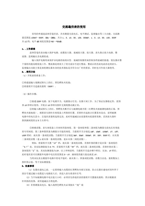
交流毫伏表的使用常用的单通道晶体管毫伏表,具有测量交流电压、电平测试、监视输出等三大功能。
交流测量范围是100nV~300V、5Hz~2MHz,共分1、3、10、30、100、300mV,1、3、10、30、100、300V共12档;电平dB刻度范围是-60~+50dB。
1、.工作原理晶体管毫伏表由输入保护电路、前置放大器、衰减放大器、放大器、表头指示放大电路、整流器、监视输出及电源组成。
输入保护电路用来保护该电路的场效应管。
衰减控制器用来控制各档衰减的接通,使仪器在整个量程均能高精度地工作。
整流器是将放大了的交流信号进行整流,整流后的直流电流再送到表头。
监视输出功能主要是来检测仪器本身的技术指标是否符合出厂时的要求,同时也可作放大器使用。
2、.使用方法(1)开机前的准备工作:①将通道输入端测试探头上的红、黑色鳄鱼夹短接;②将量程开关选最高量程(300V)。
(2)操作步骤:①接通220V电源,按下电源开关,电源指示灯亮,仪器立刻工作。
为了保证仪器稳定性,需预热10秒钟后使用,开机后10秒钟内指针无规则摆动属正常;②将输入测试探头上的红、黑鳄鱼夹断开后与被测电路并联(红鳄鱼夹接被测电路的正端,黑鳄鱼夹接地端),观察表头指针在刻度盘上所指的位置,若指针在起始点位置基本没动,说明被测电路中的电压甚小,且毫伏表量程选得过高,此时用递减法由高量程向低量程变换,直到表头指针指到满刻度的2/3左右即可;③准确读数。
表头刻度盘上共刻有四条刻度。
第一条刻度和第二条刻度为测量交流电压有效值的专用刻度,第三条和第四条为测量分贝值的刻度。
当量程开关分别选1mV、10mV、100mV、1V、10V、100V档时,就从第一条刻度读数;当量程开关分别选3mV、30mV、300mV、3V、30V、300V时,应从第二条刻度读数(逢1就从第一条刻度读数,逢3从第二刻度读数)。
例如:将量程开关置“1V”档,就从第一条刻度读数。
若指针指的数字是在第一条刻度的“0.7”处,其实际测量值为0.7V;若量程开关置“3V”档,就从第二条刻度读数。
电子毫伏表的使用(用户手册)
1,通电前, 先调整电 表指针的 机械零位
5,先将量程开关置 于适当量程,再加 入测量信号。若测 量电压未知,应将 量程开关置最大档, 然后逐级减小量程
3,根据 需要选 择接地 方式
若要测量高电压时, 输入端黑柄鳄鱼夹 必须接在“地”端
2,插 入输 入电 缆线
相关知识
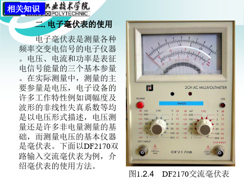
二.电子毫伏表的使用
电子毫伏表是测量各种 频率交变电信号的电子仪器 。电压、电流和功率是表征 电信号能量的三个基本参量 。在实际测量中,测量的主 要参量是电压,电子设备的 许多工作特性例如调幅度及 波形的非线性失真系数等均 是以电压形式描述,电压测 量还是许多非电量测量的基 础,而测量电压的基本仪器 是毫伏表。下面以DF2170双 路输入交流毫伏表为例,介 绍毫伏表的使用方法。
图1.2.4 DF2170交流毫伏表
DF2170B
电 子 毫 伏 表
表 头
•
机械零位调 整(黑针)
机械零位调 整(红针 )
电源开关 量程开关
电源指示灯
量程开 关通道输入通道输 入4,接通电源,按下电源开 关,发光二极管灯亮仪 器立刻工作。但为了保 证性能稳定可预热1min 后使用,开机后10秒钟 内指针无规则摆动数次 是正常的。
- 1、下载文档前请自行甄别文档内容的完整性,平台不提供额外的编辑、内容补充、找答案等附加服务。
- 2、"仅部分预览"的文档,不可在线预览部分如存在完整性等问题,可反馈申请退款(可完整预览的文档不适用该条件!)。
- 3、如文档侵犯您的权益,请联系客服反馈,我们会尽快为您处理(人工客服工作时间:9:00-18:30)。
1. 产品介绍 (1)
2. 使用前之注意事项 (2)
3. 面板介绍 (3)
4. 操作方法 (6)
5. 规格 (8)
6. 维护 (11)
ii
iii
安全术语与标示
以下各种安全标示可能会出现在这本操作手册或本产品上:
警告﹕表示产品在某一确认情况下或是在实际应用上之结果可能会对人体产生伤害甚至于造成生命之损失﹒
注意﹕表示产品在某一确认情况下或是在实际应用上之结果可能会对本产品或是其它产品造成损坏﹒
以下各种安全标示可能会出现在这本操作手册或本产品上:
危险﹕ 注意﹕
保护导电端子 接地端子 高电压
内容请参 考本手册
1. 产品介绍
GVT-417B为一个通用交流电压表, 可测量300uV~100V(10Hz ~ 1MHz)的交流电压.测量电压为1V时,相应分贝值为0dB.整个测量范围内,分贝值范围为-90dB~+41dB. 600Ω(1mW)dBm范围为
-90dBm~+43dBm.
仪器的刻度高达1.1(对应+1dB).此延长的刻度非常有利于音频放大器特性的测量.另外,满刻度时,仪器输出端子输出大约0.1V电压.如此可监控测量.
1
2. 使用前之注意事项
(1). 底座接地端
在连接电源之前,保证底座接地端接地.
(2). 最大输入电压
如果输入电压超过指定电压,会损坏该电压表. 指定电压由
输入讯号的峰值和叠加直流电压决定: 范围为0~300uV时, 最大输入电压为300V; 范围为3V~100V时, 最大输入电压为500V.
(3). 连接线
当测量讯号很低(例如300uV)或测量讯号源阻抗很高,输入线易受外部噪声影响.为了抑制噪音,根据噪声频率,选择屏蔽线或同轴线.
(4). 满刻度
GVT毫伏表采用一个延长的刻度,使读值范围大于传统的满刻度.
注意对于0 - 1.12 满刻度,1.0为额定值.红色标记
2
3
3. 面板介绍 (1) 表头
方便的电压和dB 读值. (2) 调零
机械式调零. (3) 档位选择开关
以10dB/档的衰减选择合适的电压文件位, 方便读值. (4) 输入接口
连接待测信号.
最大绝缘直流电压为 ±30V (峰值)
(5) 输出接口
当此仪表用作前置放大器,此接口输出信号.若档位选择开关打在100mV ,输出电压将大约等于输入信号. 若否,档位选择开关打在相邻的高档或低档时,放大因子减少或增加10dB.
最大绝缘直流电压为 ±12V(峰值) (6) 电源开关 (7) 电源指示灯 (8)
输入电源插座
4. 操作方法
A.电压测量
1. 关掉电源
2. 检查零点. 若有漂移, 用一个螺丝起子调整仪表前盖中央
的零点调节螺丝.
3. 将交流电源插头插入交流电源插座.
4. 设置档位到100V并打开电源.
5. 将测试线连到输入端口,开始测量.
6. 调整档位选择开关直到指针指在≧满刻度的1/3处,以方便
读值.
B. 分贝档位的应用
表盘上提供有两个分贝刻度,校准如下:
0dB = 1V
0dBm=0.775V(1mV,600Ω)
1.dB
“Bel”是计量功率比值的对数单位.一个分贝(“decibel”, 缩写为dB)为一个贝尔(Bel)的十分之一.
dB的定义如下:
dB = 10 log (P2 / P1)
若R1=R2, 功率比值可如下所示:
dB = 20log (E2/E1) = 20log (I2/I1)
dB的定义最初如上用以表示功率的比值. 但在应用中,其它值的比率(电压比或电流比)对数也可称为dB.
4
例如,一个放大器的输入电压为10mV,输出电压为10V,放大等级为10V/10mV=1000倍.此也可以dB为单位表示如下:
放大等级=20log (10V/10mV) = 60dB
2. dBm
“dBm”为dB(mW)的缩写.表示的是相对于1mW的功率比值.通常指的是600Ω阻抗下的功率.
因此, “0dBm”定义如下:
0dBm = 1mW 或0.775V 或1.291mA
3. 功率或电压的级别由刻度读值和选择的档位决定.
例如:
刻度读值檔位级别
(-1dB) + (+20dB) = +19dB
(+2dBm) + (+10dBm) = +12dBm
4. 显示表头的dB和dBm刻度如下:
5
5. 规格
6
7
*在输入公共端和底座间
8
9 6. 维护
6-1. 清洁
以温和的洗涤剂和清水沾湿柔软的布擦拭仪器。
不可以直接喷洒清洁剂到机器上,以防泄漏到机器内部而损坏机器。
不要使用含碳氢化合物或氯化物,或类似的溶剂,亦不可使用研磨的清洁剂。
6-2. 故障排除
GVT-417B 的故障排除仅限于检查输入电源保险丝.如果你有其它操作困难,请与固纬代理商联系.
警告:为避免电击,电源线的接地保护导体必须接到大地。
警告:为了确保有效的防火措施,只限于更换特定样式和额定值的保险丝。
更换前必须先切断电源,并将电源线从电源插座上取下来。