中英文文献翻译-起重机介绍
起重机文献翻译 高考翻译 机械翻译中英对照
起重机文献翻译高考翻译机械翻译国内双钩同步起吊电动葫芦发展综述Development Overview of Domestic Double-hook Synchronous Hoisting Electric Hoist于晓东1吴英年2Y u Xiaodong1Wu Yingnian2摘要:分析了国内生产的几种双钩同步电动葫芦结构与功能,重点介绍了HT型双钩同步电动葫芦的功能特点与应用,指出了产品研制应创新使其具有长远生命力。
Abstract:This paper analyzes the structures and functions of several domestic-made double-hook synchronous hoisting electric hoists, emphasizes the function and characteristics of HI type double-hook synchronous hoisting electric hoist and points out that product development should be innovative as to make long-term vitality.关键词:双钩同步电动葫芦;功能;结构;应用;发展Keywords: double-hook synchronous hoisting electric hoist; function; structure; application; development2.起重机用钢丝绳标准的选择Crane Wire Ropes Standard Selection陈立Chen Li3.斗轮堆取料机在头部激振下的动态响应Dynamic Response of Bucket Wheel Stacker Reclaimer underHead Shock Excitation王俊华张光宇高翔孔涛Wang Junhua Zhang Guangyu Gao Xiang Kong Tao摘要:分析斗轮堆取料机的实际工程特点,对其进行有限元建模并进行模态和谐响应分析,以了解斗轮堆取料机轮斗头部在滚筒或斗轮激振力作用下垂直方向的动态特性。
中英文翻译起重机发展史、分类及前景

毕业设计中英文翻译Crane history, classification and prospects起重机发展史、分类及前景Concept Crane (Crane) is a kind of lifting, Is a for loop Intermittent motion machinery. A work cycle, including: Extract plant extract to the items from the institute, Then move to the designated location lowered the level of items Then, the reverse movement, Back to extract device in situ for the next cycle.Usually by the crane hoisting mechanism (the items up and down movement), Operating agencies (the lifting movement), Luffing and slewing mechanism (the articles for the horizontal movement), Coupled with the metal body Power plant, Control and manipulation of a combination of the necessary auxiliary equipment. Type In the bridge used in the construction crane, According to its structure and properties of different Can be divided into light and small lifting equipment, Bridge type crane and jib type crane three categories. Small-sized lifting equipment such as: Jack, Gourd, Winch and so on. Such as the type of crane girder bridge cranes, Gantry cranes.Type of crane boom, such as fixed slewing cranes, Towercrane, Crane, Tires, Crawler cranes.Within a certain range to enhance the vertical and horizontal multi-action heavy lifting crane. Also known as the crane. Are material handlingmachinery. Crane's work is characterized by intermittent exercise to do, That is expected to take a work cycle, Migration, Unloading the corresponding body is alternately moves the work. Prototype crane Ancient Chinese irrigation of farmland is used orange prototype type cranes. The 14th century, Western Europe, human and animal-driven emergence of the rotation type cranes. Early 19th century, There bridge crane; Important wear parts such as crane shaft Spreader and other gear and began to use metal materials, and introducing the hydraulic drive. The late 19th century, Gradually replaced steam-driven crane crane with hydraulic drive. 20th century, 20's, the electrical industry and the rapid industrial development of internal combustion engines, To motor or internal combustion power plant basically formed of various cranes.Cranes include hoisting mechanism, Run institutions, Luffing, Slewing mechanism and metal structure. Crane hoisting mechanism is the basic working body Mostly formed by the hanging system and winch, Also lift heavy objects through the hydraulic system. Operating agencies to adjust the vertical or horizontal transport heavy cranes working position, Generally by the motor, Reducer, Brake and wheel components. Luffing jib crane in only with, the When looked up and boom amplitude and Bent over when the rate increases, Points amplitude balance both amplitude and non-equilibrium. Slewing mechanism for rotating the arm, By the drive and the rotary bearing device composition. Crane metal structure is the skeleton, Main bearing parts such as bridge, Arm and the door frame structure or for the box truss structure, but also for web structure, Some are available as supporting steel beams. Crane according to the structure of the different classification:Crane beam 1 Beam crane. Over a rectangular space in its operations, Used for workshops, Warehouse, Open yard loading and unloading of goods, etc., A beam crane, Crane, Gantrycranes, Crane, Carrying bridges.① beam crane: Beam cranes including single girder overhead crane and double girder overhead craneSingle girder overhead crane girder bridge of the word to use more steel or steel type and steel composite section. Crab often hand chain hoist, Hoist electric hoist or lifting mechanism as assembled parts.Supported by bridge type and the hanging of two. The former bridge crane beam along the orbit vehicles; The latter suspension bridge along the roof of the plant under the crane track. Single girder overhead crane points manually, Electric two. Manual single girder overhead crane operating speed of the lower body, Starting weight is also smaller, But their quality is small, Facilitate the organization of production, Low cost, When the power handling capacity fornon-small, Speed and productivity for less demanding applications.Manual Single-girder overhead crane with manual monorail car as a running car, Hand pull hoist as the lifting body Bridge from the main beam and side beams formed. Generally use the single main beam I-beam, End beam is bent shape with a steel or welded steel plate.Electric single girder overhead crane speed, Higher productivity than manual, From the weight as well. Electric single girder overhead crane by the bridge, Traveling mechanism, Electric hoist and electrical equipment components.② bridge crane:Overhead bridge crane is a bridge in the orbit of a bridge crane, Also known as the crane. The bridge crane lay along the elevated track in the vertical sides of runs Lifting trolley along the track laid on the bridge on the horizontal run The scope of work constitutes a rectangular, Can take full advantage of the space under the lifting bridge materials Ground equipment is not hindered.Bridge crane is widely used in indoor and outdoor storage, Plant, Pier and open storage yard, etc.. Overhead crane bridge crane can be divided into ordinary, simple beam bridge crane and metallurgical three special crane.General bridge crane lifting trolley generally, Bridge run institutions, Bridge the metal structures. Crab and the hoisting mechanism, Car run institutions and small frame of three parts.Lifting mechanism including motors, Brakes, Reducer, Reels and pulleys. Motor through reducer, Driven drum rotation, The rope around the drum or from the reel down, To lift heavy objects. Is supporting for small frame and installation of lifting the car to run institutions, agencies and chassis components, Usually welded structure.2 Cantilever crane (jib crane)Cantilever crane with high column, Wall, Three forms of balance crane.① is a cantilever crane cantilever column can be fixed around the column base fixed on the rotary, Column with the transfer or rigid cantilever, Together within the base support in the vertical center line of rotation relative to the columns and cantilever formed by the cantilever crane. It applies from the weight of small, Operating range of services to round or fan of the occasion. Generally used for machine tools and handling the workpiece chucking.Pillar jib cranes to use more electric chain hoist for lifting mechanism and operation of institutions, Less use of wire rope hoist and chain hoists. Rotation and horizontal movement to use more manual work, Only from the weight of the larger When using electric.② wall crane is secured to the wall on the cantilever crane, Or you can along the wall or other support structure on an elevated track running on the cantilever crane.Line where the wall using a crane to span a larger Large workshop building height or warehouse, Close to the wall near the lifting operation at the more frequent the most suitable. Multi-wall line and the top of the crane or bridge crane beam with the use of Near the wall at the service in a rectangular space, Responsible for the lifting of light and small objects, Large bridge crane from the beam or commitment.③ balance crane balance known as hoists, It is the principle of the use offour-bar linkage to balance the weight load and form a balanced system, Spreader using a variety of flexible and can easily load being lifted in the three-dimensional space. Balance crane lightweight and flexible, Is an ideal lifting small items of lifting equipment, Is widely used in factory floor machine loading and unloading, Process between Automatic line Production line of the workpiece, Sand box lifting, Parts assembly, And thestation, Terminals, Warehouse various occasions Crane organizationsdrive Can be divided into two main categories: One for focus driver That is driven by an electric motor on both sides of the active long-wheel shaft drive; The other for each driver, That is active on both sides of each wheel driven by an electric motor. In More frequent use of small crane brake, Gear and motor combined into one of the "triple play" Drive, From the weight of a large bridge crane for the general ease of installation and adjustment, Universal coupling drive is often used. Structure crane (crane) run institutions generally take the initiative and driven by four wheels, If the effect is very heavy, Commonly used methods to increase the wheel to reduce wheel pressure. When more than four wheels when Must be balanced with articulated frame device The crane's load evenly distributed throughout the wheel.Bridge's metal structure from the main beam and side beams composedof Divided into single-and dual-beam bridge girder bridge types. Single-girder bridge by a single span both sides of the main beam and in the end beam composition Double-beam bridge consists of two main beams and side beams formed.The main beam and side beams rigidly connected End beam at both ends with wheels, To support the elevated bridge in the running. The main beam welded track, For lifting the car running. Bridge girder type of structure more typical of a box structure, Four truss truss structure and fasting.Box structure can be divided into two-track box beams, Partial double-rail box beam, Partial rail box, such as several single main beam. Double-track box beam is widely used as a basic form From the main beam on Under both sides of the vertical flange and web components, Car rail arranged in the center of the flange on the line Its structure is simple, The convenience, Suitable for mass production, However, larger self.Partial double-rail box rail box beam and partial cross section of a single main beam are made on the Ranging from under the flange and web thickness of the main and auxiliary components, Arranged in the main web of rail carabove Cabinets can save short-stiffeners, One side rail box is a single main beam box girder flange width instead of two main beams, Weightless However, more complex manufacturing. Four from the four truss structure to form closed space plane truss structure Truss in the horizontal surface is paved walkway panels, light weight, Stiffness, But compared with other structures, Size large, Create more complex Lower fatigue strength, Have less production.Partial fasting truss structure similar to the rail box girder, Plate by the four form a closed structure, In addition to the main web is a real belly-section beams,the The remaining three pieces of steel plate cut into many windows in accordance with design requirements, The formation of a non-fasting truss diagonals, In the last, The surface of a horizontal truss walkway lined with boards, Crane agencies and electrical equipment installed in the bridge house, Lighter weight, Overall stiffness, This is a more widely used in China as a type.General bridge crane mainly electrically driven, Control room is usually the driver, There are remote control. From the weight of up to five hundred tons, Span of up to 60 meters.Simple beam bridge crane, also known as beam cranes, The structure and composition similar to ordinary bridge crane, Starting weight, Span and the pace of work are small.Bridge girder or other beam by beam and plate steel, consisting of a simple beam, Hand pull or electric hoist as the lifting hoist coupled with easy trolley car, the car is generally I-beam's bottom flange on the run. Bridge can be run along the elevated track, Can also be elevated along the suspension in the followingorbit This is called hanging beam crane cranes.Metallurgy crane in the steel production process to participate in a particular process operation, The basic structure and general overhead crane similar tothe However, lifting a small car is also equipped with a special working body or device. The cranes feature is the use of frequent Bad conditions High-level work. There are five types.Simple beam bridge crane type Casting crane Casting crane: For lifting hot metal into the mixer, Steel-making furnaces and the molten steel into a continuous ingot lifting equipment or ingot molds used. Master Sheng car lifting barrels, Sheng, deputy car to flip bucket and other auxiliary work.Tongs crane: Use tongs to heat ingot vertically lifted onto a soaking pit furnace, Or put it out into the car shipped spindles.Off ingot crane: Ingot from the ingot mold used in the extrusionforce. Small car off the tablets have a special device, Way off the ingot ingot mold according to the shape of the set: Some off the tablet press and hold the ingot rod Crane Yongxiang, Ingot mold with tongs lift; Some press and hold the ingot mold with tongs, Ingot with a small clamp lift.Charging crane: Added to the charge in the open hearth. Column with the bottom of the main car pick rod, And to stir it into the furnace hopper. The main column can turn around the vertical axis, Pick the rod can swing up and down and rotating. Vice-car heaters and other auxiliary operations for the repair.Forged Crane: Cooperation with the hydraulic press for forging a large workpiece. Special hook to hang the main car turned feeder, To support and flip the workpiece; Vice-car to lift the workpiece.Gantry cranes: bridge set the level of support legs form two gantry crane shape of a bridge. The crane on the ground orbit Mainly used in open storageyard, Dock, Power plants, Ports and railway stations and other places cargo handling and installation. Gantry crane hoisting mechanism, Car run institutions and bridge structures Basically the same with the bridge crane. The span, Crane bodies were driven mostly by way of To prevent the crane have skewing increased running resistance Even accidents. Gantry crane lifting trolley running on the bridge, Some crab is a type cranes. Bridge on both sides of the legs are generally rigid legs; Span of more than 30 meters, Side of the rigid legs often, While the other side of the bridge connection through the ball joints and flexible legs, The door frame to become statically determinate system, This prevents the outer lateral thrust loads caused by the additional stress Can also compensate for temperature deformation of vertical bridge gantry cranes wind area, to prevent thedecline in the strong wind lines or overturned, With wind instrument and with the operating agencies of the crane rail clamp interlock. Both ends of bridge can be no cantilever; Can also be one end or both ends of the cantilever cantilever, To extend the operating range. One end of a half bridge leg gantry crane, The other end without legs, Run directly on the high bench. Gantry cranes are divided into 4 types.① General gantry crane: The most versatile cranes, Can move into a variety of items and bulk materials, From the weight of 100 tons, a span of 4 to 35 meters. Common with the gantry crane grab a high-level work.② Hydropower Station Gantry Crane: mainly used for lifting and opening and closing gates, but also for the installation. 80 to 500 tons lifting capacity, small span, 8 to 16 meters; Lower lifting speed for 1 to 5 m / min. The lifting cranes, though not always, But once the work is very heavy use, So to improve the appropriate level.③ shipbuilding gantry crane: Berth assembly for the hull, Standing with two crab: There are two main hook one, Flange of the bridge on theorbit; Another has a main hook and a Vice-hook, In the bottom flange of the rail bridge run To flip and hoisting a large hull blocks. Weight is generally from 100 to 1500 tons; Span of 185 meters; Lifting speed of 2 to 15 m /min, There are 0.1 ~ 0.5 m / min micro speed.④ container gantry crane: For the container terminal. Trailer Bridge to Quay container carrying containers unloaded from the ship transported to the yard or the rear, by the stacking container gantry crane loading up or directly away, you can speed up the bridge or other crane container carrying turnover. Can be stacked high 3 to 4 layers 6 row wide container yard, General tire type, it also uses rail style. Container gantry cranes and container cross-car comparison The span and height of door frame on both sides of the larger. To meet the transportationneeds of the port, The higher level work crane. Lifting speed of 8 to 10 m / min; Across the span of the container needed to determine the number of rows, maximum of 60 meters corresponding to 20 feet, 30 feet, 40 feet long container from the weight of approximately 20 tons, 25 tons and 30 tons.④ carrying bridgeIncrease the span of the development by the gantry crane from a bridgecrane, Also known as the loading bridge. For open storage yard, Port and railway cargo terminals and other places. General delivery of large gantry crane bridge and a similar structure. Features are: ① mainly for handling large quantities of bulk materials; ② span, Generally more than 30meters, Some 170 meters; ③ jobs frequently, Highproductivity, Generally 500 to 1,500 tons / When Working speed is high, Lifting speed of 60 to 70 m / Points, Car speed is 100 ~ 350 m / Points, High-level work; ④ run institutions only carry the bridge to adjust the working position, Non-work institutions. When the span is large, The bridge of the bridge carrying on a rigid support legs and a flexible support legs. Bridge with two legs can be bolted connection; Connection with the flexible legs can also be ball joints or column joints, Relative to the flexible legs can have a range of skew bridge.Formed by the truss girder bridge, Crab in its winding rod or bottom chord of the track. Some cars with rotary boom, The equivalent of a run on the bridge type cranes.Container wharf in the port carrying the bridge is running, Is a special structure of large cranes, Dedicated to the ship's container handling work. Both sides of the generally rigid legs, The formation of a solid door frame, Bridge bearing fused with the door frame on the upper frame. With a container spreader (see cross-car) the car to run on the bridge. Long cantilever extending toward thesea is usually to pitch in. Non-operational state, Cantilever can be lifted at 80 °~ 85 °Elevation Department To carry over the bridge to the highest point on the ship. Operations cantilever flat. Also some cantilever is fixed.2. Double girder bridge craneDouble girder bridge crane from the straight track, Cranegirder, Crab, Power transmission systems and electrical controlsystem, Particularly suited to large hanging from the weight of the plane and large range of material handling.3 Type cranes. And over in the round ground operations, Used foropen-air loading and unloading and installation, etc., A crane, Floating cranes, Mast crane Wall line of cranes and deck cranes.4 Tower crane. Generally used in the site, Lifting supplies.5 Portal crane. Oh, generally used for the port. In addition, Cranes can also drive, Type of work, Mobility and use of such classification.Crane according to the different installation methods can be divided into:1 Truck Crane Truck CraneWill be installed in the general or special crane chassis of low disk performance is equivalent to the total weight of the truck the same vehicle, Meet the technical requirements for road vehicles, Thus the various types of road passage. Such cranes typically available on Off the two control rooms, Operations must be extended leg stable.Weight range from large, From 8 tons to 1,000 tons, Axle chassis number From 2 to 10. Is the largest output, The most widely used type of crane.2 Tire CraneLifting part of the pneumatic tire installed on a special cranechassis. Combined with an engine on and off, Speed is generally not more than 30KM / H, Vehicle width is wider, It is not appropriate long-distance driving on the highway. With no legs and hoists, traveling hoists features For the freight yard, Terminals, Move away from the site and other places with limited lifting operation.3 Off-road tire cranes are 70 developed a crane, Its function and tire hoist crane similar to Can also be carried out without legs and hoists, traveling hoists.The difference is the chassis structure and chassis by the unique structure brings improved driving performance. The engines are mounted on the crane chassis, the chassis has two axles and four large diameter off-road tire pattern. Four wheels are driving wheels and steering wheel, When the muddy uneven transfer station site, the Four wheels is transmitted power, The four-wheel drive, To improve through the muddy ground and uneven road ability. When the flat surface moving at a rapid pace, Front axle or rear axle with only two wheels driven To reduce energy consumption. Random file at the crane, Expressed by 4 × 4 wheel drive, 4 × 2, said four axles with two wheels in the wheel. The model for small venue work. Can achieve a continuous stepless variable speed, Resistance mutations in the case of the road will not turn off the engine, Thus a great convenience to the driver's operation. The off-road tires can be a performance extension of the crane, and Powerful and flexible tire crane.4 All Terrain CraneIs an off-road crane truck crane and both the characteristics of high performance products. It can not only transfer as fast as cranes, Long-distance travel, but also to meet in the narrow and bumpy or muddy field on the work request, The driving speed, Multi-bridge driver All-wheel steering, Three turnaround mode,ground clearance large High-climbing ability, No need for features such as lifting legs, Is a very promising product. But the price is higher, On the use and maintenance require a higher level.5 CraneA specific task to complete the development of special crane. For example: The implementation of tactical and technical safeguards to mechanized use, Off-road vehicles or armored personnel carriers mounted on the crane wheel rescue vehicle; To deal with road traffic accidents Wrecker, etc. Fall into this category.Crane Job Type: Refers to how busy the crane and load the parameters of degree of change.Busy work degree Crane for Means the total time in a year, The actual number of hours of crane operation and the ratio of total number of hours; Of institutions, Refers to an institution operating hours within a year and the ratio of total number of hours. In a working cycle of the crane, Agencies operating time percentage of Called the agency's duty cycle, By JC said.Degree of load changes, Designed by a crane rated capacity in actual operation, The load of the lifting crane is often less than the ratedcapacity. The degree of this change in load from the weight of the utilization factor k said. k = crane weight from the average of the actual year / crane's rated capacity.According cranes busy loading level and degree of change, Usually the type of cranes are: Light level, Intermediate, Heavy and Extra Heavy Grade 4 level.Cranes and lifting the types of work are two different concepts, Lifting capacity, May not be re-grade, From the weight of small, Not necessarilylight level. Such as hydropower capacity by the crane's lifting hundreds oftons, But the opportunity is rarely used, Only in the installation ofunits, When using the repair crew, Rest of the time stop there, So, although from very heavy, But still is light level. Another example is the use of the station yard gantry cranes, Although not from the weight, But the work is very busy Are heavy duty type of work.Crane safety performance of the types of work and has a very close relationship. Starting weight, Span The same crane lifting height, If the work of different types, In the design manufacture, Safety factor is not taken by the same That is, parts and components model, Size, Specifications vary. Such as wire rope, brake as a result of different types, Different safety factor (light-level security coefficient is small, Heavy duty safety factor) , The selected model is not the same. Then, as is the 10t bridge crane, For the intermediate type of work (JC = 25%) The lifting motor power N = 16KW, As for the heavy duty type of work (JC = 40%) Lifting motor power compared to N = 23. 5KW.From the above we can see that If the light level work crane type used in heavy duty type of work place Cranes will often faulty, Of safe production. Therefore, security checks, Crane should pay attention to the type of work and working conditions must be consistent.Crane characteristic curve: the carrying capacity of the crane structure, Boom lifting capacity and stability against overturning three whole envelope curve.Practice double girder bridge crane2.33. 1 Work agoa. On the brakes, Hook, Steel wire rope and safety devices and other components required by point inspection card check Abnormalphenomena Should be excluded.b. The operator must be sure to go when no one Taiwan, or track, Can close the main power supply. When the power circuit breaker or a sign on the lock when The people concerned should be removed before the original closing the main power supply. Crane safety devices which In order to ensure safe and reliable lifting operation, Crane with a better safety devices To accidental circumstances, Protects the device or to remind the operator attention To play a security role.1. Hydraulic system, the relief valve: Inhibit the abnormal high pressureloop, To prevent damage to hydraulic pumps and motors, And to prevent overload in the state.2. Luffing crane safety devices: When the unexpected incident occurs, Boom luffing cylinder high-pressure hose or loop or cut off when the pipeburst, Balancing valve in the hydraulic circuit to work, Lock chamber from the fuel tank of the work under the oil The boom will not fall To ensure job security.3. Telescopic crane safety devices: When the unexpected incidentoccurs, Telescopic boom cylinder high-pressure hose or loop or cut off when the pipe burst, Balancing valve in the hydraulic circuit to work, Lock chamber from the fuel tank of the work under the oil Retracted to hang on their own, To ensure job security.4. Height limit device: Rose from under hook height, Touch the limit hammer, Open limit switch, "over around" indicator light is bright, At the same time cut off the hook lifting, Boom out, V to the other movements the crane operation and ensure safety. Then as long as the manipulation of hookdrop Boom boom retracted or looked up (ie safe side operation) so thehandle, Lift the constraints that limit a heavy hammer, Returned to normal operation. For special occasions, If still needs to be over around the operation ofmicro, Press the release button on the meter box, The role of time limit will be lifted, But this time the operation must be very careful, In case something happensSo.5. Outrigger locking device: When the unexpected incident occurs, Leading to the leg vertical cylinder high-pressure hose or pipe rupture or cutting, Two-way hydraulic system hydraulic lock cylinder block to block the two legs of the pressureoil chamber, Indented or throw the legs, To ensure the safety of lifting operations.6. From the weight indicator: From the weight indicator set in the basic arm of the co-lateral side (right side of the control room), Control room operator can sit clearly observed, Can accurately indicate the condition of the crane, and the corresponding elevation to allow the rated capacity crane.7. Lifting characteristics table: In the control room set up under the siding on the front side, The table lists the various working range of arm length and rated under the weight and lifting height To operation inspection. Liftingoperations, Must not exceed the values specified in the table. In order to ensure safe and reliable lifting operation, Crane with a better safety devices To accidental circumstances, Protect or warn the operating personnel in mechanical, To play a security role.Lifting according to their functions and structural features of Can be divided into the following four categories.I. Small-sized lifting equipmentLight lifting equipment is characterized by a smalllight, Compact Movements are simple, Operating range projection of a point, Line-based. Light, Small lifting equipment, generally only one elevator, It only。
中英文文献翻译-起重机介绍

附录外文文献原文:The Introduction of cranesA crane is defined as a mechanism for lifting and lowering loads with a hoisting mechanism Shapiro, 1991. Cranes are the most useful and versatile piece of equipment on a vast majority of construction projects. They vary widely in configuration, capacity, mode of operation, intensity of utilization and cost. On a large project, a contractor may have an assortment of cranes for different purposes. Small mobile hydraulic cranes may be used for unloading materials from trucks and for small concrete placement operations, while larger crawler and tower cranes may be used for the erection and removal of forms, the installation of steel reinforcement, the placement of concrete, and the erection of structural steel and precast concrete beams.On many construction sites a crane is needed to lift loads such as concrete skips, reinforcement, and formwork. As the lifting needs of the construction industry have increased and diversified, a large number of general and special purpose cranes have been designed and manufactured. These cranes fall into two categories, those employed in industry and those employed in construction. The most common types of cranes used in construction are mobile, tower, and derrick cranes.1.Mobile cranesA mobile crane is a crane capable of moving under its own power without being restricted to predetermined travel. Mobility is provided by mounting or integrating the crane with trucks or all terrain carriers or rough terrain carriers or by providing crawlers. Truck-mounted cranes have the advantage of being able to move under their own power to the construction site. Additionally, mobile cranes can move about the site, and are often able to do the work of several stationary units.Mobile cranes are used for loading, mounting, carrying large loads and for work performed in the presence of obstacles of various kinds such as power lines and similar technological installations. The essential difficulty is here the swinging of the payload which occurs during working motion and also after the work is completed. This applies particularly to the slewing motion of the crane chassis, for which relatively large angular accelerations and negative accelerations of the chassis are characteristic. Inertia forces together with the centrifugal force and the Carioles force cause the payload to swing as a spherical pendulum. Proper control of the slewing motion of the crane serving to transport a payload to the defined point with simultaneous minimization of the swings when theworking motion is finished plays an important role in the model.Modern mobile cranes include the drive and the control systems. Control systems send the feedback signals from the mechanical structure to the drive systems. In general, they are closed chain mechanisms with flexible members [1].Rotation, load and boom hoisting are fundamental motions the mobile crane. During transfer of the load as well as at the end of the motion process, the motor drive forces, the structure inertia forces, the wind forces and the load inertia forces can result in substantial, undesired oscillations in crane. The structure inertia forces and the load inertia forces can be evaluated with numerical methods, such as the finite element method. However, the drive forces are difficult to describe. During start-up and breaking the output forces of the drive system significantly fluctuate. To reduce the speed variations during start-up and braking the controlled motor must produce torque other than constant [2,3], which in turn affects the performance of the crane.Modern mobile cranes that have been built till today have oft a maximal lifting capacity of 3000 tons and incorporate long booms. Crane structure and drive system must be safe, functionary and as light as possible. For economic and time reasons it is impossible to build prototypes for great cranes. Therefore, it is desirable to determinate the crane dynamic responses with the theoretical calculation.Several published articles on the dynamic responses of mobile crane are available in the open literature. In the mid-seventies Peeken et al. [4] have studied the dynamic forces of a mobile crane during rotation of the boom, using very few degrees of freedom for the dynamic equations and very simply spring-mass system for the crane structure. Later Maczynski et al. [5] studied the load swing of a mobile crane with a four mass-model for the crane structure. Posiadala et al. [6] have researched the lifted load motion with consideration for the change of rotating, booming and load hoisting. However, only the kinematics were studied. Later the influence of the flexibility of the support system on the load motion was investigated by the same author [7]. Recently, Kilicaslan et al. [1] have studied the characteristics of a mobile crane using a flexible multibody dynamics approach. Towarek [16] has concentrated the influence of flexible soil foundation on the dynamic stability of the boom crane. The drive forces, however, in all of those studies were presented by using so called the metho d of ……kinematics forcing‟‟ [6] with assumed velocities or accelerations. In practice this assumption could not comply with the motion during start-up and braking.A detailed and accurate model of a mobile crane can be achieved with the finite element method. Using non-linear finite element theory Gunthner and Kleeberger [9] studied the dynamic responses of lattice mobile cranes. About 2754 beam elements and 80 truss elements were used for modeling of the lattice-boom structure. On this basis a efficient software for mobile crane calculation––NODYA has been developed. However, the influences of the drive systems must be determined by measuring on hoisting of the load[10], or rotating of the crane [11]. This is neither efficient nor convenient for computer simulation of arbitrary crane motions.Studies on the problem of control for the dynamic response of rotary crane are also available. Sato et al. [14], derived a control law so that the transfer a load to a desired position will take place that at the end of the transfer of the swing of the load decays as soon as possible. Gustafsson [15] described a feedback control system for a rotary crane to move a cargo without oscillations and correctly align the cargo at the final position. However, only rigid bodies and elastic joint between the boom and the jib in those studies were considered. The dynamic response of the crane, for this reason, will be global.To improve this situation, a new method for dynamic calculation of mobile cranes will be presented in this paper. In this method, the flexible multibody model of the steel structure will be coupled with the model of the drive systems. In that way the elastic deformation, the rigid body motion of the structure and the dynamic behavior of the drive system can be determined with one integrated model. In this paper this method will be called ……complete dynamic calculation for driven “mechanism”.On the basis of flexible multibody theory and the Lagrangian equations, the system equations for complete dynamic calculation will be established. The drive- and control system will be described as differential equations. The complete system leads to a non-linear system of differential equations. The calculation method has been realized for a hydraulic mobile crane. In addition to the structural elements, the mathematical modeling of hydraulic drive- and control systems is decried. The simulations of crane rotations for arbitrary working conditions will be carried out. As result, a more exact representation of dynamic behavior not only for the crane structure, but also for the drive system will be achieved. Based on the results of these simulations the influences of the accelerations, velocities during start-up and braking of crane motions will be discussed.2.Tower cranesThe tower crane is a crane with a fixed vertical mast that is topped by a rotating boom and equipped with a winch for hoisting and lowering loads (Dickie, 990). Tower cranes are designed for situations which require operation in congested areas. Congestion may arise from the nature of the site or from the nature of the construction project. There is no limitation to the height of a high-rise building that can be constructed with a tower crane. The very high line speeds, up to 304.8 mrmin, available with some models yield good production rates at any height. They provide a considerable horizontal working radius, yet require a small work space on the ground (Chalabi, 1989). Some machines can also operate in winds of up to 72.4 km/h, which is far above mobile crane wind limits.The tower cranes are more economical only for longer term construction operations and higher lifting frequencies. This is because of the fairly extensive planning needed for installation, together with the transportation, erection and dismantling costs.3. Derrick cranesA derrick is a device for raising, lowering, and/or moving loads laterally. The simplest form of the derrick is called a Chicago boom and is usually installed by being mounted to building columns or frames during or after construction (Shapiro and Shapiro, 1991).This derrick arrangement. (i.e., Chicago boom) becomes a guy derrick when it is mounted to a mast and a stiff leg derrick when it is fixed to a frame.The selection of cranes is a central element of the life cycle of the project. Cranes must be selected to satisfy the requirements of the job. An appropriately selected crane contributes to the efficiency, timeliness, and profitability of the project. If the correct crane selection and configuration is not made, cost and safety implications might be created (Hanna, 1994). Decision to select a particular crane depends on many input parameters such as site conditions, cost, safety, and their variability. Many of these parameters are qualitative, and subjective judgments implicit in these terms cannot be directly incorporated into the classical decision making process. One way of selecting crane is achieved using fuzzy logic approach.Cranes are not merely the largest, the most conspicuous, and the most representative equipment of construction sites but also, at various stages of the project, a real “bottleneck” that slows the pace of the construction process. Although the crane can be found standing idle in many instances, yet once it is involved in a particular task ,it becomes an indispensable link in the activity chain, forcing at least two crews(in the loading and the unloading zones) to wait for the service. As analyzed in previous publications [6-8] it is feasible to automate (or, rather, semi-automate) crane navigation in order to achieve higher productivity, better economy, and safe operation. It is necessary to focus on the technical aspects of the conversion of existing crane into large semi-automatic manipulators. By mainly external devices mounted on the crane, it becomes capable of learning, memorizing, and autonomously navigation to reprogrammed targets or through prêt aught paths.The following sections describe various facets of crane automation:First, the necessary components and their technical characteristics are reviewed, along with some selection criteria. These are followed by installation and integration of the new components into an existing crane. Next, the Man –Machine –Interface (MMI) is presented with the different modes of operation it provides. Finally, the highlights of a set of controlled tests are reported followed by conclusions and recommendations.Manual versus automatic operation: The three major degrees of freedom of common tower cranes are illustrated in the picture. In some cases , the crane is mounted on tracks , which provide a fourth degree of freedom , while in other cases the tower is “telescope” or extendable , and /or the “jib” can be raised to a diagonal position. Since these additional degrees of freedom are not used routinely during normal operation but rather are fixed in a certain position for long periods (days or weeks), they are not included in the routineautomatic mode of operation, although their position must be “known” to the control system.外文文献中文翻译:起重机介绍起重机是用来举升机构、抬起或放下货物的器械。
起重机中英文对照外文翻译文献

起重机中英⽂对照外⽂翻译⽂献中英⽂对照外⽂翻译(⽂档含英⽂原⽂和中⽂翻译)Control of Tower Cranes WithDouble-Pendulum Payload DynamicsAbstract:The usefulness of cranes is limited because the payload is supported by an overhead suspension cable that allows oscilation to occur during crane motion. Under certain conditions, the payload dynamics may introduce an additional oscillatory mode that creates a double pendulum. This paper presents an analysis of this effect on tower cranes. This paper also reviews a command generation technique to suppress the oscillatory dynamics with robustness to frequency changes. Experimental results are presented to verify that the proposed method can improve the ability of crane operators to drive a double-pendulum tower crane. The performance improvements occurred during both local and teleoperated control.Key words:Crane , input shaping , tower crane oscillation , vibrationI. INTRODUCTIONThe study of crane dynamics and advanced control methods has received significant attention. Cranes can roughly be divided into three categories based upontheir primary dynamic properties and the coordinate system that most naturally describes the location of the suspension cable connection point. The first category, bridge cranes, operate in Cartesian space, as shown in Fig. 1(a). The trolley moves along a bridge, whose motion is perpendicular to that of the trolley. Bridge cranes that can travel on a mobile base are often called gantry cranes. Bridge cranes are common in factories, warehouses, and shipyards.The second major category of cranes is boom cranes, such as the one sketched in Fig. 1(b). Boom cranes are best described in spherical coordinates, where a boom rotates aboutaxes both perpendicular and parallel to the ground. In Fig. 1(b), ψis the rotation aboutthe vertical, Z-axis, and θis the rotation about the horizontal, Y -axis. The payload is supported from a suspension cable at the end of the boom. Boom cranes are often placed on a mobile base that allows them to change their workspace.The third major category of cranes is tower cranes, like the one sketched in Fig. 1(c). These are most naturally described by cylindrical coordinates. A horizontal jib arm rotates around a vertical tower. The payload is supported by a cable from the trolley, which moves radially along the jib arm. Tower cranes are commonly used in the construction of multistory buildings and have the advantage of having a small footprint-to-workspace ratio. Primary disadvantages of tower and boom cranes, from a control design viewpoint, are the nonlinear dynamics due to the rotational nature of the cranes, in addition to the less intuitive natural coordinate systems.A common characteristic among all cranes is that the pay- load is supported via an overhead suspension cable. While this provides the hoisting functionality of the crane, it also presents several challenges, the primary of which is payload oscillation. Motion of the crane will often lead to large payload oscillations. These payload oscillations have many detrimental effects including degrading payload positioning accuracy, increasing task completion time, and decreasing safety. A large research effort has been directed at reducing oscillations. An overview of these efforts in crane control, concentrating mainly on feedback methods, is provided in [1]. Some researchers have proposed smooth commands to reduce excitation of system flexible modes [2]–[5]. Crane control methods based on command shaping are reviewed in [6]. Many researchers have focused on feedback methods, which necessitate the addition necessitate the addition of sensors to the crane and can prove difficult to use in conjunction with human operators. For example, some quayside cranes have been equipped with sophisticated feedback control systems to dampen payload sway. However, the motions induced by the computer control annoyed some of the human operators. As a result, the human operators disabled the feedback controllers. Given that the vast majority of cranes are driven by human operators and will never be equipped with computer-based feedback, feedback methods are not considered in this paper.Input shaping [7], [8] is one control method that dramatically reduces payload oscillation by intelligently shaping the commands generated by human operators [9], [10]. Using rough estimates of system natural frequencies and damping ratios, a series of impulses, called the input shaper, is designed. The convolution of the input shaper and the original command is then used to drive the system. This process is demonstrated with atwo-impulse input shaper and a step command in Fig. 2. Note that the rise time of the command is increased by the duration of the input shaper. This small increase in the rise time isnormally on the order of 0.5–1 periods of the dominant vibration mode.Fig. 1. Sketches of (a) bridge crane, (b) boom crane, (c) and tower crane.Fig. 2. Input-shaping process.Input shaping has been successfully implemented on many vibratory systems including bridge [11]–[13], tower [14]–[16], and boom [17], [18] cranes, coordinate measurement machines[19]–[21], robotic arms [8], [22], [23], demining robots [24], and micro-milling machines [25].Most input-shaping techniques are based upon linear system theory. However, some research efforts have examined the extension of input shaping to nonlinear systems [26], [14]. Input shapers that are effective despite system nonlinearities have been developed. These include input shapers for nonlinear actuator dynamics, friction, and dynamic nonlinearities [14], [27]–[31]. One method of dealing with nonlinearities is the use of adaptive or learning input shapers [32]–[34].Despite these efforts, the simplest and most common way to address system nonlinearities is to utilize a robust input shaper [35]. An input shaper that is more robust to changes in system parameters will generally be more robust to system nonlinearities that manifest themselves as changes in the linearized frequencies. In addition to designing robust shapers, input shapers can also be designed to suppress multiple modes of vibration [36]–[38].In Section II, the mobile tower crane used during experimental tests for this paper is presented. In Section III, planar and 3-D models of a tower crane are examined to highlight important dynamic effects. Section IV presents a method to design multimode input shapers with specified levels of robustness. InSection V, these methods are implemented on a tower crane with double-pendulum payload dynamics. Finally, in Section VI, the effect of the robust shapers on human operator performance is presented for both local and teleoperated control.II. MOBILE TOWER CRANEThe mobile tower crane, shown in Fig. 3, has teleoperation capabilities that allow it to be operated in real-time from anywhere in the world via the Internet [15]. The tower portion of the crane, shown in Fig. 3(a), is approximately 2 m tall with a 1 m jib arm. It is actuated by Siemens synchronous, AC servomotors. The jib is capable of 340°rotation about the tower. The trolley moves radially along the jib via a lead screw, and a hoisting motor controls the suspension cable length. Motor encoders are used for PD feedback control of trolley motion in the slewing and radial directions. A Siemens digital camera is mounted to the trolley and records the swing deflection of the hook at a sampling rate of 50 Hz [15].The measurement resolution of the camera depends on the suspension cable length. For the cable lengths used in this research, the resolution is approximately 0.08°. This is equivalent to a 1.4 mm hook displacement at a cable length of 1 m. In this work, the camera is not used for feedback control of the payload oscillation. The experimental results presented in this paper utilize encoder data to describe jib and trolley position and camera data to measure the deflection angles of the hook. Base mobility is provided by DC motors with omnidirectional wheels attached to each support leg, as shown in Fig. 3(b). The base is under PD control using two HiBot SH2-based microcontrollers, with feedback from motor-shaft-mounted encoders. The mobile base was kept stationary during all experiments presented in this paper. Therefore, the mobile tower crane operated as a standard tower crane.Table I summarizes the performance characteristics of the tower crane. It should be noted that most of these limits areenforced via software and are not the physical limitations of the system. These limitations are enforced to more closely match theoperational parameters of full-sized tower cranes.Fig. 3. Mobile, portable tower crane, (a) mobile tower crane, (b) mobile crane base.TABLE I MOBILE TOWER CRANE PERFORMANCE LIMITSFig. 4 Sketch of tower crane with a double-pendulum dynamics.III. TOWER CRANE MODELFig.4 shows a sketch of a tower crane with a double-pendulum payload configuration. The jib rotates by an angle around the vertical axis Z parallelto the tower column. The trolley moves radially along the jib; its position along the jib is described by r . The suspension cable length from the trolley to the hook is represented by an inflexible, massless cable of variable length 1l . The payload is connected to the hook via an inflexible, massless cable of length 2l . Both the hook and the payload are represented as point masses having masses h m and p m , respectively.The angles describing the position of the hook are shown in Fig. 5(a). The angle φrepresents a deflection in the radial direction, along the jib. The angle χ represents a tangential deflection, perpendicular to the jib. In Fig. 5(a), φ is in the plane of the page, and χ lies in a plane out of the page. The angles describing the payload position are shown in Fig. 5(b). Notice that these angles are defined relative to a line from the trolley to the hook. If there is no deflection of the hook, then the angleγ describes radial deflections, along the jib, and the angle α represents deflections perpendicular to the jib, in the tangential direction. The equations of motion for this model were derived using a commercial dynamics package, but they are too complex to show in their entirety here, as they are each over a page in length.To give some insight into the double-pendulum model, the position of the hook and payload within the Newtonian frame XYZ are written as —h q and —p q , respectivelyWhere -I , -J and -K are unit vectors in the X , Y , and Z directions. The Lagrangian may then be written asFig. 5. (a) Angles describing hook motion. (b) Angles describing payload motion.Fig. 6. Experimental and simulated responses of radial motion.(a) Hook responses (φ) for m 48.01=l ,(b) Hook responses for m 28.11=lThe motion of the trolley can be represented in terms of the system inputs. The position of the trolley —tr q in the Newtonian frame is described byThis position, or its derivatives, can be used as the input to any number of models of a spherical double-pendulum. More detailed discussion of the dynamics of spherical double pendulums can be found in [39]–[42].The addition of the second mass and resulting double-pendulum dramatically increases the complexity of the equations of motion beyond the more commonly used single-pendulum tower model [1], [16], [43]–[46]. This fact can been seen in the Lagrangian. In (3), the terms in the square brackets represent those that remain for the single-pendulum model; no —p q terms appear. This significantly reduces the complexity of the equations because —p q is a function of the inputs and all four angles shown in Fig. 5.It should be reiterated that such a complex dynamic model is not used to design the input-shaping controllers presented in later sections. The model was developed as a vehicle to evaluate the proposed control method over a variety of operating conditions and demonstrate its effectiveness. The controller is designed using a much simpler, planar model.A. Experimental V erification of the ModelThe full, nonlinear equations of motion were experimentally verified using several test cases. Fig.6 shows two cases involving only radial motion. The trolley was driven at maximum velocity for a distance of 0.30 m, with 2l =0.45m .The payload mass p m for both cases was 0.15 kg and the hook mass h m was approximately 0.105 kg. The two cases shown in Fig. 6 present extremes of suspension cable lengths 1l . In Fig. 6(a), 1l is 0.48 m , close to the minimum length that can be measured by the overhead camera. At this length, the double-pendulum effect is immediately noticeable. One can see that the experimental and simulated responses closely match. In Fig. 6(b), 1l is 1.28 m, the maximum length possible while keeping the payload from hitting the ground. At this length, the second mode of oscillation has much less effect on the response. The model closely matches the experimental response for this case as well. The responses for a linearized, planar model, which will be developed in Section III-B, are also shown in Fig. 6. The responses from this planar model closely match both the experimental results and the responses of the full, nonlinear model for both suspension cable lengths.Fig. 7. Hook responses to 20°jib rotation:(a) φ (radial) response;(b) χ (tangential) response.Fig. 8. Hook responses to 90°jib rotation:φ(radial) response;(b) χ(tangential) response.(a)If the trolley position is held constant and the jib is rotated, then the rotational and centripetal accelerations cause oscillation in both the radial and tangential directions. This can be seen in the simulation responses from the full nonlinear model in Figs. 7 and 8. In Fig. 7, the trolley is held at a fixed position of r = 0.75 m, while the jib is rotated 20°. This relatively small rotation only slightly excites oscillation in the radial direction, as shown in Fig. 7(a). The vibratory dynamics are dominated byoscillations in the tangential direction, χ, as shown in Fig. 7(b). If, however, a large angular displacement of the jib occurs, then significant oscillation will occur in both the radial and tangential directions, as shown in Fig. 8. In this case, the trolley was fixed at r = 0.75 m and the jib was rotated 90°. Figs. 7 and 8 show that the experimental responses closely match those predicted by the model for these rotational motions. Part of the deviation in Fig. 8(b) can be attributed to the unevenness of the floor on which the crane sits. After the 90°jib rotation the hook and payload oscillate about a slightly different equilibrium point, as measured by the overhead camera.Fig.9.Planardouble-pendulummodel.B.Dynamic AnalysisIf the motion of the tower crane is limited to trolley motion, like the responses shown in Fig. 6, then the model may be simplified to that shown in Fig. 9. This model simplifies the analysis of the system dynamics and provides simple estimates of the two natural frequencies of the double pendulum. These estimates will be used to develop input shapers for the double-pendulum tower crane.The crane is moved by applying a force )(t u to the trolley. A cable of length 1l hangs below the trolley and supports a hook, of mass h m , to which the payload is attached using rigging cables. The rigging and payload are modeled as a second cable, of length 2l and point mass p m . Assuming that the cable and rigging lengths do not change during the motion, the linearized equations of motion, assuming zero initial conditions, arewhere φ and γ describe the angles of the two pendulums, R is the ratio of the payload mass to the hook mass, and g is the acceleration due to gravity.The linearized frequencies of the double-pendulum dynamics modeled in (5) are [47]Where Note that the frequencies depend on the two cable lengths and the mass ratio.Fig. 10. Variation of first and second mode frequencies when m l l 8.121=+.。
起重机的历史外文文献翻译、中英文翻译

The History of Crane1.OverviewThe first construction cranes were invented by the Ancient Greeks and were powered by men or beasts of burden, such as donkeys. These cranes were used for the construction of tall buildings. Larger cranes were later developed, employing the use of human treadwheels, permitting the lifting of heavier weights. In the High Middle Ages, harbor cranes were introduced to load and unload ships and assist with their construction – some were built into stone towers for extra strength and stability. The earliest cranes were constructed from wood, but cast iron and steel took over with the coming of the Industrial Revolution.For many centuries, power was supplied by the physical exertion of men or animals, although hoists in watermills and windmills could be driven by the harnessed natural power. The first 'mechanical' power was provided by steam engines, the earliest steam crane being introduced in the 18th or 19th century, with many remaining in use well into the late 20th century. Modern cranes usually use internal combustion engines or electric motors and hydraulic systems to provide a much greater lifting capability than was previously possible, although manual cranes are still utilized where the provision of power would be uneconomic.Cranes exist in an enormous variety of forms – each tailored to a specific use. Sizes range from the smallest jib cranes, used inside workshops, to the tallest tower cranes, used for constructing high buildings. For a while, mini - cranes are also used for constructing high buildings, in order to facilitate constructions by reaching tight spaces. Finally, we can find larger floating cranes, generally used to build oil rigs and salvage sunken ships. This article also covers lifting machines that do not strictly fit the above definition of a crane, but are generally known as cranes, such as stacker cranes and loader cranes.2. History(1)Ancient GreeceThe crane for lifting heavy loads was invented by the Ancient Greeks in the late 6th century BC. The archaeological record shows that no later than c.515 BC distinctive cuttings for both lifting tongs and lewis irons begin to appear on stone blocks of Greek temples. Since these holes point at the use of a lifting device, and since they are to be found either above the center of gravity of the block, or in pairs equidistant from a point over the center of gravity, they are regarded by archaeologists as the positive evidence required for the existence of the crane.The introduction of the winch and pulley hoist soon lead to a widespread replacement of ramps as the main means of vertical motion. For the next two hundred years, Greek building sites witnessed a sharp drop in the weights handled, as the new lifting technique made the use of several smaller stones more practical than of fewer larger ones. In contrast to the archaic period with its tendency to ever-increasing block sizes, Greek temples of the classical age like the Parthenon invariably featured stone blocks weighing less than 15-20 tons. Also, the practice of erecting large monolithic columns was practically abandoned in favor of using several column drums.Although the exact circumstances of the shift from the ramp to the crane technology remain unclear, it has been argued that the volatile social and political conditions of Greece were moresuitable to the employment of small, professional construction teams than of large bodies of unskilled labor, making the crane more preferable to the Greek polis than the more labor-intensive ramp which had been the norm in the autocratic societies of Egypt or Assyria.The first unequivocal literary evidence for the existence of the compound pulley system appears in the Mechanical Problems (Mech. 18, 853a32-853b13) attributed to Aristotle (384-322 BC), but perhaps composed at a slightly later date. Around the same time, block sizes at Greek temples began to match their archaic predecessors again, indicating that the more sophisticated compound pulley must have found its way to Greek construction sites by then.Ancient RomeThe heyday of the crane in ancient times came during the Roman Empire, when construction activity soared and buildings reached enormous dimensions. The Romans adopted the Greek crane and developed it further. We are relatively well informed about their lifting techniques, thanks to rather lengthy accounts by the engineers Vitruvius (De Architectura 10.2, 1-10) and Heron of Alexandria (Mechanica 3.2-5). There are also two surviving reliefs of Roman treadwheel cranes, with the Haterii tombstone from the late first century AD being particularly detailed.The simplest Roman crane, the Trispastos, consisted of a single-beam jib, a winch, a rope, and a block containing three pulleys. Having thus a mechanical advantage of 3:1, it has been calculated that a single man working the winch could raise 150 kg (3 pulleys x 50 kg = 150), assuming that 50 kg represent the maximum effort a man can exert over a longer time period. Heavier crane types featured five pulleys (Pentaspastos) or, in case of the largest one, a set of three by five pulleys (Polyspastos) and came with two, three or four masts, depending on the maximum load. The Polyspastos, when worked by four men at both sides of the winch, could already lift 3000 kg (3 ropes x 5 pulleys x 4 men x 50 kg = 3000 kg). In case the winch was replaced by a treadwheel, the maximum load even doubled to 6000 kg at only half the crew, since the treadwheel possesses a much bigger mechanical advantage due to its larger diameter. This meant that, in comparison to the construction of the Egyptian Pyramids, where about 50 men were needed to move a 2.5 ton stone block up the ramp (50 kg per person), the lifting capability of the Roman Polyspastos proved to be 60 times higher (3000 kg per person).However, numerous extant Roman buildings which feature much heavier stone blocks than those handled by the Polyspastos indicate that the overall lifting capability of the Romans went far beyond that of any single crane. At the temple of Jupiter at Baalbek, for instance, the architrave blocks weigh up to 60 tons each, and one corner cornice block even over 100 tons, all of them raised to a height of about 19 m. In Rome, the capital block of Trajan's Column weighs 53.3 tons, which had to be lifted to a height of about 34 m (see construction of Trajan's Column).It is assumed that Roman engineers lifted these extraordinary weights by two measures (see picture below for comparable Renaissance technique): First, as suggested by Heron, a lifting tower was set up, whose four masts were arranged in the shape of a quadrangle with parallel sides, not unlike a siege tower, but with the column in the middle of the structure (Mechanica 3.5). Second, a multitude of capstans were placed on the ground around the tower, for, although having a lower leverage ratio than treadwheels, capstans could be set up in higher numbers and run by more men (and, moreover, by draught animals). This use of multiple capstans is also described by AmmianusMarcellinus (17.4.15) in connection with the lifting of the Lateranense obelisk in the Circus Maximus (ca. 357 AD). The maximum lifting capability of a single capstan can be established by the number of lewis iron holes bored into the monolith. In case of the Baalbek architrave blocks, which weigh between 55 and 60 tons, eight extant holes suggest an allowance of 7.5 ton per lewis iron, that is per capstan. Lifting such heavy weights in a concerted action required a great amount of coordination between the work groups applying the force to the capstans.Middle AgesDuring the High Middle Ages, the treadwheel crane was reintroduced on a large scale after the technology had fallen into disuse in western Europe with the demise of the Western Roman Empire. The earliest reference to a treadwheel (magna rota) reappears in archival literature in France about 1225, followed by an illuminated depiction in a manuscript of probably also French origin dating to 1240. In navigation, the earliest uses of harbor cranes are documented for Utrecht in 1244, Antwerp in 1263, Brugge in 1288 and Hamburg in 1291, while in England the treadwheel is not recorded before 1331.Generally, vertical transport could be done more safely and inexpensively by cranes than by customary methods. Typical areas of application were harbors, mines, and, in particular, building sites where the treadwheel crane played a pivotal role in the construction of the lofty Gothic cathedrals. Nevertheless, both archival and pictorial sources of the time suggest that newly introduced machines like treadwheels or wheelbarrows did not completely replace more labor-intensive methods like ladders, hods and handbarrows. Rather, old and new machinery continued to coexist on medieval construction sites and harbors.Apart from treadwheels, medieval depictions also show cranes to be powered manually by windlasses with radiating spokes, cranks and by the 15th century also by windlasses shaped like a ship's wheel. To smooth out irregularities of impulse and get over 'dead-spots' in the lifting process flywheels are known to be in use as early as 1123.The exact process by which the treadwheel crane was reintroduced is not recorded, although its return to construction sites has undoubtedly to be viewed in close connection with the simultaneous rise of Gothic architecture. The reappearance of the treadwheel crane may have resulted from a technological development of the windlass from which the treadwheel structurally and mechanically evolved. Alternatively, the medieval treadwheel may represent a deliberate reinvention of its Roman counterpart drawn from Vitruvius' De architectura which was available in many monastic libraries. Its reintroduction may have been inspired, as well, by the observation of the labor-saving qualities of the waterwheel with which early treadwheels shared many structural similarities.Structure and placementThe medieval treadwheel was a large wooden wheel turning around a central shaft with a treadway wide enough for two workers walking side by side. While the earlier 'compass-arm' wheel had spokes directly driven into the central shaft, the more advanced 'clasp-arm' type featured arms arranged as chords to the wheel rim, giving the possibility of using a thinner shaft and providing thus a greater mechanical advantage.Contrary to a popularly held belief, cranes on medieval building sites were neither placed on the extremely lightweight scaffolding used at the time nor on the thin walls of the Gothic churches which were incapable of supporting the weight of both hoisting machine and load. Rather, cranes were placed in the initial stages of construction on the ground, often within the building. When a new floor was completed, and massive tie beams of the roof connected the walls, the crane was dismantled and reassembled on the roof beams from where it was moved from bay to bay during construction of the vaults. Thus, the crane ‘grew’ and ‘wandered’ with the building with the result that today all extant construction cranes in England are found in church towers above the vaulting and below the roof, where they remained after building construction for bringing material for repairs aloft.Less frequently, medieval illuminations also show cranes mounted on the outside of walls with the stand of the machine secured to putlogs.Mechanics and operationIn contrast to modern cranes, medieval cranes and hoists - much like their counterparts in Greece and Rome - were primarily capable of a vertical lift, and not used to move loads for a considerable distance horizontally as well. Accordingly, lifting work was organized at the workplace in a different way than today. In building construction, for example, it is assumed that the crane lifted the stone blocks either from the bottom directly into place, or from a place opposite the centre of the wall from where it could deliver the blocks for two teams working at each end of the wall. Additionally, the crane master who usually gave orders at the treadwheel workers from outside the crane was able to manipulate the movement laterally by a small rope attached to the load. Slewing cranes which allowed a rotation of the load and were thus particularly suited for dockside work appeared as early as 1340. While ashlar blocks were directly lifted by sling, lewis or devil's clamp (German Teufelskralle), other objects were placed before in containers like pallets, baskets, wooden boxes or barrels.It is noteworthy that medieval cranes rarely featured ratchets or brakes to forestall the load from running backward. This curious absence is explained by the high friction force exercised by medieval treadwheels which normally prevented the wheel from accelerating beyond control. Harbor usageAccording to the "present state of knowledge" unknown in antiquity, stationary harbor cranes are considered a new development of the Middle Ages. The typical harbor crane was a pivoting structure equipped with double treadwheels. These cranes were placed docksides for the loading and unloading of cargo where they replaced or complemented older lifting methods like see-saws, winches and yards.Two different types of harbor cranes can be identified with a varying geographical distribution: While gantry cranes which pivoted on a central vertical axle were commonly found at the Flemish and Dutch coastside, German sea and inland harbors typically featured tower cranes where the windlass and treadwheels were situated in a solid tower with only jib arm and roof rotating. Interestingly, dockside cranes were not adopted in the Mediterranean region and the highly developed Italian ports where authorities continued to rely on the more labor-intensive method ofunloading goods by ramps beyond the Middle Ages.Unlike construction cranes where the work speed was determined by the relatively slow progress of the masons, harbor cranes usually featured double treadwheels to speed up loading. The two treadwheels whose diameter is estimated to be 4 m or larger were attached to each side of the axle and rotated together. Today, according to one survey, fifteen treadwheel harbor cranes from pre-industrial times are still extant throughout Europe.[28] Beside these stationary cranes, floating cranes which could be flexibly deployed in the whole port basin came into use by the 14th century.RenaissanceA lifting tower similar to that of the ancient Romans was used to great effect by the Renaissance architect Domenico Fontana in 1586 to relocate the 361 t heavy Vatican obelisk in Rome. From his report, it becomes obvious that the coordination of the lift between the various pulling teams required a considerable amount of concentration and discipline, since, if the force was not applied evenly, the excessive stress on the ropes would make them rupture.Early modern ageCranes were used domestically in the 17th and 18th century. The chimney or fireplace crane was used to swing pots and kettles over the fire and the height was adjusted by a trammel.4. Types of the cranesMobileMain article: Mobile craneThe most basic type of mobile crane consists of a truss or telescopic boom mounted on a mobile platform - be it on road, rail or water.FixedExchanging mobility for the ability to carry greater loads and reach greater heights due to increased stability, these types of cranes are characterized that they, or at least their main structure does not move during the period of use. However, many can still be assembled and disassembled.外文翻译起重机的历史1. 概况第一台具有机械结构的起重机是由古希腊人发明的,并且由人或者是牲畜比如驴,作为动力源。
起重机的历史外文文献翻译、中英文翻译
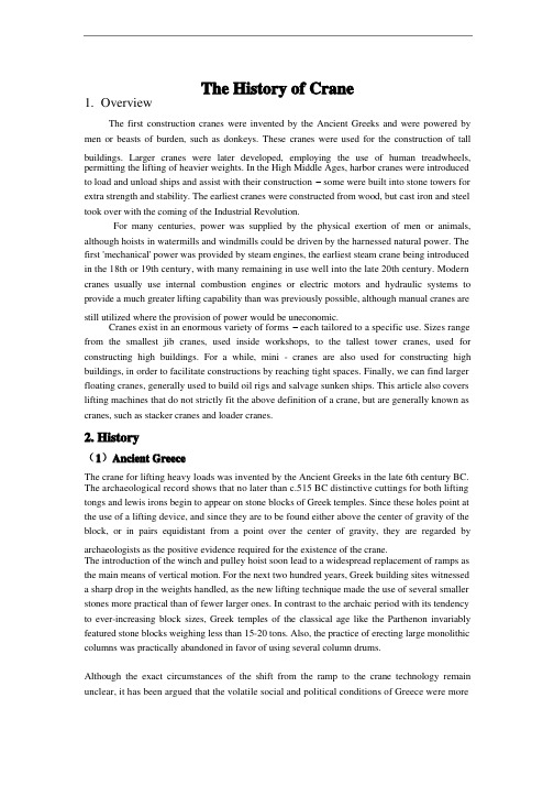
The History of Crane1. OverviewThe first construction cranes were invented by the Ancient Greeks and were powered by men or beasts of burden, such as donkeys. These cranes were used for the construction of tall buildings. Larger cranes were later developed, employing the use of human treadwheels, permitting the lifting of heavier weights. In the High Middle Ages, harbor cranes were introducedto load and unload ships and assist with their construction – some were built into stone towers for extra strength and stability. The earliest cranes were constructed from wood, but cast iron and steel took over with the coming of the Industrial Revolution.For many centuries, power was supplied by the physical exertion of men or animals, although hoists in watermills and windmills could be driven by the harnessed natural power. The first 'mechanical' power was provided by steam engines, the earliest steam crane being introducedin the 18th or 19th century, with many remaining in use well into the late 20th century. Modern cranes usually use internal combustion engines or electric motors and hydraulic systems to provide a much greater lifting capability than was previously possible, although manual cranes are still utilized where the provision of power would be uneconomic.Cranes exist in an enormous variety of forms – each tailored to a specific use. Sizes range from the smallest jib cranes, used inside workshops, to the tallest tower cranes, used for constructing high buildings. For a while, mini - cranes are also used for constructing high buildings, in order to facilitate constructions by reaching tight spaces. Finally, we can find larger floating cranes, generally used to build oil rigs and salvage sunken ships. This article also covers lifting machines that do not strictly fit the above definition of a crane, but are generally known as cranes, such as stacker cranes and loader cranes.2. History(1)Ancient GreeceThe crane for lifting heavy loads was invented by the Ancient Greeks in the late 6th century BC. The archaeological record shows that no later than c.515 BC distinctive cuttings for both lifting tongs and lewis irons begin to appear on stone blocks of Greek temples. Since these holes point at the use of a lifting device, and since they are to be found either above the center of gravity of the block, or in pairs equidistant from a point over the center of gravity, they are regarded by archaeologists as the positive evidence required for the existence of the crane.The introduction of the winch and pulley hoist soon lead to a widespread replacement of ramps as the main means of vertical motion. For the next two hundred years, Greek building sites witnesseda sharp drop in the weights handled, as the new lifting technique made the use of several smaller stones more practical than of fewer larger ones. In contrast to the archaic period with its tendencyto ever-increasing block sizes, Greek temples of the classical age like the Parthenon invariably featured stone blocks weighing less than 15-20 tons. Also, the practice of erecting large monolithic columns was practically abandoned in favor of using several column drums.Although the exact circumstances of the shift from the ramp to the crane technology remain unclear, it has been argued that the volatile social and political conditions of Greece were moresuitable to the employment of small, professional construction teams than of large bodies of unskilled labor, making the crane more preferable to the Greek polis than the more labor-intensive ramp which had been the norm in the autocratic societies of Egypt or Assyria.The first unequivocal literary evidence for the existence of the compound pulley system appears in the Mechanical Problems (Mech. 18, 853a32-853b13) attributed to Aristotle (384-322 BC), but perhaps composed at a slightly later date. Around the same time, block sizes at Greek temples began to match their archaic predecessors again, indicating that the more sophisticated compound pulley must have found its way to Greek construction sites by then.Ancient RomeThe heyday of the crane in ancient times came during the Roman Empire, when construction activity soared and buildings reached enormous dimensions. The Romans adopted the Greek crane and developed it further. We are relatively well informed about their lifting techniques, thanks to rather lengthy accounts by the engineers Vitruvius (De Architectura 10.2, 1-10) and Heron of Alexandria (Mechanica 3.2-5). There are also two surviving reliefs of Roman treadwheel cranes, with the Haterii tombstone from the late first century AD being particularly detailed.The simplest Roman crane, the Trispastos, consisted of a single-beam jib, a winch, a rope, and a block containing three pulleys. Having thus a mechanical advantage of 3:1, it has been calculated that a single man working the winch could raise 150 kg (3 pulleys x 50 kg = 150), assuming that 50 kg represent the maximum effort a man can exert over a longer time period. Heavier crane types featured five pulleys (Pentaspastos) or, in case of the largest one, a set of three by five pulleys (Polyspastos) and came with two, three or four masts, depending on the maximum load. The Polyspastos, when worked by four men at both sides of the winch, could already lift 3000 kg (3 ropes x 5 pulleys x 4 men x 50 kg = 3000 kg). In case the winch was replaced by a treadwheel, the maximum load even doubled to 6000 kg at only half the crew, since the treadwheel possesses a much bigger mechanical advantage due to its larger diameter. This meant that, in comparison to the construction of the Egyptian Pyramids, where about 50 men were needed to move a 2.5 ton stone block up the ramp (50 kg per person), the lifting capability of the Roman Polyspastos proved to be 60 times higher (3000 kg per person).However, numerous extant Roman buildings which feature much heavier stone blocks than those handled by the Polyspastos indicate that the overall lifting capability of the Romans went far beyond that of any single crane. At the temple of Jupiter at Baalbek, for instance, the architrave blocks weigh up to 60 tons each, and one corner cornice block even over 100 tons, all of them raised to a height of about 19 m. In Rome, the capital block of Trajan's Column weighs 53.3 tons, which had to be lifted to a height of about 34 m (see construction of Trajan's Column).It is assumed that Roman engineers lifted these extraordinary weights by two measures (see picture below for comparable Renaissance technique): First, as suggested by Heron, a lifting tower was set up, whose four masts were arranged in the shape of a quadrangle with parallel sides, not unlike a siege tower, but with the column in the middle of the structure (Mechanica 3.5). Second, a multitude of capstans were placed on the ground around the tower, for, although having a lower leverage ratio than treadwheels, capstans could be set up in higher numbers and run by more men (and, moreover, by draught animals). This use of multiple capstans is also described by AmmianusMarcellinus (17.4.15) in connection with the lifting of the Lateranense obelisk in the Circus Maximus (ca. 357 AD). The maximum lifting capability of a single capstan can be established by the number of lewis iron holes bored into the monolith. In case of the Baalbek architrave blocks, which weigh between 55 and 60 tons, eight extant holes suggest an allowance of 7.5 ton per lewis iron, that is per capstan. Lifting such heavy weights in a concerted action required a great amount of coordination between the work groups applying the force to the capstans.Middle AgesDuring the High Middle Ages, the treadwheel crane was reintroduced on a large scale after the technology had fallen into disuse in western Europe with the demise of the Western Roman Empire. The earliest reference to a treadwheel (magna rota) reappears in archival literature in France about 1225, followed by an illuminated depiction in a manuscript of probably also French origin dating to 1240. In navigation, the earliest uses of harbor cranes are documented for Utrecht in 1244, Antwerp in 1263, Brugge in 1288 and Hamburg in 1291, while in England the treadwheel is not recorded before 1331.Generally, vertical transport could be done more safely and inexpensively by cranes than by customary methods. Typical areas of application were harbors, mines, and, in particular, building sites where the treadwheel crane played a pivotal role in the construction of the lofty Gothic cathedrals. Nevertheless, both archival and pictorial sources of the time suggest that newly introduced machines like treadwheels or wheelbarrows did not completely replace more labor-intensive methods like ladders, hods and handbarrows. Rather, old and new machinery continued to coexist on medieval construction sites and harbors.Apart from treadwheels, medieval depictions also show cranes to be powered manually by windlasses with radiating spokes, cranks and by the 15th century also by windlasses shaped like a ship's wheel. To smooth out irregularities of impulse and get over 'dead-spots' in the lifting process flywheels are known to be in use as early as 1123.The exact process by which the treadwheel crane was reintroduced is not recorded, although its return to construction sites has undoubtedly to be viewed in close connection with the simultaneous rise of Gothic architecture. The reappearance of the treadwheel crane may have resulted from a technological development of the windlass from which the treadwheel structurally and mechanically evolved. Alternatively, the medieval treadwheel may represent a deliberate reinvention of its Roman counterpart drawn from Vitruvius' De architectura which was available in many monastic libraries. Its reintroduction may have been inspired, as well, by the observation of the labor-saving qualities of the waterwheel with which early treadwheels shared many structural similarities.Structure and placementThe medieval treadwheel was a large wooden wheel turning around a central shaft with a treadway wide enough for two workers walking side by side. While the earlier 'compass-arm' wheel had spokes directly driven into the central shaft, the more advanced 'clasp-arm' type featured arms arranged as chords to the wheel rim, giving the possibility of using a thinner shaft and providing thus a greater mechanical advantage.Contrary to a popularly held belief, cranes on medieval building sites were neither placed on the extremely lightweight scaffolding used at the time nor on the thin walls of the Gothic churches which were incapable of supporting the weight of both hoisting machine and load. Rather, cranes were placed in the initial stages of construction on the ground, often within the building. When a new floor was completed, and massive tie beams of the roof connected the walls, the crane was dismantled and reassembled on the roof beams from where it was moved from bay to bay during construction of the vaults. Thus, the crane ‘grew’ and ‘wandered’ with the building with the result that today all extant construction cranes in England are found in church towers above the vaulting and below the roof, where they remained after building construction for bringing material for repairs aloft.Less frequently, medieval illuminations also show cranes mounted on the outside of walls with the stand of the machine secured to putlogs.Mechanics and operationIn contrast to modern cranes, medieval cranes and hoists - much like their counterparts in Greece and Rome - were primarily capable of a vertical lift, and not used to move loads for a considerable distance horizontally as well. Accordingly, lifting work was organized at the workplace in a different way than today. In building construction, for example, it is assumed that the crane lifted the stone blocks either from the bottom directly into place, or from a place opposite the centre of the wall from where it could deliver the blocks for two teams working at each end of the wall. Additionally, the crane master who usually gave orders at the treadwheel workers from outside the crane was able to manipulate the movement laterally by a small rope attached to the load. Slewing cranes which allowed a rotation of the load and were thus particularly suited for dockside work appeared as early as 1340. While ashlar blocks were directly lifted by sling, lewis or devil's clamp (German Teufelskralle), other objects were placed before in containers like pallets, baskets, wooden boxes or barrels.It is noteworthy that medieval cranes rarely featured ratchets or brakes to forestall the load from running backward. This curious absence is explained by the high friction force exercised by medieval treadwheels which normally prevented the wheel from accelerating beyond control. Harbor usageAccording to the "present state of knowledge" unknown in antiquity, stationary harbor cranes are considered a new development of the Middle Ages. The typical harbor crane was a pivoting structure equipped with double treadwheels. These cranes were placed docksides for the loading and unloading of cargo where they replaced or complemented older lifting methods like see-saws, winches and yards.Two different types of harbor cranes can be identified with a varying geographical distribution: While gantry cranes which pivoted on a central vertical axle were commonly found at the Flemish and Dutch coastside, German sea and inland harbors typically featured tower cranes where the windlass and treadwheels were situated in a solid tower with only jib arm and roof rotating. Interestingly, dockside cranes were not adopted in the Mediterranean region and the highly developed Italian ports where authorities continued to rely on the more labor-intensive method ofunloading goods by ramps beyond the Middle Ages.Unlike construction cranes where the work speed was determined by the relatively slow progressof the masons, harbor cranes usually featured double treadwheels to speed up loading. The two treadwheels whose diameter is estimated to be 4 m or larger were attached to each side of the axle and rotated together. Today, according to one survey, fifteen treadwheel harbor cranes from pre-industrial times are still extant throughout Europe.[28] Beside these stationary cranes, floating cranes which could be flexibly deployed in the whole port basin came into use by the 14th century.RenaissanceA lifting tower similar to that of the ancient Romans was used to great effect by the Renaissance architect Domenico Fontana in 1586 to relocate the 361 t heavy Vatican obelisk in Rome. From his report, it becomes obvious that the coordination of the lift between the various pulling teams required a considerable amount of concentration and discipline, since, if the force was not applied evenly, the excessive stress on the ropes would make them rupture.Early modern ageCranes were used domestically in the 17th and 18th century. The chimney or fireplace crane was used to swing pots and kettles over the fire and the height was adjusted by a trammel.4. Types of the cranesMobileMain article: Mobile craneThe most basic type of mobile crane consists of a truss or telescopic boom mounted on a mobile platform - be it on road, rail or water.FixedExchanging mobility for the ability to carry greater loads and reach greater heights due to increased stability, these types of cranes are characterized that they, or at least their main structure does not move during the period of use. However, many can still be assembled and disassembled.外文翻译起重机的历史1. 概况第一台具有机械结构的起重机是由古希腊人发明的,并且由人或者是牲畜比如驴,作为动力源。
汽车起重机液压系统中英文对照外文翻译文献

汽车起重机液压系统中英文对照外文翻译文献(文档含英文原文和中文翻译)翻译:汽车式起重机液压系统—技术现状与发展趋势一、行业背景(一)国外工程汽车起重机的发展趋势近20年世界工程起重机行业发生了很大变化。
RT(越野轮胎起重机)和AT(全地面起重机)产品的迅速发展,打破了原有产品与市场格局,在经济发展及市场激烈竞争冲击下,导致世界市场进一步趋向一体化。
为与RT和AT产品抗衡,汽车起重机新技术、新产品也在不断发展。
近年来汽车起重机在英、美等国市场的复兴,使人们对汽车起重机产生新的认识。
几年前某些工业界人士曾预测,RT 和AT产品的兴起将导致汽车起重机的衰退。
日本汽车起重机在世界各地日益流行,以及最近格鲁夫、特雷克斯、林克.贝尔特、德马泰克等公司汽车起重机的产品进展,已向上述观念提出挑战。
随着工程起重机各机种间技术的相互渗透与竞争,汽车起重机会在世界市场中继续占有一席之地。
国外工程起重机从整体情况分析,领先国内10~20年(不同类型产品有所不同)。
随着国外经济发展速度趋于平稳,工程起重机向智能、高性能、灵活、适应性强、多功能方向发展。
25t以下基本上不生产,产品向高附加值、大吨位发展,住友建机、多田野和加藤公司曾于1989年相继推出360t汽车起重机。
住友建机在90年代开发出80t~250t共4种AT产品。
多田野也在90年代相继推出100t~550t共6种特大型AT产品。
加藤公司则研制成NK5000型500t汽车起重机。
行业配套也与国内有所不同:1、下车主要是300kW以上柴油大功率发动机,与之配套的液力变矩器和自动换档变速箱、12吨级驱动转向桥及越野轮胎。
2、上车:高强度材料、大扭矩的起升机构、回转机构、回转支承。
3、液压系统:变量泵、变量马达、电磁换向先导阀及主阀、平衡阀、悬挂系统阀、液压锁、液压缸及管路标准配套件。
4、智能控制系统:力限器显示控制、记忆通讯及单缸顺序伸缩自动控制。
(二)国内工程汽车起重机的发展趋势国内工程机械产品近十年来随着技术的引进、消化、吸收,有了长足的进步,产品性能、可靠性、外观都有较大幅度的提高,但同国外工程机械比较来看,还存在较大差距。
英文翻译外文文献翻译117港口起重机

英文翻译外文文献翻译117港口起重机附录APortal powerChina’s rapid economic growth in the past decade has resulted in a big increase in freight traffic through the country’s seaports . Old ports are being expanded and new ports built to handle the large growth in container and bulk cargo traffic all along the Chinese coastline.China’s port expansion programme has provided a strong boost to the domestic port equipment industry, which has enjoyed a strong increase in demand for port cranes of various types, including container cranes and portal cranes along with bulk cargo handling equipment.State-run China Harbour Engineering (group) Corporation Ltd, established under the ruling State Council, is China’s largest supplier of port cranes and bulk cargohandling equipment. The organization controls both Shanghai Zhenhua Port Machinery Co Ltd (ZPMC),the world’s largest manufacturer of quayside container cranes, and Shanghai Port Machinery Plant (SPMP), which specializes in the manufacturer of portal cranes and other cranes used in ports along with dry bulk cargo handling equipment.SPMP’s main market is China, although the company is looking to expand its overseas sales. Although less well known than its associate ZPMC, SPMP also operates large manufacturing facilities, and is due tomove part of its production shortly to Changxing Island near Shanghai where ZPMC already operates a large container crane fabrication plant.Portal and other harbour cranes are SPMP’s major production item. During thepast two years, the corporation has won contracts for 145 portal cranes from port authorities throughout China, both from new ports under construction and ports undergoing expansion.In recent years, SPMP has also supplied portal cranes to the United States, Iraq,and Myanmar.The port Rangoon of Myanmar in has purchased a 47m,40t portalcrane while BIW of the United States has purchased three cranes-15t,150t, and 300t portal cranes. Elsewhere, SPMP has supplied 12 portal cranes to several ports in Iraq since the end of the Saddam regime.In China, SPMP’s recent major orders for portal cranes includeeight 40t, 45m radius cranes for Tianjin Overseas Mineral Terminal, while Yan Tai Port Bureau in Guangdong in southern China has purchased six 40t, 45m radius cranes. Other large orders include seven 10t, 25m radius cranes for Zhenjiang Port Group and an order of 1025t, 33m radius cranes from Fangcheng Port Bureau, while the Yingkou Port Group has ordered 1325t,35m radius cranes along with two 40t, 44m radius port cranes.MANY CRANES BUILT TO ORDERSPMP also supplies other cranes used in ports and harbours, many of which are built to order for clients. Quayside container cranes havebeen supplied to a number of foreign clients including Bangkok Port in Thailand, Kaohsiung Port in Taiwan, and Port of Vancouver in Canada. In China, SPMP has supplied quayside container cranes to Shanghai Port, Tianjin Port, Yin Kou Port, Yan Tai Port and others. The company also supplies rubber-tyred container gantry cranes to domestic and overseas clients. Customers for other cranes used in ports include Guangzhou Port in Guangdong, which purchased a 25t floating crane while Zhonggang Port has bought two double trolley 125/63t gantry cranes, along with a700t overhead crane, In 2003 Zhonggang Port awarded a contract to SPMP for a 2,600t floating crane, whichi is the largest crane the company has made in recent years.Other customers include Zhongyuan Nanytong Shipyard of Jiangsu Province has purchased two 300t goliath cranes for use in its shipyard, while S hanghai Waigaoqiao Shipyard uses two of SPMP’s 600t goliath cranes for its shipbuilding operations. SPMP has two factories. The Shanghai plant employs 2,000 workers while a factory in Jiangsu Province employs 1,500 workers. The combined total of 3,500 workers includes 800 technical and management staff involved in designing, developing, and building portal and other cranes along with dry bulk cargo loading and unloading equipment.Currently, SPMP is preparing to vacate its Shanghai factory site as the comp any’sexisting plot of land is part of a riverside area earmarked by the Shanghai Expo in 2010. SPMP’s Shanghai factory will close at the end of 2006, and move to a new site on nearby Changxing Island.“The new factory will be much bigger than the present plant,” Li said. “Phase 1 will be ready for us when we move at the end of 2006.”In addition to moving the Shanghai factory to a new site, SPMP expects future business operation with ZPMC.Officials at China Harbour Engineering (Group) Corporation are understood to have told SPMP of plants for SPMP and ZPMC to co-operate more in bidding for projects in future. Both companies are expected to retain their individual manufacturing capability, however, with precise details of future co-operation still some way from being finalised.Meanwhile, SPMP associate company ZPMC is strengthening its position as the world’s largest manufacturer of ship-to-shore container cranes, supplying slightlymore than half the annual international container crane market. In addition to operating four crane production complexes for its crane manufacturing and other businesses.ZPMC’s full range of products includes quayside container cranes, rubber-tyredgantry cranes, bulk material ship loaders and unloaders, bucket-wheel stackers and reclaimers, portal cranes, floating cranes, and engineering vessels. The company has also diversified into manufacturing other large steel structures including large steel bridges.ZPMC EXPANDING PRODUCTIONZPMC’s cranes and other products are in use at over 150 shipping terminals in 37 countries and regions worldwide. By the end of December 2005, ZPMC had supplied 705 quayside container cranes, and had orders in hand to deliver another 128 quayside container cranes in 2006. In addition, at the end of 2005 ZPMC had delivered 1,148 rubber-tyred gantry cranes to customers worldwide and had orders in hand to deliver 308 rubber-tyred gantry cranes to customers in 2006.ZPMC is expanding production facilities in expectation that the volume of orders will grow in future. The company owns four crane production complexes in Shanghai and the surrounding area at Jiangyin, Changzhou, Zhangjiang and Changxing Island. The Changxing production site, which was completed in 2001, covers one million sq m, and has a 3.5km coastline. The facility is capable of manufacturing 160 quayside ship-to-shore container cranes each year along with 300 rubber-tyred gantry cranes and 200,000 metric tons of large steel bridge structures. Plans call for a futher 3 million sq m of land to be reclaimed at Changxing, which ZPMC will develop to become its largest production centre.Korea looks inward In a fragmented global port crane industry, Korean manufacturers are being forced to look for more business in their domestic marketsSouth Korea’s container crane and port crane equipment manufacturing industry has become more focused on the domestic market inrecent years as manufacturers have faced tough price competition from ZPMC of China in major foreign markets. The problem is the same as that faced by other port crane manufacturers around the world, none of which account for more than about an 8% share of the world container crane market.As well as ZPMC, competition from European and Japanese equipment suppliers is also strong, both for quayside container cranes and for rubber-tyred gantry crane contracts. While South Korean firms-including Hyundai Heavy Industries, Samsung Heavy Industries, Doosan Heavy Industries, and Hanjin Heavy Industries – continueto bid for international contracts, winning large orders has become increasingly rare.Doosan Heavy Industries & Construction Co Ltd is believed to be the only South Korean port crane maker to have won a large container crane contract during the past few years, with most orders booker by Korean manufacturers being for less than10 crane units.Doosan recently completed delivery of a 42-unit rubber-tyred gantry crane (RTGC) order to the Port of Singapore Authority PSN that was awarded in 2004. Including a recent contract. Doosan has received orders to supply the Port of Singapore with a total of 120 RTGCs since 1997. The recent batch of RTGCs is designed for increased safety. Esch of the RTGCs is fitted with 16 wheels instead of the usual eight.“We have supplied container crane s locally and overseas. Most projects are one or two units, but Singapore has been 120 units,” commented a source in Doosan Heavy Industries’ material handling equipment division. “Container cranes can lift one ortwo containers depending on the client, but the twin spreader design is normal now. Our biggest contract before was with Pusan Port for over 10 container cranes.”BUILDING POWER PLANTSDoosan Heavy Industries’ major activities include the design and construction ofpower plants. Apart from supplying protection equipment, Doosan also manufactures turbines and generator sets. Doosan has a large castings and forging division. Other major activities include the construction of desalination plants in the Middle East.Container port handling equipme nt is produced by Doosan’s material handling equipment division, which supplies coal handling equipment and bulk cargo handling facilities for other industries.Port of Singapore Authority is the largest customer for RTGCs. Other recent clients include Southern Gateway Terminals in Colombo, Sri Lanka, and Korea Express in the Port of Pusan.Doosan also supplies ship to shore container cranes. Recent quayside gantry crane clients include Jakarta Container Terminal in Indonesia, Jawaharlal Nehru Port near Mumbai in India, and Frazer Terminal in Vancouver.“Prospects for our port crane sales are not bright. ZPMC is dominating the world market due to price,” the source commented. “We are looking for projects notinvoving ZPMC as they are not concerned with all projects. We got contracts inSingapore in 2004 and 2005. We had no success anywhere else, but we are still bidding on various tenders.”Doosan is expected to be one of the bidders for container cranes to be installed in South Korea’s planned Kwangyan g Bay Port expansion. The company’s R&D division is involved developing new automated controls that will be required for quayside container cranes installed in the port expansion.“Container cranes are well developed in technical terms. There is nothing e lse to develop except for automation,” the source said. “We are developing more automated controls, but the new features are not commercialized yet.Our government has a plan for Kwangyang Bay 3-2 terminal project, which they announced will be developed as an automated terminal. We have to adapt to this. The tender has been postponed for about six years. We expect the project will be tendered again in 2007 or 2008.”South Korea’s other container crane manufacturers also are expected to bid for the Kwangyang Bay project, which is likely to be awarded to a local supplier. Hyundal Samho Heavy Industries will be among the bidders having recently commissioned five automated rail mounted gantry cranes(RMGCs) also known as automated transfer cranes at Pusan East Container Terminal (PECT) .The terminal has become the first terminal in Korea to install automated cranes, which are in service at new berths four and five .The cranes stack nine-wide between a 28.5m rail gauge, and have dual cantilevers covering two road lanes . Stack height is 1 over 6 by 9ft6in high and operational speeds are 150m/min for the gantry , 120m/min for the trolley and 75-80m/min for the empty hoist .Among other recent orders that Hyundai has won is a contract for four quayside container cranes from Hutchison Port Holdings and one for Uam Port.Competition from ZPMC remains the main challenge in winning overseas contracts according to Hyundai Heavy Industries sales manager Lee Yong Tae : “ We are trying to get more projects , but ZPMC has a very low price . We will try to cut our price but we think it will lead to a bad situation in future . ”“ if customers think that quality is important then we are ok , but if they just think about price we cannot win the project . We have experience of building cranes to liftone or two containers .We buy the main crane controls system from ABB and then use a Korean fabricator .”附录B港口起重机中国经济在过去的高速增长已经大幅增加了本国港口货流量,以至于不断扩大老港口以及不断修建新的港口以应对快速增长的集装箱业务以及大宗货物的流通。
- 1、下载文档前请自行甄别文档内容的完整性,平台不提供额外的编辑、内容补充、找答案等附加服务。
- 2、"仅部分预览"的文档,不可在线预览部分如存在完整性等问题,可反馈申请退款(可完整预览的文档不适用该条件!)。
- 3、如文档侵犯您的权益,请联系客服反馈,我们会尽快为您处理(人工客服工作时间:9:00-18:30)。
附录外文文献原文:The Introduction of cranesA crane is defined as a mechanism for lifting and lowering loads with a hoisting mechanism Shapiro, 1991. Cranes are the most useful and versatile piece of equipment on a vast majority of construction projects. They vary widely in configuration, capacity, mode of operation, intensity of utilization and cost. On a large project, a contractor may have an assortment of cranes for different purposes. Small mobile hydraulic cranes may be used for unloading materials from trucks and for small concrete placement operations, while larger crawler and tower cranes may be used for the erection and removal of forms, the installation of steel reinforcement, the placement of concrete, and the erection of structural steel and precast concrete beams.On many construction sites a crane is needed to lift loads such as concrete skips, reinforcement, and formwork. As the lifting needs of the construction industry have increased and diversified, a large number of general and special purpose cranes have been designed and manufactured. These cranes fall into two categories, those employed in industry and those employed in construction. The most common types of cranes used in construction are mobile, tower, and derrick cranes.1.Mobile cranesA mobile crane is a crane capable of moving under its own power without being restricted to predetermined travel. Mobility is provided by mounting or integrating the crane with trucks or all terrain carriers or rough terrain carriers or by providing crawlers. Truck-mounted cranes have the advantage of being able to move under their own power to the construction site. Additionally, mobile cranes can move about the site, and are often able to do the work of several stationary units.Mobile cranes are used for loading, mounting, carrying large loads and for work performed in the presence of obstacles of various kinds such as power lines and similar technological installations. The essential difficulty is here the swinging of the payload which occurs during working motion and also after the work is completed. This applies particularly to the slewing motion of the crane chassis, for which relatively large angular accelerations and negative accelerations of the chassis are characteristic. Inertia forces together with the centrifugal force and the Carioles force cause the payload to swing as a spherical pendulum. Proper control of the slewing motion of the crane serving to transport a payload to the defined point with simultaneous minimization of the swings when theworking motion is finished plays an important role in the model.Modern mobile cranes include the drive and the control systems. Control systems send the feedback signals from the mechanical structure to the drive systems. In general, they are closed chain mechanisms with flexible members [1].Rotation, load and boom hoisting are fundamental motions the mobile crane. During transfer of the load as well as at the end of the motion process, the motor drive forces, the structure inertia forces, the wind forces and the load inertia forces can result in substantial, undesired oscillations in crane. The structure inertia forces and the load inertia forces can be evaluated with numerical methods, such as the finite element method. However, the drive forces are difficult to describe. During start-up and breaking the output forces of the drive system significantly fluctuate. To reduce the speed variations during start-up and braking the controlled motor must produce torque other than constant [2,3], which in turn affects the performance of the crane.Modern mobile cranes that have been built till today have oft a maximal lifting capacity of 3000 tons and incorporate long booms. Crane structure and drive system must be safe, functionary and as light as possible. For economic and time reasons it is impossible to build prototypes for great cranes. Therefore, it is desirable to determinate the crane dynamic responses with the theoretical calculation.Several published articles on the dynamic responses of mobile crane are available in the open literature. In the mid-seventies Peeken et al. [4] have studied the dynamic forces of a mobile crane during rotation of the boom, using very few degrees of freedom for the dynamic equations and very simply spring-mass system for the crane structure. Later Maczynski et al. [5] studied the load swing of a mobile crane with a four mass-model for the crane structure. Posiadala et al. [6] have researched the lifted load motion with consideration for the change of rotating, booming and load hoisting. However, only the kinematics were studied. Later the influence of the flexibility of the support system on the load motion was investigated by the same author [7]. Recently, Kilicaslan et al. [1] have studied the characteristics of a mobile crane using a flexible multibody dynamics approach. Towarek [16] has concentrated the influence of flexible soil foundation on the dynamic stability of the boom crane. The drive forces, however, in all of those studies were presented by using so called the metho d of ……kinematics forcing‟‟ [6] with assumed velocities or accelerations. In practice this assumption could not comply with the motion during start-up and braking.A detailed and accurate model of a mobile crane can be achieved with the finite element method. Using non-linear finite element theory Gunthner and Kleeberger [9] studied the dynamic responses of lattice mobile cranes. About 2754 beam elements and 80 truss elements were used for modeling of the lattice-boom structure. On this basis a efficient software for mobile crane calculation––NODYA has been developed. However, the influences of the drive systems must be determined by measuring on hoisting of the load[10], or rotating of the crane [11]. This is neither efficient nor convenient for computer simulation of arbitrary crane motions.Studies on the problem of control for the dynamic response of rotary crane are also available. Sato et al. [14], derived a control law so that the transfer a load to a desired position will take place that at the end of the transfer of the swing of the load decays as soon as possible. Gustafsson [15] described a feedback control system for a rotary crane to move a cargo without oscillations and correctly align the cargo at the final position. However, only rigid bodies and elastic joint between the boom and the jib in those studies were considered. The dynamic response of the crane, for this reason, will be global.To improve this situation, a new method for dynamic calculation of mobile cranes will be presented in this paper. In this method, the flexible multibody model of the steel structure will be coupled with the model of the drive systems. In that way the elastic deformation, the rigid body motion of the structure and the dynamic behavior of the drive system can be determined with one integrated model. In this paper this method will be called ……complete dynamic calculation for driven “mechanism”.On the basis of flexible multibody theory and the Lagrangian equations, the system equations for complete dynamic calculation will be established. The drive- and control system will be described as differential equations. The complete system leads to a non-linear system of differential equations. The calculation method has been realized for a hydraulic mobile crane. In addition to the structural elements, the mathematical modeling of hydraulic drive- and control systems is decried. The simulations of crane rotations for arbitrary working conditions will be carried out. As result, a more exact representation of dynamic behavior not only for the crane structure, but also for the drive system will be achieved. Based on the results of these simulations the influences of the accelerations, velocities during start-up and braking of crane motions will be discussed.2.Tower cranesThe tower crane is a crane with a fixed vertical mast that is topped by a rotating boom and equipped with a winch for hoisting and lowering loads (Dickie, 990). Tower cranes are designed for situations which require operation in congested areas. Congestion may arise from the nature of the site or from the nature of the construction project. There is no limitation to the height of a high-rise building that can be constructed with a tower crane. The very high line speeds, up to 304.8 mrmin, available with some models yield good production rates at any height. They provide a considerable horizontal working radius, yet require a small work space on the ground (Chalabi, 1989). Some machines can also operate in winds of up to 72.4 km/h, which is far above mobile crane wind limits.The tower cranes are more economical only for longer term construction operations and higher lifting frequencies. This is because of the fairly extensive planning needed for installation, together with the transportation, erection and dismantling costs.3. Derrick cranesA derrick is a device for raising, lowering, and/or moving loads laterally. The simplest form of the derrick is called a Chicago boom and is usually installed by being mounted to building columns or frames during or after construction (Shapiro and Shapiro, 1991).This derrick arrangement. (i.e., Chicago boom) becomes a guy derrick when it is mounted to a mast and a stiff leg derrick when it is fixed to a frame.The selection of cranes is a central element of the life cycle of the project. Cranes must be selected to satisfy the requirements of the job. An appropriately selected crane contributes to the efficiency, timeliness, and profitability of the project. If the correct crane selection and configuration is not made, cost and safety implications might be created (Hanna, 1994). Decision to select a particular crane depends on many input parameters such as site conditions, cost, safety, and their variability. Many of these parameters are qualitative, and subjective judgments implicit in these terms cannot be directly incorporated into the classical decision making process. One way of selecting crane is achieved using fuzzy logic approach.Cranes are not merely the largest, the most conspicuous, and the most representative equipment of construction sites but also, at various stages of the project, a real “bottleneck” that slows the pace of the construction process. Although the crane can be found standing idle in many instances, yet once it is involved in a particular task ,it becomes an indispensable link in the activity chain, forcing at least two crews(in the loading and the unloading zones) to wait for the service. As analyzed in previous publications [6-8] it is feasible to automate (or, rather, semi-automate) crane navigation in order to achieve higher productivity, better economy, and safe operation. It is necessary to focus on the technical aspects of the conversion of existing crane into large semi-automatic manipulators. By mainly external devices mounted on the crane, it becomes capable of learning, memorizing, and autonomously navigation to reprogrammed targets or through prêt aught paths.The following sections describe various facets of crane automation:First, the necessary components and their technical characteristics are reviewed, along with some selection criteria. These are followed by installation and integration of the new components into an existing crane. Next, the Man –Machine –Interface (MMI) is presented with the different modes of operation it provides. Finally, the highlights of a set of controlled tests are reported followed by conclusions and recommendations.Manual versus automatic operation: The three major degrees of freedom of common tower cranes are illustrated in the picture. In some cases , the crane is mounted on tracks , which provide a fourth degree of freedom , while in other cases the tower is “telescope” or extendable , and /or the “jib” can be raised to a diagonal position. Since these additional degrees of freedom are not used routinely during normal operation but rather are fixed in a certain position for long periods (days or weeks), they are not included in the routineautomatic mode of operation, although their position must be “known” to the control system.外文文献中文翻译:起重机介绍起重机是用来举升机构、抬起或放下货物的器械。